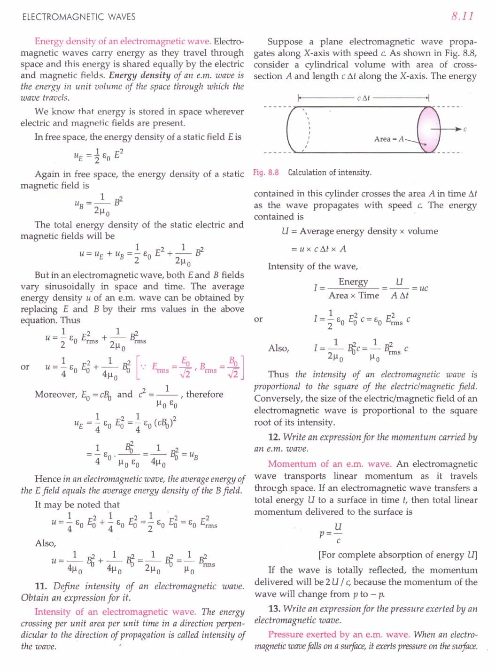
c HAP TE R
ELECTRIC CHARGES
AND FIELD
1.1 FRICTIONAL ELECTRICITY
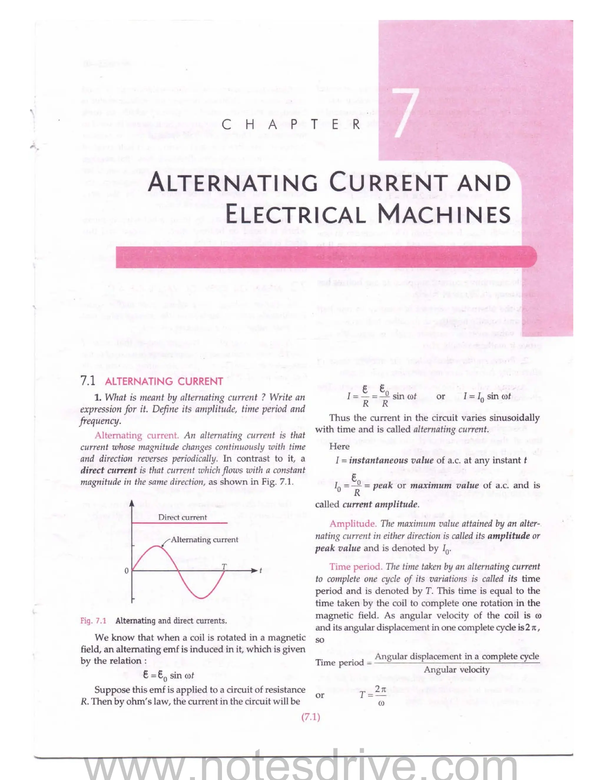
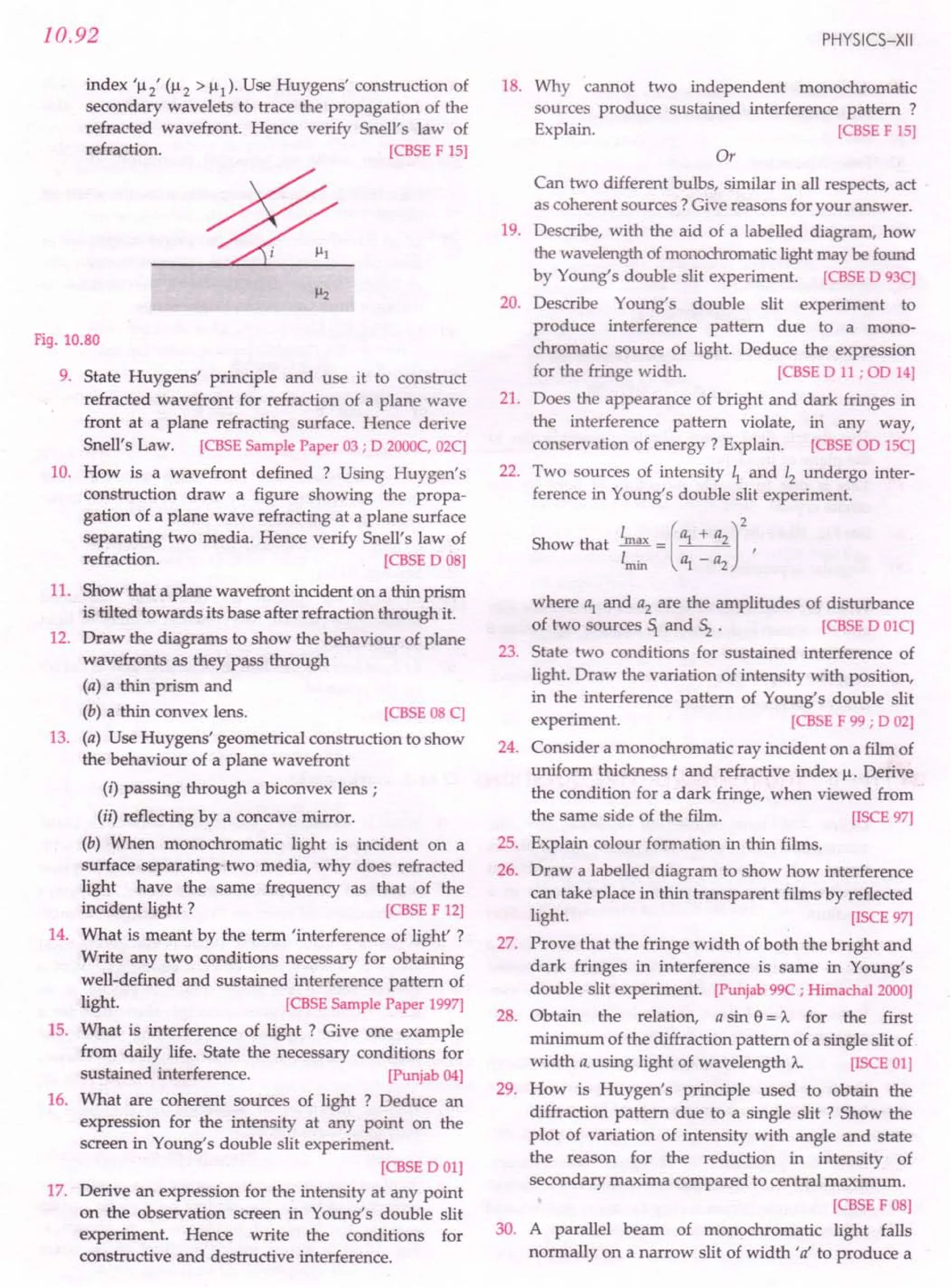
1. What is frictional electricity? When is a body said
to be electrified or charged ?
t"
Frictional electricity. If a glass rod is rubbed with a
silk cloth, or a fountain-pen with a coat-sleeve, it is able
to attract small pieces of paper, straw, lint, light feathers,
etc. Similarly, a plastic comb passed through dry hair
can attract such light objects. In all these examples, we
can say that the rubbed substance has become electrified
or electrically charged. It is because of friction that the
substances get charged on rubbing.
The property of rubbed substances due to which they
attract light objects is called electricity. The electricity
developed by rubbing orfriction is calledfrictional or static
electricitu. The rubbed substances which show this property
of attraction are said to have become electrified or
electrically charged.
2. Give a historical view offrictional electricity. From
where did the term electricity get its origin ?
Historical view of frictional electricity. In 600 B.C.,
Thales of Miletus, one of the founders of Greek science,
first noticed that if a piece of amber is rubbed with a
woollen cloth, it then acquires the property of attrac-
ting light feathers, dust, lint, pieces of leaves, etc.
In 1600 AD., William Cillbert, the personal doctor to
Queen Elizabeth - I of England, made a systematic study
of the substances that behave like amber. In his book
De Magnete (on the magnet), he introduced the name
electrica for such substances. In fact, the Greek name for
amber is elektron which is the origin of all such words:
electricity, electric force, electric charge and electron.
For Your Knowledge
~ Amber is a yellow resinous (gum like) substance
found on the shores of the Baltic sea.
~ Both electric and magnetic phenomena can be derived
from charged particles. Magnetism arises from
charges in motion. The charged particles in motion
exert both electric and magnetic forces on each other.
Hence electricity and magnetism are studied together
as electromagnetism.
1.2 ELECTRIC CHARGE
3. What is electric charge ? Is it a scalar or vector
quantity? Name its 51 unit.
Electric charge. Electric charge is an intrinsic property
of the elementary particles like electrons, protons, etc.,
of which all the objects are made up of. It is because of
these electric charges that various objects exert strong
electric forces of attraction or repulsion on each other.
Electric charge is an intrinsic property of elementary
particles of matter which gives rise to electric force between
various objects.
Electric charge is a scalar quantity. Its 51 unit is
coulomb (C). A proton has a positive charge (+ e) and an
electron has a negative charge (-e), where
e = 1.6 x 10⁻¹⁹ coulomb
(1.1)
3.
1.2
Large-scale matter thatconsists of equal number of
electrons and protons is electrically neutral. If there is
an excess of electrons, the body has a negative charge
and an excess of protons results in a positive charge.
1.3 ELECTROSTATICS
4. What is electrostatics ? Mention some of its
important applications.
Electrostatics. Electrostatics is the study of electric
charges at rest. Here we study the forces, fields and
potentials associated with static charges.
Applications of electrostatics. The attraction and
repulsion between charged bodies have many indus-
trial applications. Some of these are as follows:
1. In electrostatic loudspeaker.
2. In electrostatic spraying of paints and powder
coating.
3. In flyash collection in chimneys.
4. In a Xerox copying machine.
5. In the design of a cathode-ray tube used in
television and radar.
1.4 TWO KINDS OF ELECTRIC CHARGES
5. How will you show experimentally that (i) there are
only two kinds of electric charges and (ii) like charges
repel and unlike charges attract each other ?
Two kinds of electric charges. About 100 years ago,
Charles Du Fay of France showed that electric charges
on various objects are of only two kinds. The following
simple experiments prove this fact.
EXPERIMENT
1
(i) Rub a glass rod with silk and suspend it from a
rigid support by means of a silk thread. Bring
another similarly charged rod near it. The two
rods repel each other [Fig. l.1(a)].
Silk ~ilk
Glass + Glass
++ ) t ++ J I
'JRepulslOn 1 tic ./
~ ~_p_a_5___ Attraction
~ ~
(a) (b)
~
ilk
-_ Plastic
----JRepulsion
~ (c)
Fig. 1.1 Like charges repel and unlike charges
attract each other.
PHYSICS-XII
(ii) Bring a plastic rod rubbed with wool near the
charged glass rod. The two rods attract each
other [Fig. l.1(b)].
(iii) Now rub a plastic rod with wool and suspend it
from a rigid support. Bring another similarly
charged plastic rod near it. There will be a
repulsion between the two rods [Fig. 1.1(c)].
EXPERIMENT
2. If a glass rod, rubbed with silk, is
made to touch two small pith balls (or polystyrene
balls) which are suspended by silk threads, then the two
balls repel each other, as shown in Fig. 1.2(a). Similarly,
two pith balls touched with a plastic rod rubbed with
fur are found to repel each other [Fig. 1.2(b)]. But it is
seen that a pith ball touched with glass rod attracts
another pith ball touched with a plastic rod [Fig. 1.2(c)].
(a) Repulsion (b) Repulsion
+
- -
(c) Attraction
Fig. 1.2 Like charges repel and unlike charges attract.
From the above experiments, we note that the
charge produced on a glass rod is different from the
charge produced on a plastic rod. Also the charge
produced on a pith ball touched with a glass rod is
different from the charge produced on pith ball
touched with a plastic rod. We can conclude that:
1. There areonly two kinds of electric charges - positive
and negative.
2. Like chargesrepeland unlike chargesattract eachother.
The statement 2 is known as the fundamental law
of electrostatics.
The above experiments also demonstrate-that the
charges are transferred from the rods to the pith balls
on contact. We say that the pith balls have been
electrified or charged by contact. This property which
distinguishes the two kinds of charges is called the polarity
of charge.
4.
ELECTRIC CHARGES ANDFIELD
6. What are vitreous and resinous charges ? What
was wrong with this nomenclature?
Vitreous and resinous charges. CharlesDu Fayused the
terms vitreous and resinous for the two kinds of charges.
1. The charge developed on glass rod when rubbed with
silk was calledvitreous charge (Latin virtum =glass).
2. The charge developed on amber when rubbed with
wool was called resinous charge (amber is a resin).
But later on, these terms were found to be
misleading. For example, a ground glass rod develops
resinous electricity while a highly polished ebonite rod
develops vitreous electricity.
7. What are positive and negative charges ? What is
the nature of charge on an electron in this convention ?
Positive and negative charges. Benjamin Franklin
(1706-1790), an American pioneer of electrostatics
introduced the present-day convention by replacing
the terms vitreous and resinous by positive and
negative, respectively. According to this convention:
1. The charge developed on a glass rod when rubbed
with silk is called positive charge.
2. The charge developed on a plastic rod when rubbed
with wool is called negative charge.
The above convention is consistent with the fact
that when two opposite kinds of charges are brought in
contact, they tend to cancel each other's effect. According
to this convention, the charge on an electron is negative.
Table 1.1 gives a list of the pairs of objects which get
charged on rubbing against each other. On rubbing, an
object of column I will acquire positive charge while
that of column II will acquire negative charge.
Table 1.1 Two kinds of charges developed on rubbing
Column I Column II
(Positive charge) (Negative charge)
Glass rod Silk cloth
Flannel or cat skin Ebonite rod
Woollen cloth Amber rod
Woollen coat Plastic seat
Woollen carpet Rubber shoes
Obviously, any two charged objects belonging to
the same column will repel each other while those of
two different columns will attract each other.
For Your Knowledge
~ Benjamine's choice of positive and negative charges is
purely conventional one. However, it is unfortunate
that the charge on an electron (which is so important
to physical and chemical properties of materials)
1.3
turns out to be negative in this convention. It would
have been more convenient if electrons were assigned
positive charge. But in science, sometimes we have to
live with the historical conventions.
~ Different substances can be arranged in a series in
such a way that if any two of them are rubbed together,
then the one occurring earlier in the series acquires a
positive charge while the other occurring later acquires
a negative charge:
1. Fur 2. Flannel 3. Sealing wax
4. Glass 5. Cotton 6. Paper
7. Silk 8. Human body 9. Wood
10. Metals 11. Rubber 12. Resin
13. Amber 14. Sulphur 15. Ebonite
16. Guta parcha
Thus glass acquires a positive charge when rubbed
with silk but it acquires negative charge when rubbed
with flannel. )
1.5 ELECTRONIC THEORY OF FRICTIONAL
ELECTRICITY
8. Describe the electronic theory of frictional
electricity. Are the frictional forces electric in origin ?
Electronic theory of frictional electricity. All matter
is made of atoms. An atom consists of a small central
nucleus containing protons and neutrons, around
which revolve a number of electrons. In any piece of
matter, the positive proton charges and the negative
electron charges cancel each other and so the matter in
bulk is electrically neutral.
The electrons of the outer shell of an atom are
loosely bound to the nucleus. The energy required to
remove an electron from the surface of a material is
called its 'work function'. When two different bodies
are rubbed against each other, electrons are transferred
from the material with lower work function to the
material with higher work function. For example,
when a glass rod is rubbed with a silk cloth, some
electrons are transferred from glass rod to silk. The
glass rod develops a positive charge due to deficiency
of electrons while the silk cloth develops an equal
negative charge due to excess of electrons. The
combined total charge of the glass rod and silk cloth is
still zero, as it was before rubbing i.e., electric charge is
conserved during rubbing. ,
Electric origin of frictional forces. The only way by
which an electron can be pulled away from 'an atom is
to exert a strong electric force on it. As electrons are
actually transferred from one body to another during
rubbing, so frictional forces must have an electric origin.
5.
1.4
For Your Knowledge
~The cause of charging is the actual transfer of elec-
trons from one material to another during rubbing.
Protons are not transferred during rubbing.
~ The material with lower work function loses electrons
and becomes positively charged.
~ As an electron has a finite mass, therefore, there always
occurs some change in mass during charging. The
mass of a positively charged body slightly decreases
due to loss of some electrons. The mass of a negatively
charged body slightly increases due to gain in some)
electrons. _
1.6 CONDUCTORS AND INSULATORS
9. How do the conductors differ from the insulators?
Why cannot we electrify a metal rod by rubbing it while
holding it in our hand ? How can we charge it ?
Conductors. The substances through which electric
charges canflow easily are called conductors. They contain
a large number of free electrons which make them
good conductor of electricity. Metals, human and animal
bodies, graphite, acids, alkalies, etc. are conductors.
Insulators. The substances through which electriccharges
cannot flow easily are called insulators. In the atoms of
such substances, electrons of the outer shell are tightly
bound to the nucleus. Due to the absence of free charge
carriers, these substances offer high resistance to the
flow of electricity through them. Most of the non-
metals like glass, diamond, porcelain, plastic, nylon,
wood, mica, etc. are insulators.
An important difference between conductors and
insulators is that when some charge is transferred to a
conductor, it readily gets distributed over its entire
surface. On the other hand, if some charge is put on an
insulator, it stays at the same place. We shall discuss
this distinguishing feature in the next chapter.
A metal rod held in hand and rubbed with wool
does not develop any charge. This is because the
human body is a good conductor of electricity, so any
charge developed on the metal rod is transferred to the
earth through the human body. We can electrify the
rod by providing it a plastic or a rubber handle and
rubbing it without touching its metal part.
10. What is meant by earthing or grounding in
household circuits ? What is its importance?
Earthing and safety. When a charged body is
brought in contact with the earth (through a connecting
conductor), its entire charge passes to the ground in
the form of a momentary current. This process in which a
body shares its charges with the earth is calledgrounding or
earthing.
PHYSICS-XII
+ +
+ +
+ + <J) <J)
-;:: ~
+ +
c c c
+ + ~l
n ~l
l~
u w u W
- -
(a) (b)
Fig. 1.3 (a) Positively charge (b) Negatively charge, earthed body.
The electricity from the mains is supplied to our
houses using a three-core wiring : live, neutral and
earth wires. The live wire red in colour brings in the
current. The black neutral wire is the return wire. The
green earth wire is connected to a thick metal plate
buried deep into the earth. The metallic bodies of the
electric appliances such as electric iron, refrigerator, TV,
etc. are connected to the earth wire. When any fault
occurs or live wire touches the metallic body, the charge
flows to the earth and the person who happens to touch
the body of the appliance does not receive any shock.
1.7 ELECTROSTATIC INDUCTION
11. What is meant by electrostatic induction ?
Electrostatic induction. As shown in Fig. 1.4, hold a
conducting rod AB over an insulating stand. Bring a
positively charged glass rod near its end A. The free
electrons of the conducting rod get attracted towards
the end A while the end Bbecomes electron deficient.
The closer end A acquires a negative charge while the
remote end B acquires an equal positive charge. As
soon as the glass rod is taken away, the charges at the
ends A and Bdisappear.
Conducting rod
Excess of
electrons
Deficiency of
electrons
Insulating
stand
Fig. 1.4 Electrostatic induction.
Electrostatic induction is the phenomenon of
temporary electrification of a conductor in which opposite
charges appear at its closer end and similar charges appear at
its farther end in the presence of a nearby charged body.
The positive and negative charges produced at the
ends of the conducting rod are called induced charges and
the charge on the glass rod which induces these
charges on conducting rod is called inducing charge.
6.
ELECTRIC CHARGES ANDFIELD
12. Describe how two metal spheres can be oppositely
charged by induction.
Charging of two spheres by induction. Figure 1.S
shows the various steps involved in inducing opposite
charges on two metal spheres.
rl ~n
(a) (b)
~22 22
(c) (d)
2 2
(e)
Fig. 1.5 Two metal spheres get oppositely charged by induction.
(a) Hold the two metal spheres on insulating stands
and place them in contact, as shown in Fig. 1.S(a).
(b) Bring a positively charged glass rod near the left
sphere. The free electrons of the spheres get attracted
towards the glass rod. The left surface of the left sphere
develops an excess of negative charge while the right
side of the right sphere develops an excess of positive
charge. However, all of the electrons of the spheres do
not collect at the left face. As the negative charge
begins to build up at the left face, it starts repelling the
new incoming electrons. Soon an equilibrium is
established under the action of force of attrac- tion of
the rod and the force of repulsion due to the
accumulated electrons. The equilibrium situation is
shown in Fig. 1.S(b).
(c) Holding the glass rod near the left sphere, sepa-
rate the two spheres by a small distance, as shown in
Fig. l.S(c).The two spheres now have opposite charges.
(d) Remove the glass rod. The charges on the spheres
get redistributed. Their positive and negative charges
face each other, as shown in Fig. 1.S(d). The two
spheres attract each other.
(e) When the two spheres are separated quite apart,
the charges on them get uniformly distributed, as
shown in Fig. 1.S(e).
Thus the two metal spheres get charged by a
process called charging by induction. In contrast to the
process of charging by contact, here the glass rod does
not lose any of its charge.
1.5
13. How can you charge a metal sphere positively
without touching it ?
Charging of a sphere by induction. Fig. 1.6 shows
the various steps involved in inducing a positive
charge on a metal sphere.
(a) Hold the metal sphere on an insulating stand.
Bring a negatively charged plastic rod near it.
The free electrons of the sphere are repelled to
the farther end. The near end becomes posi-
tively charged due to deficit of electrons.
(b) When the far end of the sphere is connected to
the ground by a connecting wire, its free
electrons flow to the ground.
(c) When the sphere is disconnected from the
ground, its positive charge at the near end
remains held there due to the attractive force of
the external charge.
(d) When the plastic rod is removed, the positive
charge spreads uniformly on the sphere.
p:~ 2GPlld
(a) (b)
(e) (d)
Fig. 1.6 Charging by induction.
Similarly, the metal sphere can be negatively charged
by bringing a positively charged glass rod near it.
For Your Knowledge
~ Gold-leaf electroscope. It is a device used for detecting
an electric charge and identifying its polarity. It
consists of a vertical conducting rod passing through
a rubber stopper fitted in the mouth of a glass vessel.
Two thin gold leaves are attached to lower end of the
rod. When a charged object touches the metal knob at
the outer end of the rod, the charge flows down to the
leaves. The leaves Metal--+
diverge due to knob
repulsion of the like
charges they have
received. The degree
of divergence of the
leaves gives a
measure of the
amount of charge.
Rubber
stopper
Glass
vessel
Gold lea
Tin foil
7.
1.6
1.8 BASIC PROPERTIESOF ELECTRIC CHARGE
It is observed from experiments that electric charge
has following three basic properties :
1. Additivity 2. Quantization 3. Conservation.
We shall discuss these properties in detail in the
next few sections.
1.9 ADDITIVITY OF ELECTRIC CHARGE
14. What do you mean by additive nature of electric
charges?
Additive nature of electric charges. Like mass,
electric charge is a scalar quantity. Just as the mass of
an extended body is the sum of the masses of its
individual particles, the total charge of an extended
body is the algebraic sum (i.e., the sum taking into
account the positive and negative signs) of all the
charges located at different points inside it. Thus, the
electric charge is additive in nature.
Additivity of electric charge means that the total
charge of a system is the algebraic sum of all the individual
charges located at different points inside the system.
If a system contains charges ql' q2' ....., qn' then its
total charge is
q = ql + q2 + .....+ qn
The total charge of a system containing four
charges 2 1lC,-3 1lC,4 IlC and - 5 IlC is
q =2 IlC -3 IlC + 4 IlC - 5 IlC = -2 IlC
1.10 QUANTIZATION OF ELECTRIC CHARGE
15. What is meant by quantization of a physical
quantity?
Quantization of a physical quantity. The quanti-
zation of a physical quantity means that it cannot vary conti-
nuously to have any arbitraryvalue but it can changedisconti-
nuously to take anyone of only a discrete set of values. For
example, a building can have different floors (ground,
first, second, etc.) from the ground floor upwards but it
cannot 'have a floor of the value in-between. Thus the
energy of an electron in atom or the electric charge of a
system is quantized. The minimum amount by which a
physical quantity can change is called its quantum.
16. What is meant by quantization of electric charge ?
What is the cause of quantization of electric charge?
Quantization of electric charge. It is found
experimentally that the electric charge of any body,
large or small, is always an integral multiple of a
-certain minimum amount of charge. This basic charge
is the charge on an electron, which is denoted by e and
has magnitude 1.6 x 10⁻¹⁹ coulomb. Thus the charge on
an electron is - e, on a proton is + e and that on
a-particle is + 2e.
PHYSICS-XII
The experimental fact that electric charges occur in
discrete amounts instead of continuous amounts is called
quantization of electric charge. The quantization of electric
charge means that the total charge (q) of a body is always an
integral multiple of a basic quantum of charge (e), i.e.,
q = ne ,where n = 0, ± 1, ± 2, ± 3, .
Cause of quantization. The basic cause of quanti-
zation of electric charge is that during rubbing only an
integral number of electrons can be transferred from
one body to another.
Quantization of electric charge is an experi-
mentally verified law :
1. The experimental laws of electrolysis discov-
ered by Faraday first suggested the quanti-
zation of electric charge.
2. Millikan's oil drop experiment in 1912 on the
measurement of electric charge further estab-
lished the quantization of electric charge.
17. Can we ignore the quantization of electric
charge ? If yes, under what conditions ?
When can we ignore the quantization of electric
charge. While dealing with macroscopic charges (q = ne),
we can ignore the quantization of electric charge. This
is because the basic charge e is very small and n is very
large in most practical situations, so q behaves as if it
were continuous i.e., as if a large amount of charge
were flowing. For example, when we switch on a 60 W
bulb, nearly 2 x 10¹⁸
electrons pass through its filament
per second. Here the graininess or structure of charge
does not show up i.e., the bulb does not flicker with the
entry of each electron. Quantization of charge becomes
important at the microscopic level, where the charges
involved are of the order of a few tens or hundreds of e.
/ ,
For Your Knowledge
~ The smallest amount of charge or basic quantum of
charge is the charge on an electron or a proton. Its
exact magnitude is e = 1.602192 x 10⁻¹⁹
C
~ Quantization of electric charge cannot be explained on
the basis of classical electrodynamics or even modem
physics. However, the physical and chemical properties
of atoms, molecules and bulk matter cannot be explained
without considering the quantization of electric charge.
~ Recent discoveries in high energy physics have indi-
cated that the elementary particles like protons and
neutrons are themselves built out of more elementary
units, called quarks, which have charges (2/3) eand
(- 1/3) e Even if quark-model is established in {tIture,
the quantization of charge will still hold. Only the
quantum of charge will reduce from eto e/3.
~ Quantization is a universal law of nature. Like charge,
energy and angular momentum of an electron are also
quantized. However, quantization of mass is yet to be
established.
8.
ELECTRIC CHARGES ANDFIELD
Examples based on
uanrisation of Electric Charge
Formulae Used
1. q = ne
2. Mass transferred during charging = me x n
Units Used
q and e are in coulomb, n is pure integer.
Constants Used
e = 1.6 x 10⁻¹⁹ C, me = 9.1 x 10⁻³¹ kg
Example 1. Which is bigger - a coulomb or a charge on an
electron ? How many electronic chargesform one coulomb of
charge ? [Haryana 01]
Solution. One coulomb of charge is bigger than the
charge on an electron.
Charge on one electron, e = 1.6 x 10⁻¹⁹ C
:. Number of electronic charges in 1coulomb,
q 1 C 18
n = - = = 6.25 x 10 .
e 1.6 x 10⁻¹⁹ C
Example 2. A comb drawn through person's hair on a dry
day causes 10
22
electrons to leave the person's hair and stick
to the comb. Calculate the charge carried by the comb.
Solution. Here n = 1022, e = 1.6 x 10⁻¹⁹ C
:. q = ne=1022
x 1.6 x 10-19 =1.6 x 10³ C
As the comb has excess of electrons,
:. Charge on comb = -1.6 x 10³
C.
Example 3. If a body gives out 10
9
electrons every second,
how much time is required to get a total charge of 1 Cfrom
it? [NCERT]
Solution. Number of electrons given out by the
body in one second = 109
Charge given out by the body in one second
= ne = 109 x 1.6 x 10-19 C
= 1.6 x 10- 10 C
Time required to get a charge of 1.6 x 10⁻¹⁰
C
=ls
Time required to get a charge of 1 C
1 10 S = 6.25 x 10⁹
s
1.6 x 10-
6.25 x 10
9
------ years = 198.18 years.
365 x 24 x 3600
Thus from a body emitting 109
electrons per
second, it will take nearly 200 years to get a charge of
1 C from that body. This shows how large is one
coulomb as the unit of charge.
1.7
Example 4. How much positive and negative charge is
there in a cup of water ? [NCERT]
Solution. Suppose the mass of water contained in a
cup is 250 g. The molecular mass of water is 18 g.
Number of molecules present in 18 g of water
= Avogadro's number =6.02 x 10
23
:. Number of molecules present in a cup (or 250 g)
of water
23
n = 6.02 x 10 x 250 = 8.36 x 1024
18
Each molecule of water (HzO) contains 2 + 8 = 10
electrons as well as 10 protons.
Total number of electrons or protons present in a
cup of water,
n' = n x 10 =8.36 x 1025
Total negative charge carried by electrons or total
positive charge carried by protons in a cup of water,
q = n' e
= 8.36 x 1025 x 1.6 x 10-19 C = 1.33 x 10⁷ C
rproblems For Practice
1. Calculate the charge carried by 12.5 x 10⁸ electrons.
[CBSE D 92]
(Ans. 2 x 10- 10 C)
2. How many electrons would have to be removed
from a copper penny to leave it with a positive
charge of 10-7
C ? (Ans. 6.25 x Uy1 electrons)
3. Calculate the charge on an alpha particle. Given
charge on a proton = 1.6 x 10⁻¹⁹ C.
(Ans. + 3.2 x 10⁻¹⁹ C)
4. Calculate the charge on ~ Fe nucleus. Given char~e on
a proton = 1.6 x 10⁻¹⁹ C. (Ans. + 4.16 x 10- 8 C)
5. Determine the total charge on 75.0 kg of electrons.
(Ans. - 1.33 x uP C)
6. How many mega coulombs of positive (or
negative) charge are present in 2.0 mole of neutral
hydrogen (H2) gas?
7. Estimate the total number of electrons present in
100 g of water. How much is the total negative
charge carried by these electrons ? Avogadro's
number = 6.02 x 10²³
and molecular mass of water
= 18. (Ans. 5.35 x 10⁶ C)
HINTS
3. An alpha particle contains 2 protons and 2
neutrons.
q = + 2e.
9.
1.8
4. ~~Fe nucleuscontains 26 protons and 30 neutrons.
.. q = + 26e
5. n = Total mass 75.0 = 25 x 1031
Mass of an electron 9 x 10-31 3
q =- ne = - 25 x 1031 x 1.6 x 10-19 =-1.33 x 10¹³ e.
3
6. Number of molecules in 2.0 mole of H2 gas
= 2.0 x 6.02 x 1023
As each H2 molecule contains 2 electrons/protons, so
n = 2 x 2.0 x 6.02 x 1023 = 24.08 x 10²³
q = ne = 24.08 x 1023 x 1.6 x 10-19
= 0.3853 x 10⁶ C = 0.3853 Me.
[1 Me =106
q
7. Proceed as in Example 4.
1.11 CONSERVATION OF CHARGE
18. State the law of conservation of charge. Give some
examples to illustrate this law.
Law of conservation of charge. If some amount of
matter is isolated in a certain region of space and no
matter either enters or leaves this region by moving
across its boundary, then whatever other changes may
occur in the matter inside, its total charge will not
change with time. This is the law of conservation of
charge which states:
1. The totalchargeofan isolatedsystem remains constant.
2. The electricchargescan neither becreatednor destroyed,
they can only be transferredfrom one body to another.
The law of conservation of charge is obeyed both in
large scale and microscopic processes. In fact, charge
conservation is a global phenomenon i.e., total charge of
the entire universe remains constant.
Examples:
1. When a glass rod is rubbed with a silk cloth, it
develops a positive charge. But at the same
time, the silk cloth develops an equal negative
charge. Thus the net charge of the glass rod and
the silk cloth is zero, as it was before rubbing.
2. The rocksalt ionises in aqueous solution as
follows:
NaCl ~ Na+ + Cl"
As the total charge is zero before and after the
ionisation, so charge is conserved.
3. Charge is conserved during the fission of a 2t~U
nucleus by a neutron.
In + 235U -t I4IBa + 92Kr + 3 In + Energy
o 92 56 36 0
Total charge before fission (0 + 92)
= Total charge after fission (56 + 36 + 3 x 0)
PHYSICS-XII
4. Electric charge is conserved during the
phenomenon of pair production in which a "(-ray
photon materialises into an electron-positron pair.
y - ray ~ electron + positron
zero cha!ge (- e) ( + e)
5. In annihilation of matter, an electron and a posi-
tron on coming in contact destroy each other,
producing two y-ray photons, each of energy
0.51 MeV.
electron + positron
(-e) (+ e)
~ 2 y- rays
zero charge
For Your Knowledge
~ Conservation of charge implies that electric charges
can be created or destroyed always in the form of equal
and opposite pairs but never in isolation. For example,
in the beta decay of a neutron (zero charge), a proton
(charge + e) and an electron (charge - e) are produced.
Total charge remains zero before and after the decay.
~ The law of conservation of charge is an exact law of
nature. It is valid in all domains of nature. Even in the
domains of high energy physics, where mass changes
into energy and vice-versa, the law of conservation of
charge strictly holds good.
1.12 ELECTRIC CHARGE VS MASS
19. Compare the properties of electric charge with
those of mass of a body.
Table 1.2 Comparison of the properties of
electric charge and mass
Electric charge Mass
1. Electric charge may be Mass of a body is
positive, negative or zero. always positive.
2. Electric charge is always Quantization of mass is
quantized : q = ne not yet established.
3. Charge on a body does Mass of a body
not depend on its speed. increases with its speed.
4. Charge is strictly Mass is not conserved by
conserved. itself as some of the mass
may get changed into
energy or vice versa.
5. Electrostatic forces Gravitational forces
between two charges between two masses are
may be attractive or always attractive.
repulsive.
Electrostatic forces
,
6. Gravitational forces
between different between different bodies
charges may cancel out. never cancel out.
7. A charged body always A body possessing
possesses some mass. mass may not have any
net charge.
10.
ELECTRIC CHARGES ANDFIELD
20. How does the speed of an electrically charged
particle affect its (i) mass and (ii) charge?
Effect of speed on mass and electric charge. According
to the special theory of relativity, the mass of a body
increases with its speed in accordance with the relation:
m = 1110
g2
1-
c2
where, 1110 = rest mass of the body, c = speed of light,
and m = mass of the body when moving with speed v.
As v < c, therefore, m > 1110.
In contrast to mass, the charge on a body remains
constant and does not change as the speed of the body
changes.
1.13 COULOMB'S LAW OF ELECTRIC FORCE
21. State Coulomb's law in electrostatics. Express the
same in Sf units. Name and define the units of electric
charge.
Coulomb's law. In 1785, the French physicist
Charles Augustin Coulomb (1736-1806) experimentally
measured the electric forces between small charged
spheres by using a torsion balance. He formulated his
observations in the form of Coulomb's law which is
electrical analogue of Newton's law of Universal
Gravitation in mechanics.
Coulomb's law states that the force of attraction or
repulsion between two stationary point charges is (i) directly
proportional to the product of the magnitudes of the two
charges and (ii) inversely proportional to the square of the'
distance between them. This force acts along the line joining
the two charges.
ql q2
• •
Fig. 1.7 Coulomb's law.
If two point charges ql and q2 are separated by
distance r, then the force F of attraction or repulsion
between them is such that
1
F IX qlq2 and F IX -
r2
or
where k is a constant of proportionality, called electro-
static force constant. The value of k depends on the
nature of the medium between the two charges and the
system of units chosen to measure F, ql' q2 and r.
.For the two charges located in free space and in 51
units, we have
k = _1_ =9 x 10⁹ Nm2 C-2
411: EO
1.9
where EO is called permittivity of free space. So we can
express Coulomb's law in 51 units as
F = _1_ qlq2
411: EO' r2
Units of charge. (i) The Sf unit of charge is coulomb. In
the above equaticn.if ql = q~ = 1C and r = 1m, then
1 .
F = -- =9 x 10⁹ N
. 4rc EO
SO one coulomb is that amount of charge that repels an
equal and similar charge with a force of 9 x 10⁹
N when
placed in vacuum at a distance of one metre from it.
(ii) In electrostatic cgs system, the unit of charge is
known as electrostatic unit of charge (e.s.u. of charge) or
statcoulomb (stat C).
One e.s.u. of charge or one statcoulomb is that charge
which repels an identical charge in vacuum at a distance of
one centimetre from it with aforce of 1dyne.
1 coulomb = 3 x 10⁹
stat coulomb
= 3 x 10⁹
e.s. u. of charge
(iii) In electromagnetic cgs system, the unit of
charge is abcoulomb or electromagnetic unit of
charge (e.m.u. of charge).
1 coulomb = 1~abcoulomb = 1~e.m.u. of charge
For Your Knowledge
> A torsion balance is a sensitive device to measure force.
> When the linearsizesof chargedbodies aremuch smaller
than the distancebetweenthem,theirsizesmaybe ignored
and the charged bodies are called point charges.
> Coulomb's law is valid only for point charges.
> In 51units, the exact value of the combination 411: EO is
4 10
7
C2N-1 -2
11:EO =? m
where c is the speed of light in vacuum having the exact
value 299792458 x 108
ms-I
.
•> Electrostatic force constant,
k= 8.98755 xl 09
Nm2
C2
c: 9 x 10⁹
Nm2
C2
.
> Permittivity offree space,
EO =8.8551485 x10⁻²
C2
N-1
m-2
.:::9xlO-2C2N-I m-2.
> 51 unit of permittivity
= coulomb x coulomb =C2N-Im-2
newton x metre2
The unit C2
N-1
m-2
is usually expressed as farad per
metre (Fm-I
) .
> More strictly,the 51unit of charge 1 coulomb is equal to
1ampere-second, where 1 ampere is defined in terms of
the magnetic forcebetween two current carrying wires.
11.
1.10
1.14 COULOMB'S LAWIN VECTOR FORM
22. Write Coulomb's law in vector form. What is the
importance of expressing it in vector form ?
Coulomb's law in vector form. As shown in Fig. 1.8,
consider two positive point charges q1 and q2 placed in
vacuum at distance r from each other. They repel each
other.
~ ~
F12
•••••
I----· --------
-------"·---,l·~F21
+ ql + q2
Fig. 1.8 Repulsive coulombian forces for q 1q2 > o.
In vector form, Coulomb's law may be expressed as
-4
F21 = Force on charge q2 due to q1
1 qlq2 "
=-- --r.
4n I: . ? 12
o
-4
" r.
where r12 = R , is a unit vector in the direction from ql
r
to q2.
-4
Similarly, F12 = Force on charge q1 due to q2
1 qlq2 "
=--·-2- r21
4n 1:0 r
-4
" r,
where r21 = -.11, is a unit vector in the direction from q2
r
to q1.
The coulombian forces between unlike charges
(qlq2 <0) are attractive, as shown in Fig. 1.9.
Fig. 1.9 Attractive coulombian forces for q 1q2 < o.
Importance of vector form. The vector form of cou-
lomb's law gives the following additional information:
1 1 -+-+
1. As r21 = - r12, therefore F21 = - F12·
This means that the two charges exert equal and
opposite forces on each other. So Coulombian
forces obey Newton's third law of motion.
-4 -4
2. As the Coulombian forces act along F12 or F21,
i.e., along the line joining the centres of two
charges, so they are central forces.
23. What is the range over which Coulombian forces
can act ? State the limitations of Coulomb's law in
electrostatics.
PHYSICS-XII
Range of coulombian forces. Coulombian forces act
over an enormous range of separations (r), from
nuclear dimensions (r = 10-15
m) to macroscopic dis-
tances as large as 1018
m. Inverse square is valid over
this range of separation to a high degree of accuracy.
Limitations of Coulomb's law. Coulomb's law is
not applicable in all situations. It is valid only under
the following conditions:
1. The electric charges must be at rest.
2. The electric charges must be point charges i.e.,
the extension of charges must be much smaller
than the separation between the charges.
3. The separation between the charges must be
greater than the nuclear size (la-15
m), because
for distances <la-15m, the strong nuclear force
dominates over the electrostatic force.
1.15 DIELECTRIC CONSTANT:
RELATIVE PERMITIIVITY
24. What do you mean by permittivity of a medium?
Define dielectric constant in terms offorces between two
charges.
Permittivity : An introduction. When two charges
are placed in any medium other than air, the force
between them is greatly affected. Permittivity is a
property of the medium which determines the electricforce
between two chargessituated in that medium. For example,
the force between two charges located some distance
apart in water is about I/80th of the force between
them when they are separated by same distance in air.
This is because the absolute permittivity of water is
about 80 times greater than the absolute permittivity of
air or free space. .
Dielectric constant or relative permittivity. Accor-
ding to Coulomb's law; the force between two point
charges ql and q2' placed in vacuum at distance r from
each other, is given by
F = _1_. ql~2 ... (1)
vac 4n I: r:
o
When the same two charges are placed same
distance apart in any medium other than vacuum, the
force between them becomes
F d = _1_. ql~2 ... (2)
me 4nl: r:
The quantity I: is called absolute permittivity or just
permittivity of the intervening medium. Dividing
equation (1) by equation (2), we get
1 qlq2
Fvac = ~·7 I:
Fmed _1_ ql q2 1:0
4nl:· r2
12.
ELECTRIC CHARGES ANDFIELD
The ratio(E / EO) of thepermittivity (E) of the medium to the
permittivity (EO) of free space is called relative permittivity
(Er) or dielectric constant (K) of the given medium. Thus
E F
e, or K=-=~
EO Frned
So one can define dielectric constant in terms of
forces between charges as follows :
The dielectric constant or relative permittivity of a
medium may be defined as the ratio of theforce between two
charges placed some distance apart in free space to theforce
between the same two charges when they are placed the same
distance apart in the given medium.
Clearly, when a material medium of dielectric
constant K is placed between the charges, the force
between them becomes 1/ K times the original force in
vacuum. That is,
F = Fvac
rned K
Hence the Coulomb's law for any material medium
may be written as
K (vacuum) = 1
K (air) = 1.00054
K (water) = 80.
Formulae Used
1. t: = _1_. ql 2q2
vac 41t E r
o
2 t. __ 1_ qlq2
• rned - 41t E K r2
o
Units Used
%, q2 are in coulomb, F in newton and r in metre.
Constant Used
k = _1_ = 9 x 10⁹ Nm2c:-2
41t EO
Example 5. The electrostatic force of repulsion between two
positively charged ions carrying equal charges is~.7 x 10-9
N,
when they are separated by a distance of 5 A How many
electrons are missing from each ion ?
Solution. Here F =3.7 x 10⁻⁹ N,
r = 5 A = 5 x 10⁻¹⁰
m, ql = q2 = q (say)
As F =_1_. q1q2
41tEo ?
1.11
or
_99x109xqxq
3.7 x 10 = 10 2
(5 x 10- )
2 = 3.7 x 10-
9
x 25 x 10-
20
= 10.28 x 10-38
q 9 x 10⁹
q = 3.2 x 10⁻¹⁹ C
Number of electrons missing from each ion is
q 3.2 x 10⁻¹⁹
n=-= =2.
e 1.6 x 10⁻¹⁹
or
Example 6. A free pith-ball A of 8 g carries a positive
charge of 5 x 10⁻⁸ C. What must be the nature and
magnitude of charge that should be given to a second
pith-ball Bfixed 5 cm below theformer ball so that the upper
ball is stationary? [Haryana 01]
Solution. The pith-ball Bmust be of positive charge
i.e., of same nature as that of A, so that the upward
force of repulsion balances the weight of pith-ball A
When the pith-ball A remains F
stationary, ?
F=~g T A q)
or _1_ q1q2= mg
41tEo? - -1 5 em m)g
But ~=8g=8xlO-3kg 1 0
B q2
q1 = 5 x 10⁻⁸
C
r = 5 em =0.05 m Fig. 1.10
9 x 109
x 5 x 10-8 x q2 -3
------;;-2--= =8x 10 x 9.8
(0.05)
8 x 9.8 x {0.05l x 10- 4
q2 = 9 x 5
or
= 4.36 x 10⁻⁷ C (positive).
Example 7. A particle of mass m and carrying charge - q1
is moving around a charge + q2 along a circular path of
radius r. Prove that the period of revolution of the charge - q1
about + q2 is given by
r--=----:-
161t3 E mr3
T= 0
q1q2
Solution. Suppose charge - q1 moves around the
charge + q2 with speed v along the circular path of
radius r. Then
Force of attraction between the two charges
= Centripetal force
1 q1q2_ mv2
or 41tEo 7 --r- or
_1_ q1q2
41tEo mr
v=
13.
1.12
The period ofrevolution of charge - ql around + q2
will be
Example 8. Two particles, each having a mass of 5 g and
charge 1.0 x 10⁻⁷
C , stay in limiting equilibrium on a
horizontal table with a separation of 10 em between them.
The coefficient offriction between each particle and the table
is the same. Find !.L
Solution. Here ql = q2 = 1.0 x 10⁻⁷
C,
r=10 em =0.10 m, m=5 g=5 x 10⁻³
kg
The mutual electrostatic force between the two
particles is
q q 9 x 109 x (1.0 x 10-7)2
F = k ~ 2 = 0.009 N
r (0.10)
The limiting force of friction between a particle and
the table is
f =!l x mg =!l x 5 x 10-3
x 9.8 =0.049 !l N
As the two forces balance each other, therefore
0.049 !l = 0.009
= 0.009 = O.lB.
!l 0.049
or
Example 9. (a) Two insulated charged copper spheres A
and B have their centres separated by a distance of 50 cm.
What is the mutual force 1,electrostatic repulsion if the
charge on each is 6.5 x 10- C? The radii of A and Bare
negligible compared to the distance of separation. Also
compare this force with their mutual gravitational attraction
if each weighs 0.5 kg.
(b) What is the force of repulsion if (i) each sphere is
charged double the above amount, and the distance between
them is halved; (ii) the two spheres are placed in water ?
(Dielectric constant of water = 80). [NCERT]
Solution. (a) Here ql = q2 =6.5 x 10⁻⁷
C,
r = 50 em. =0.50 m
Using Coulomb's law,
F. = k. qlq2
air r2
= 9 x 10⁹. 6.5 x 10-
7
x 6.5 x 10-
7
N
(0.50)2
= 1.5 x 10⁻²
N.
The mutual gravitational attraction,
F =G~""2
e R2
6.67 x 10-
11
x 0.5 x 0.5 = 6.67 x 10⁻¹¹ N
(0.5)2
Clearly, Fe « ~ir .
PHYSICS-XII
(b) (i) When charge on each sphere is doubled, and
the distance between them is halved, the force of
repulsion becomes
F'. =k.2ql·2q2 =16k.q1q2
arr (r / 2)2 r2
= 16 x 1.5 x 10-2 = 0.24 N.
(ii) The force between two charges placed in a
medium of dielectric constant K is given by
F =_1_ ! qlq2
4m,o· K· r2
For water, K = 80
F = ~ir = 1.5 x 10- 2
water K 80
. =1.875 x 10⁻⁴
N=-1.9 x 10⁻⁴
N.
Example 10. Suppose thespheresA and B in Example 9 have
identical sizes. A third sphere of the same size but uncharged
is brought in contact with thefirst, then brought in contact
with the second, and finally removed from both. What is the
new force of repulsion between A and B ? [NCERT]
Solution. Charge on each of the spheres A and B is
q=6.5xlO~7C
When a similar but uncharged sphere C is placed in
contact with sphere A, each sphere shares a charge
q/ 2, equally.
q Charge = 0 q/2 q/2
o + @ ---. GX9
q q12 3q/43q/4
0+@---'~
«n 3q/4
AO--'---OB
Fig. 1.11
Now when the sphere C (with charge q/ 2) is placed
in contact with sphere B (with charge q), the charge is
redistributed equally, so that
Charge on sphere B or C =! (q + 1)= 3q
2 2 4
•. New force of repulsion between A and B is
3q q
F=_l_ 4·2"
41tEo· ,2
= ~ x 1.5 x 10⁻²
N = 0.5625 x 10⁻²
N
8
=- 5.7 x 10⁻³
N.
Example 11. Two similarly equally charged identical metal
spheres A and B repel each other with aforce of 2.0 x 10⁻⁵ N.
A third identical uncharged sphere C is touched to A, then
placed at the midpoint between A and B. Calculate the net
electrostatic force on C. [CBSE 00 03]
14.
ELECTRIC CHARGES ANDFIELD
Solution. Let the charge on each of the spheres A
and B be q. If the separation between A and B is r, then
electrostatic force between spheres A and B will be
2
F = k . q2 =2.0 x 10⁻⁵ N
r
When sphere C is touched to A, the spheres share
charge q 12 each, because both are identical.
Force on C due to A
(qI2)2 q2
=k --=k- alongAC
. (r 12)2 ,2 ,
Force on C due to B
-k q.ql2 -k 2q2 I BC
- . (rI2)2 - '7' aong
Since these forces act in opposite directions,
therefore net force on C is
, 2 q2 q2 q2 -5
F = k . -2 - k . 2" = k 2" = 2.0 x 10 N, along Be.
r r r
Example 12. Two identical charges, Q each, are kept at a
distance rfrom each other. A third charge q is placed on the
line joining the above two charges such that all the three
charges are in equilibrium. What is the magnitude, sign and
position of the charge q ? [CBSE OD 94, 98]
Solution. Suppose the three charges be placed in
the manner, as shown in Fig. 1.12.
14 r ~I
14 x ~I B
AI I Ie
Q q Q
Fig. 1.12
The charge q will be in equilibrium if the forces
exerted on it by the charges at A and C are equal and
opposite.
k Qq=k ~
. x2 . (r-x)2
or
or x=r-x
r
x=-
2
or
Since the charge at A is repelled by the similar
charge at C, so it will be in equilibrium if it is attracted
by the charge q at B, i.e., the sign of charge q should be
opposite to that of charge Q.
Force of repulsion between charges at A and C
= Force of attraction between charges
at A and B
k ~=k Q.Q or q= Q.
(r 12)2,2 4
or
Example 13. Two point charges + 4e and + e are 'fixed' a
distance 'a' apart. Where should a third point charge q be
placed on the line joining the two charges so that it may be in
1.13
equilibrium ? In which case the equilibrium will be stable
and in which unstable ?
Solution. Suppose the three charges are placed as
shown in Fig. 1.13. Let the charge q be positive.
+4e +q +e
I
• I ~ I
F2 F1
I, x ,I, a-x--l
Fig. 1.13
For the equilibrium of charge + q, we must have
Force of repulsion Fl between + 4e and + q
= Force of repulsion F2between + e and + q
1 4e x q 1 ex q
4Tc!:O ~ = 4m:o (a - X)2
4 (a - x)2 = x2
2 (a - x) = ± x
2a
x =- or 2a
3
As the charge q is placed between + 4e and + e, so
only x = 2 a 13 is possible. Hence for equilibrium, the
charge q must be placed at a distance 2al3 from the
charge + 4e.
We have considered the charge q to be positive. If
we displace it slightly towards charge e, from the
equilibrium position, then Fl will decrease and F2will
increase and a net force (F2 - F1
) will act on q towards
left i.e., towards the equilibrium position. Hence the
equilibrium of positive q is stable.
Now if we take charge q to be negative, the forces Fl
and F2will be attractive, as shown in Fig. 1.14.
or
or
or
+ 4e -q +e
I
• I ~ I
F1 F2
I, x ,I a-x--l
Fig. 1.14
The charge - q will still be in equilibrium at
x = 2 a 13. However, if we displace charge - q slightly
towards right, then Fl will decrease and F2 will
increase. A net force (F2 - F1
) will act on - q towards
right i.e., away from the equilibrium position. So the
equilibrium of the negative q will be unstable.
Example 14. Two 'free' point charges + 4e and + e are
placed a distance 'a' apart. Where should a third point charge
q be placed between them such that the entire system may be
in equilibrium? What should be the magnitude and sign of q ?
What type of a equilibrium will it be ?
15.
1.14
Solution. Suppose thecharges are placed as shown
in Fig. 1.15.
+4e -q +e
. ~ .
III
• ~ III
F F' F1
I, x
I,
F2
---ojo·I·>--a - x------l
a .1
Fig. 1.15
As the charge + e exerts repulsion F on charge + 4e,
so for the equilibrium of charge +4e, the charge - q
must exert attraction F' on +4e. This requires the
charge q to be negative.
For equilibrium of charge + 4e,
F = F'
1 4e x e 1 4e x q
411:Eo ----;;r = 411:Eo ~
ex2
q=-
a2
For equilibrium of charge - q,
Attraction F1between + 4e and - q
= Attraction F2between + e and - q
1 4e x q 1 ex q
.. 411:Eo ~ = 411:Eo (a - x)2
x2 =4(a _x)2
x =2a/3
ex2 e 4a2 4e
q=-=- -=-
a2 a2' 9 9'
The equilibrium of the negative charge q will be
unstable.
or
or
Hence
Example 15. Two point charges of charge values Q and q
are placed at distances x and x /2 respectively from a third
charge of charge value 4q, all charges being in the same
straight line. Calculate the magnitude and nature of charge
Q, such that the netforce experienced by the charge q is zero.
[CBSE D 98].
Solution. Suppose the three charges are placed as
shown in Fig. 1.16.
~ q Q
• III· ~ •
A F8 C FA B
Fig. 1.16
For the equilibrium of charge q, the charge Q must
have the same sign as that of q or 4q , so that the forces
FA and FBare equal and opposite.
As FA = FB
1 4qx q 1 qx Q
411:Eo' (x/2)2 = 411:Eo' (x/2)2
Q=4q.
or
PHYSICS-XII
Example 16. A charge Q is to be divided on two objects.
What should be the values of the charges on the two objects
so that the force between the objects can be maximum ?
Solution. Let q and Q - q be the charges on the two
objects. Then force between the two objects is
F=_I_ q(Q-q)
411:EO . ,2
where r is the distance between the two objects.
For F to be maximum,
dF =0
dq
1 .~.~(qQ_q2)=0
411:EO ,2 dq
~ (qQ _ q2) = 0
dq
Q -2q =0
q= Q
2
or
or
or
or
i.e., the charge should be divided equally on the two
objects.
Example 17. Two identical spheres, having charges of
opposite sign attract each other with aforce of 0.108 Nwhen
separated by 0.5 m. The spheres are connected by a conduc-
ting wire, which then removed, and thereafter they repel each
other with aforce of 0.036 N. What were the initial charges
on the spheres ?
Solution. Let + q1and - q2be the initial charges on
the two spheres.
(a) When the two spheres attract each other,
F = k q1~2 i.e., 0.108 =9 x 10⁹. q1q22
r: (0.5)
= 0.108 x (0.5)2 =3 x 10 -12
q1q2 9 x 10⁹
(b) When the two spheres are connected by the
wire, they share the charges equally.
q + (- q) q - q
:. Charge on each sphere = 1 2 = _1
__ 2
2 2
i.e.,
Force of repulsion between them is
F= k(¥)(¥)
,2
0.036 = 9 x 10
9
. (q1 - q2)2
(0.5)2 2
( _ )2 = 0.036 x (0.5)2 x 4 = 4 x 10-12
.. q1 q2 9 x 10⁹
q1 -q2 =2 x 10⁻⁶
...(i)
or
16.
ELECTRIC CHARGES ANDFIELD
Now (q1 + q2)2 = (q1 - q2)2 + 4q1q2
= (2 x 10⁻⁶)2 + 4 x 3 x 10-12
= 16 x 10-12
q1+ q2 = 4 x 10⁻⁶
... (ii)
On solving equations (i) and (ii), we get
q1 = 3 x 10⁻⁶
C and q2 = 10-6
C
which are the initial charges on the two spheres.
Example 18. Two small spheres each having mass m kg
and charge q coulomb are suspended from a point by
insulating threads each Imetre long but of negligible mass. If
a is the angle, each thread makes with the vertical when
equilibrium has been attained, show that
q2 = (4 mgl2 sin2
a tan a) 4n EO [Punjab 95]
Solution. The given situation is shown in Fig. 1.17.
Each of the spheres A and B is acted upon by the
following forces:
(i) its weight mg, (ii) tension T in the string
(iii) the force of repulsion F given by
1 q2
F = -- . -----:::i ... (i)
4n EO Alj-
o
~~'
,
,
F~i--------c ---------
"
mg
Fig. 1.17
As the forces are in equilibrium, the three forces on
sphere A can be represented by the three sides of
t!. AOC taken in the same order. Hence
~= mg =~
AC OC AO
AC
or F = mg x - ... (ii)
OC
From (i) and (ii), we have
1 q2 AC
--.--=mgx-
4nEo AW OC
But AC = I sin a, OC = I cas a, AB =2 AC =21 sin a
1 q2 I sin a
--. =mgx--
4n EO 412 sin2
a I cos a
or q2 = (4 mg 12 sin2
a tan a) 4n EO'
1.15
~rOblems For Practice
1. Obtain the dimensional formula of EO'
(Ans. M-1
L-3
T4
A2)
2. Calculate coulomb force between two a-particles
separated by a distance of 3.2 x 10⁻¹⁵ m in air.
[CBSE 00 92]
(Ans. 90 N)
3. Calculate the distance between two protons such
that the electrical repulsive force between them is
equal to the weight of either. [CBSE 0 94]
(Ans. 1.18 cm)
4. How far apart should the two electrons be, if the
force each exerts on the other is equal to the weight
of the electron ? Given that e = 1.6 x 10⁻¹⁹
C and
me = 9.1 x 10⁻³¹ kg. [Haryana 02]
(Ans. 5.08 m)
5. A pith-ball A of mass 9 x 10⁻⁵ kg carries a charge of
5fie. What must be the magnitude and sign of the
charge on a pith-ball B held 2 em directly above the
pith-ball A, such that the pith-ball A remains
stationary ?
(Ans. 7.84 pC, sign opposite to that of A)
6. Two identical metal spheres having equal and
similar charges repel each other with a force of
103 N when they are placed 10 em apart in a medium
of dielectric constant 5. Determine the charge on
each sphere. (Ans. 23.9 x 10⁻⁶ C)
7. The distance between the electron and proton in
hydrogen atom is 5.3 x 10⁻¹¹
m. Determine the magni-
tude of the ratio of electrostatic and gravitational
force between them.
Given me = 9.1 x 10⁻³¹
kg, mp = 1.67 x 10⁻²⁷ kg,
e = 1.6 x 10⁻¹⁹
C and G = 6.67 x 10⁻¹¹
Nm 2 kg-2.
(Ans. Fe / Fc = 2.27 x 1039
)
8. Two identical metallic spheres, having unequal,
opposite charges are placed at a distance 0.90 m
apart in air. After bringing them in contact with
each other, they are again placed at the same
distance apart. Now the force of repulsion between
them is 0.025 N. Calculate the final charge on each
of them. [CBSE D 02C]
(Ans. 1.5 x 1O-6q
9. A small brass sphere having a positive charge of
1.7 x 10⁻⁸ C is made to touch another sphere of the
same radius having a t;legativecharge of 3.0 x 10⁻⁹
e.
Find the force between them when they are
separated by a distance of 20 cm. What will be the
force between them when they are immersed in an
oil of dielectric constant 3 ?
(Ans. 1.1 x 10⁻⁵ N; 0.367 x 10⁻⁵ N)
17.
1.16
10. The sumof two point charges is 71lC. They repel
each other with a force of 1 N when kept 30 ern
apart in free space. Calculate the value of each
charge. [CBSE F 091
(Ans. 51lC, 21lC)
11. Two point charges q1 = 5 x 1O-6
C and q2 = 3 x 1O-6
C
are located at positions (1 m, 3 rn, 2 m) and (3 rn,
~ ~
5 m, 1 m) respectively. Find the forces li2 and F21
using vector form of Coulomb's law.
---t 3 1 / 1
[AnS.li2 = -5xl0- (2i + 2j -k)N,
---t 3 1 / 1
F21 = svro: (2i + 2j -k)N]
12. Three equally charged small objects are placed as
shown in Fig. 1.18. The object A exerts an electric
force on object B equal to 3.0 x 1O-6
N.
A B C
• • • 3.
14 2cm ~14 1em ----+I
Fig. 1.18
(i) What electric force does C exert on B?
(ii) What is the net electric force on B?
[Ans. (i) 12.0 x 10⁻⁶
N, along BA
(ii) 9.0 x 10⁻⁶
N, along BAl
13. Two identical metallic spheres A and B,each carry-
ing a charge q, repel each other with a force F. A
third metallic sphere C of the same size, but un-
charged, is successively made to touch the spheres
A and B,and then removed away. What is the force
of repulsion between A and B? (Ans. 3F /8)
14. Two point charges + ge and +e are kept at a distance
a from each-other. Where should we place a third
charge q on the line joining the two charges so that
it may be in equilibrium ?
(Ans. 3: from + ge Charge)
15. Two point electric charges of values q and 2q are
kept at a distance d apart from each other in air. A
third charge Q is to be kept along the same line in
such a way that the net force acting on q and 2q is
zero. Calculate the position of charge Qin terms of q
and d. [CBSE D 98]
(Ans. At a distance of (..fi - 1) d from charge q)
16. A charge q is placed at the centre of the line joining
two equal charges Q. Show that the system of three
charges will be in equilibrium if q = -Q/ 4.
[CBSE OD 05]
17. Two pith-balls each weighing 10-3kg are
suspended from the same point by means of silk
PHYSICS-XII
threads 0.5 m long. On charging the balls equally,
they are found to repel each other to a distance of
0.2 m. Calculate the charge on each ball.
[Haryana 2002]
(Ans. 2.357 x 10- 6 C)
HINTS
1. F = _1_ . q1 :}2 or EO
= lit q2
2
41tEo r 41tFr
[E 1= AT. AT = [~lL-3T4 A2l.
o MLT2. L2
2. Here q1 = q2 = 2e = 3.2 x 10⁻¹⁹C, r = 3.2 x 10⁻¹⁵ m
F= _1_ lItq2
41tEo' r2
9 x 109 x 3.2 x 10-19 x 3.2 x 10-19
----------~,_------90N
(3.2 x 10 15)2 -.
For a proton, m = 1.67 x 10⁻²⁷ kg,
q = + e = 1.6 x 10⁻¹⁹C.
Weight of proton = Electrical repulsive force
q x q
mg = k.--2
-
r
9 x 109
x(1.6 x 10-19)2
1.67 x 10 27 x 9.8
or
r2 = kq2
mg
= 23.04 x 10-2 = 0.014
16.36
or r = 0.0118 m = 1.18 em.
exe
4. me g = k . --2-
r
or
9 x 109 x(1.6 x 10-19)2
_____ '---,,.- __ --C- = 25.84
9.1 x 10 31x 9.8
r= 5.08 m.
5. The pith-ball B must have charge opposite to that of
A so that the upward force of attraction balances
the weight of pith-ball A.
When the pith-ball A remains
stationary, T
Q20B
2r~A
Q)
m)g
or
F = rr;g
_1_ q1 q2 = rr; g
41tEO r2
rr; = 9 x 10⁻⁵ kg,
q1 = 51lC = 5 x 10⁻⁶ C,
r= 2cm =0.02 m
9x109x5xlO-6xq2 -5
--------"2,-----'= = 9 x lOx 9.8
(0.02)
q2 = 7.84 x 10⁻¹²C = 7.84 pc.
But
Fig. 1.19
or
18.
ELECTRIC CHARGES ANDFIELD
9 x 10⁹
x q2
103=---;,-
5 x (0.10)2
6. F=_l_ q1i2
41tEOK' ..
or q = 23.9 x 10⁻⁶
C.
7. Proceed as in illustrative problem on page 1.18.
8. The two spheres will share the final charge equally.
Let q be the charge on each sphere.
F= _1_. qlq2 = 0.025 N
.. 41t Eo r2
9 x 10⁹ x q x q
-----<-2 ----'-= 0.025
(0.90)
q2 = oms x (0~90)2= 225 x 10-14
9 x 10
q = 1.5 x10⁻⁶ C.
or
or
or
9. Charge shared by each sphere
= (17 - 3) x 10-
9
= 7 x 10⁻⁹ C
2
9 x 109 x(7 x 10-9)2 -5
F. = 2 =1.lx10 N
au (0.20)
9 x 109 x(7 x10-9)2 -5
E.] = 2 = 0.367 x10 N.
01 3 x (0.20)
10. Here F = 1N, r = 30 m
F=k~2
9 x 109
x 1M2
1= ------,,'-'-'-"-
(0.30)2
10-11
or q1q2=
But q1+ q2 = 7!-1C= 7x10⁻⁶ C
Now (q1 - q2)2 = (q1 + q2)2 - 4q1q2
= 49 x 10-12- 4 x 10-11
= 9 x 10-12
or q1 - q2 = 3 x 10-6 = 3!-1C
On solving (i) and (ii), we get
q1 = 5!-1C and q2 = 2!-1C.
As
-+ 1 1 1 ~ 1 1 "
11. Here 1 =(i +3j+2k )m, '2 =(3i +5j+k)m
--» -+ -+ 1 1 1 1 1 1
12 = '2-1 =(3i +5j+k )-(i +3j +2k)
-+ ~2 2 2
112 I = 2 + 2 + (-1) = 3 m
1.17
-+ 1 ~q2"
F21= -- -2- 12
41tEo 12
9x109x5x10-6x3x10-6 (2i+2J-k)
3
2
3
3 " 1 1
= 5x10- (2i +2j -k)N
-+ -+ -3 ~ <' 1
Also, li2=-Fz1=-5xlO (21+2J-k)N.
12. Here AB = 2 em = 0.02 m, Be = 1em = 0.01 m
q q q
. ... ~ .
A FBe B FBA C
I· 2 ern ·1· 1 em----l
Fig. 1.20
Let q be the charge on each object.
F __ 1_~
BA - 41tEo(AB)2
-6 9 x 10⁹ x q2
or 3.0x10 = 2
(0.02)
2 4 10-19C
or q = - x .
3
(i)
1 q x q 9 4 x 10-19
F =-----=9xlO X---"
BC 41t1,o
.(BC)2 3 x(0.01)2
= 12.0 x 10⁻⁶
N, along BA.
...(i)
(ii) Net force on charge at B,
F = FBC - FBA = (12.0 - 3.0) x 10-6
= 9.0 x10⁻⁶ N, along BA.
13. Proceed as in Example 10 on page 1.12.
14. Force between + ge and q = Force between +e and q
k gexq=k ~
.. . x2 . (a - x)2
3 1
or or x = 3a /4.
x a-x
...(ii) 15. For equilibrium of charges q and 2q, the charge Q
must have sign opposite to that of q or 2q. Suppose
it is placed at distance x from charge q.
q Q 2q
• • •
I--- x ---+1·1__
· - d - x-----1
Fig. 1.21
For equilibrium of charge q,
k qQ - k q x2q
x2 - d2
For equilibrium of charge 2q,
kqx2q=k Qx2q
d2 (d-x)2
...(i)
...(ii)
19.
1.18
From (i) and(ii), we get,
k qQ =k Q x2q
x2 (d - x)2
or 2x2 = (d - x)2
or ..fix = d-x
or x = ~ 1
d = (..fi - 1)d
,,2 + 1
i.e., the charge Q must be placed at a distance of
(..fi - 1) d from the charge q.
16. Suppose the three charges are placed as shown in
Fig. 1.22.
Q q Q
• • •
A C B
14 x .14 x .1
Fig. 1.22
Clearly, the net force on charge q is zero. So it is in
equilibrium, the net force on other two charges
should also be zero.
Total force on charge Q at point B is
_1_ QQ + _1_ q Q = 0
41t Eo . (2x)2 41t EO x2
1 qQ 1 QQ
41t EO ?" = - 41t EO . (2x)2
q=-Q/4.
17. In /!,. DCA of forces, we have
F mg T
-=-=-
AC DC DA
or
or
F
.•..
-O
A
q
mg
Fig. 1.23
AC
F=mgx-
DC
1 q2 AC
--.--=mgx-
41tEo AB2 DC
9 x 10⁹
x q2 10- 3 x 9.8 x 0.1
(0.2)2 ~(0.5)2 _ (0.1)2
q = 2.357 xlO-6 C
PHYSICS-XII
1.16 COMPARING ELECTROSTATIC AND
GRAVITATIONAL FORCES
25. Give a comparison of the electrostatic and gravi-
tational forces.
Electrostatic force vs gravitational force. Electro-
static force is theforce of attraction or repulsion between two
charges at rest while the gravitational force is the force of
attraction between two bodies by virtue of their masses.
Similarities:
1. Both forces obey inverse square law i.e.,
1
FCX:,z'
2. Both forces are proportional to product of
masses or charges.
3. Both are central forces i.e., they act along the line
joining the centres of the two bodies.
4. Both are conservative forces i.e., the work done
against these forces does not depend upon the
path followed.
5. Both forces can operate in vacuum.
Dissimilarities:
1. Gravitational force is attractive while electro-
static force may be attractive or repulsive.
2. Gravitational force does not depend on the nature
of the medium while electrostatic force depends on
the nature of the medium between the two charges.
3. Electrostatic forces are much stronger than
gravitational forces.
Illustrative Problem. Coulomb's lawfor electricalforce
between two charges and Newton's lawfor gravitational force
between two masses, both have inverse-square dependence on
the distance between charges/masses.
(a) Compare the strength of theseforces by determining
the ratio of their magnitude (i)for an electron and a
proton and (ii)for two protons.
(b) Estimate the accelerations for electron and proton
due to the electric~lforce attheir mutual attraction
when they are 1 A (= 10-1
m) apart.
How much is the electrostatic force stronger than
the gravitational force?
(a) (i) From Coulomb's law, the electrostatic force
between an electron and a proton separated by
distance r is
Negative sign indicates that the force is attractive.
From Newton's law of gravitation, the corresponding
gravitational attraction is
20.
ELECTRIC CHARGES ANDFIELD
m m
f =-G~
G ?-
where mp and me are the masses of the proton and
electron.
Hence
1 ~ 1 = G~:2me
Butk =9 x 10⁹ Nm2 C-2, e=1.6 x 10⁻¹⁹ C,
mp = 1.67 x 10⁻²⁷
kg, me =9.1 x 10⁻³¹
kg,
G = 6.67 x 10⁻¹¹ Nm2
kg-2
I
F 1 9 x 109
x (1.6 x 10-19
l
F~ = 6.67 x 10-11 x 1.67 x 10-27
x 9.1 x 10-31
= 2.27 x 1039
(a) (ii) Similar to that in part (i), the ratio of the
magnitudes of electric force to the gravitational force
between two protons at a distance r is given by
1
Fe 1- ke2
- 9 x 10
9
x (1.6 x 10-
19
)2
FG - Gmpmp - 6.67 x 10-11 x (1.67 x 10-27)2
= 1.24 x 1036
Thus the large value of the (dimensionless) ratio of
the two forces indicates that the electrostatic forces are
enormously stronger than the gravitational forces.
(b) The magnitude of the electric force exerted by a
proton on an electron is equal to the magnitude of the
force exerted by an electron on a proton. The magni-
tude of this force is
ke2 9 x 109 x (1.6 x 10-19)2
F = - =---.....:...-~~----'----
?- (10-1°)2
=2.3 x 10⁻⁸ N
Acceleration of the electron due to the mutual
attraction with the proton,
F 2.3 x 10⁻⁸ N 22 2
ae=-= 31 =2.5x10 ms"
me 9.1 x 10- kg
Acceleration of the proton due to the mutual
attraction with the electron,
a = £ = 2.3 x 10-
8
N = 1.3 x 10¹⁹ ms-2
p mp 1.67 x 10⁻²⁷
kg
Clearly, the acceleration of an electron or a proton
due to the electric force is much larger than the accele-
ration due to gravity. So, we can neglect the effect of
gravitational field on the motion of the electron or the
proton.
1.19
26. Give two examples which illustrate that the
electrical forces are enormously stronger than the gravi-
tational forces.
Examples : (i) A plastic comb passed through hair
can easily lift a piece of paper upwards. The electro-
static attraction between the comb and the piece of
paper overcomes the force of gravity exerted by the
entire earth on the paper.
(ii) When we hold a book in our hand, the electric
(frictional) forces between the palm of our hand and
the book easily overcome the gravitational force on the
book due to the entire earth.
In the words of Feynman, if you stand at arm's
length from your friend and instead of being electri-
cally neutral each of you had an excess of electrons
over protons by just one per cent, then the force of
repulsion between you would be enough to lift the
entire earth.
1.17 FORCES BElWEEN MULTIPLE CHARGES:
THE SUPERPOSITION PRINCIPLE
27. State the principle of superposition of electrostatic
forces. Hence write an expression for the force on a point
charge due to a distribution of N -1 point charges in
terms of their position vectors.
Principle of superposition of electrostatic forces.
Coulomb's law gives force between two point charges.
The principle of superposition enables us to find the
force on a point charge due to a group of point charges.
This principle is based on the property that the forces
with which two charges attract or repel each other are
not affected by the presence of other charges.
The principle of superposition states that when a
number of charges are interacting, the total force on a given
charge is the vector sum of theforces exerted on it due to all
other charges. The force between two charges is not affected
by the presence of other charges.
As shown in Fig. 1.24, consider N point charges
q1' q2' Q3'..., QN placed in vacuum at points whose
--t --t --t --t
position vectors w.r.t. origin 0 are r1, r2, r3, ... , rN
respectively.
According to the principle of superposition, the
total force on charge Q1is given by
,
--t --t --t --t
Fl = F12+F13+ .....+ F1N
where ~2' ~3' .... , ~N are the forces exerted on
charge ql by the individual charges Q2''13' ..... , QN
respectively.
21.
1.20
y
o·~~=-----------------------~X
Fig. 1.24 Superpositionprinciple: Force on
charge ql exerted by qz and q3'
According to Coulomb's law, the force exerted on
charge ql due to q2 is
~ 1 qlq2"
F ----- t:
12 - 4m; T!: 12
o 12
~ ~
1 qlq2 r1 - r2
4m; . ~ ~ 2' ~ ~
o Ir1-r21 Ir1-r21
or
or
~ ql
F =--
1 41tE
o
~ ~
In general, force Faon ath charge qa located at radue
to all other (N -1) charges may be written as
PHYSICS-XII
~
Fa = Total force on ath charge
~ q Nq" q N ti
F = _a_ L i rab= _a_ L qb a - b
41tEo b= 1 ~b 41tEO b= lit _
i 13
b"a b"a a b
where a = 1,2, 3, ..., N.
It may be noticed that for each choice of a, the
summation on b omits the value a. This is because
summation must be taken only over other charges. The
above expression can be written in a simpler way as
follows:
~
F = Total force on charge q due to many point
charges c(
F=-q- L c(
41tEo all point
charges
~ ~
r - r'
~ ~3
1 r - r' 1
Examples based on
Principle ofl,Superposition ~7. " :
of Electric'Forces .' . ' ',.;;.
Formulae Used
~ ~ ~ ~ ~
Fl = F12+ F13+ F14 + ...+ FIN
F = ~ Fl + F22+ 2 Fl F2 cos o
Units Used
Forces are in newton, charges in coulomb and
distances in metre.
Example 19. An infinite number of charges each equal to
4 IlC are placed along x-axis at x = 1 m, x = 2 m, x = 4 m,
x = 8 m and so on. Find the total force on a charge of 1 C
placed at the origin. [lIT 95]
Solution. Here q = 4 IlC = 4 x 10⁻⁶
C, qo = 1 C
By the principle of superposition, the total force
acting on a charge of 1C placed at the origin is
- qqo [1 1 1 1
F - 41tEo ,; + tf + -1 + ...
= 9 x 109
x 4 x 10- 6 x 1 [ ~ + ~ + ~ + ...]
1 2 4
Sum of the infinite geometric progressio~
a 1 4
1-r = 1-!='3
4
F = 9 x 109
x 4 x 10-6
x i = 4.8 x 10⁴
N.
3
22.
ELECTRIC CHARGES ANDFIELD
Example 20. Consider three charges ql' q2'q3each equal to
qat the vertices of an equilateral triangle of side I. What is the
force on a charge Q (with the same sign as q) placed at the
centroid of the triangle ? [NCERT]
Solution. Suppose the given charges are placed as
shown in Fig. 1.2S(a).
A
ql
"[;?"O
AO
"
BO
(a) (b)
Fig. 1.25
Let AO= BO=CO=r
Force on charge Q due to ql'
F =_1_ Qql AD
14m, A02
o
Force on charge Q due to q2'
F =_1_ Qq2 B"o
.c.:> 2 4m,o B02
Force on charge Q due to q3'
F =_1_ Qq3 CD
3 4m,o C02
By the principle of superposition, the total force on
charge Q is
----+ ----t ----t ----t
F=Ji+Fz+F3
= ~ [AD + B"o + CD] [.,' lh = q2 = q3 = q]
4m,o r
As shown in Fig. 1.2S(b), the angle between each
"" "
pair of the unit vectors AO, BO and CO is 120°, so they
form a triangle of cyclic vectors. Consequently,
" " "
AO+ BO+ CO=O
~
Hence F =0 i.e., the total force on charge Qis zero.
Example 21. Three point charges +q each are kept at the
vertices of an equilateral triangle of side '1'. Determine the
magnitude and sign of the charge to be kept at its centroid so
that the charges at the vertices remain in equilibrium.
[CBSE F 2015]
Solution. At any vertex, the charge will be in
equilibrium if the net electric force due to the
remaining three charges is zero.
1.21
I
I
Fig. 1.26
Let Q be the charge required to be kept at the
centroid G.Then,
-4
Ji = Force at A due to the charge at B
1 2 ~
=--!L,along BA
4m,o 12
-4 1 2 -4
Fz= Force at A due to charge at C = --. q2' along CA
4m,o I
~ -4 -4 1 q2 -4
Ji+ F2= 2Ji cos30°, along GA = .Ji--·2, along GA
41teo I
Force at A due to charge at C
1 Qq 1 Qq
4nEo' AC2 = 4nEo' (l / .J3)2
1 3Qq
4nEo'[2
~ ~
This must be equal and opposite to (Fl + F2).
•. 3Qq=-.J3q2 or Q=- ~.
Example 22. Consider the charges q, q and - q placed at
the vertices of an equilateral triangle, as shown in Fig. 1.27.
What is the force on each charge ? [NCERT)
Solution. The forces of attraction or repulsion
between different pairs of charges are shown in
Fig. 1.27. Each such force has magnitude,
1 q2
F=-- -
4nE
o
' 12
q3=-q
F F
r
r
r
r
Fig. 1.27
23.
1.22
By the parallelogramlaw, the net force on charge
ql is
~ = ~ F2 + F2 + 2 F x F cos 1200
Be
= ~2 F2
+ 2 F2 (-1/2) BC = F B"C
"
where BC is a unit vector along BC
Similarly, total force on charge q2 is
"
where AC is a unit vector along AC
Total force on charge q3 is
F; = ~F2 + F2 + 2 F x F cos 600
~ =.J3 F ~
where ~ is a unit vector along the direction bisecting
LACR
Example 23. Charges of + 5 !lC, + 10 !lC and -10 !lC are
placed in air at the corners A, Band C of an equilateral
triangle ABC, having each side equal to 5 em. Determine the
resultant force on the charge at A.
Solution. The charge at B repels the charge at A
with a force,
F = k qlq2 = 9 x 109
x (5 x 10-
6
) x (10 x 10-6
) N
I? (0.05)2
= 180 N, along BA
B..------------C
+ 10 IlC 5 em - 10IlC
Fig. 1.28
The charge at C attracts the charge at A with a force
9 x 109
x (5 x 10-6
) x (10 x 10-6
)
F= N
2 (0.05)2
~ N, along AC
By the parallelogram law of vector addition, the
~
magnitude of resultant force F on charge at A is
F = ~F/ + F/ +2FIF2 cos e
PHYSICS-XII
= ~(180)2 + (180)2 + 2 x 180 x 180 x cas 1200
N
= 180~1+ 1+ 2 x( -1/2) N=180N
Let the resultant force F make an angle ~ with the
force F2. Then
F2 sin 1200
180 xsin 1200
tan p = --"------
Ii + F2 cas 1200
180 + 180 cos 1200
= 180 x .J3 / 2 = .J3
180 + 180(-~)
.. P=60°
~
i.e., the resultant force F is parallel to BC
Example 24. Four equal point charges each 16 !lC are
placed on thefour corners of a square of side 0.2 m. Calculate
the force on anyone of the charges.
Solution. As shown in Fig. 1.29, suppose the four
charges are placed at the comers of the square ABCD.
Let us calculate the total force on q4'
0.2m
s
N
ci
o
iv
9
A /
/
/
/
/
/
/
/
0.2m
Fig. 1.29
Here AB= BC=CD=AD=O.2 m
ql = q2 = q3 = q4 = 16 j.lC= 16 X 10-6 C
Force exerted on q4 by ql is
9 x 109 x 16 x 10-6 x 16 x 10-6
F. - --------,.----
1 - (0.2)2
= 57.6 N, along AD produced
Force exerted on q4by q2 is
9 x 109 x 16 x 10-6 x 16 x 10-6
E - ----.,,----;;;----
2 - (0.2)2 + (0.2)2
= 28.8 N, along BD produced ,
Force exerted on q4 by q3 is
9 x 109 x 16 X 10-6 x 16 X 10-6
E - --------,.----
3 - (0.2)2
= 57.6 N, along CD produced
24.
Solution. As shownin Fig. 1.30(b), the force exerted
on charge +2 IlCby charge at B,
F =_1_ q1q2
1 4rc EO 1-
9 x 109 x 2 x 10-6 x 3 x 10-6
(0.20)2
= 1.35 N, along AB
Force exerted on charge +2 IlCby charge at C,
9 x 109 x 2 x 10-6 x 3 x 10-6
F - --------;;,,.-----
2 - (0.20)
= 1.35 N, along AC
Resultant force of 1iand Fz
F = ~rF-=lo...+-F2::-2
-"+'--2-F-
1
-F-
1
-co-s-6-0-0
= ~1.352 + 1.352 + 2 x 1.35 x 1.35 x 0.5
= 1.35 x .J3 =2.34 N, along AM
For the charge at A to be equilibrium, the charge q to
be placed at point M must be a positive charge so that it
exerts a force on +21lC charge along MA.
Now, AM = ~202 _102
=.J300 =10.J3 em
= 0.1 x .J3 m Fig. 1.32
ELECTRIC CHARGES AND FIELD
As F1 and F3 are perpendicular to each other, so
their resultant force is
F' = ~r-li-=-2
-+-I;-=-2 = ~57.62 + 57.62
= 57.if2 = 81.5N, in the direction of Fz.
Hence total force on q4 is
F = F2+ F' = 28.8+ 81.5
= 110.3 N, along BD produced.
Example 25. Three point charges of +2 1lC,-3 IlC and
-3 IlC are kept at the vertices A, Band C respectively of an
equilateral triangle of side 20 cm as shown in Fig. 1.30(a).
What should be the sign and magnitude of the charge to be
placed at the midpoint (M) of side BC so that the charge at A
remains in equilibrium ? [CBSE 0 05]
+2J.lC
-3J.lC~~ ~~~
B--- 20cm- C B
-3 J.lC -3 J.lC
(a)
M
(b)
Fig. 1.30
1.23
Net force on charge at A will be zero if
9 x 10⁹ x q x 2 x 10⁻⁶
----'-:=-:::--- = 2.34
(0.1x .J3)2
_ 2.34 x 0.01 x 3 -39 10-6 C - C
or q - 3 -. x - 3.91l •
18 x 10
rproblems for Practice
1. Ten positively charged particles are kept fixed on
the x-axis at points x = 10 em, 20 em, 40 em, ...r
100 em. The first particle has a charge 1.0 x 10⁻⁸ C,
the second 8 x 10⁻⁸ C, third 27 x 10-8 C, and so on.
The tenth particle has a charge 1000x 10-8 C. Find
the magnitude of the electric force acting on a 1 C
charge placed at the origin. (Ans. 4.95x 10⁵N)
2. Charges I1J. = 1.5 mC, q2 = 0.2 mC and q3 = - 0.5 mC
are placed at the points A, B and C respectively, as
shown in Fig. 1.31. If 1= 12 m and r2= 0.6 m,
calculate the magnitude of resultant force on q2.
(Ans. 3.125x 10³ N)
F2
B
A F}
q} q2
Fig. 1.31
3. Two equal positive charges, each of 21lC interact
with a third positive cHarge of 3 IlC situated as
shown in Fig. 1.32. Find the magnitude and
direction of the force experienced by the charge of
3 1lC. (Ans. 3.456x 10⁻³ N, along DC produced)
A
.,2 J.lC
1 ,
1
1
I
I
3m; "
; " 3 J.lC
1 '
01- - - - - - - - - - - - - - _':-·C
; 4m -:
I
1
3m;
1
I
I
I ,
·'2J.lC
B
25.
1.24
4. Four charges+ q , + q , -q and -q are placed respec-
tively at the four corners A, B,Cand Dof a square of
side a. Calculate the force on a charge Q placed at
the centre of the square.
[
Ans. _1_ 4fipq ,parallel to ADor BC]
41t1,o a
HINTS
1. By the principle of superposition, the total force on
the 1C charge placed at the origin is
Fo = FOl + F02 + F03 + ....+ lio
= 3.L [ql + q2 + q~ + ....+ ql0]
41t Eo rf ri'3 1{0
9 [ 1.0 x 10⁻⁸
8 x 10-8
=lx9xlO +--..-
(0.10)2 (0.20)2
27 x 10-8
1000 x 10-8
]
+ (0.30)2 + ...+ (1.00)2
= 9 x 109
x 10-6 [1+ 2 + 3 + ...+ 10]
= 9 x55 x 103
= 4.95 x10
s
N.
1 ~q2 9 x 109
x 0.2 x 10-3
x 9 x 109
2. li = 41tEo -;; = (1.2)2
= 1.875 x 10³
N, along AB produced
E __ 1_ q2q3 9 x 109
x 0.2 x 10-3
x 0.5 x 10-3
2 - 41tEo' ,i (0.6)2
= 2.5 x 10³ N, along BC..l. AB
As li ~ the resultant force on q2 is
~2 + F22 = 3.125 x 10³
N.
3. Here qA = qB = 2 J.lC= 2 x 10- 6 C,
qc = 3 J.lC= 3 x 10- 6 C
AC= BC=~32 + 42
=5m
I
I
I
I
I
I
3m:
: 4m e
O~------------
: e
I
I
3m:
I
I
I
qB I
B
Fig. 1.33
Force exerted by charge qA on 'ic-
F - _1_ qA qc
A - 41tEo (AC)2
PHYSICS-XII
9 x 109 x 2 x 10-6 x 3 x 10-6
52
= 2.16 x 10⁻³ N, along AC produced
Similarly, force exerted by charge qB on qc'
FB = 2.16 x 10⁻³ N, along BCproduced
Clearly, FA = FB (in magnitude)
The components of FA and FB along Y-axis will
cancel out and get added along X-axis.
Total force on 3 J.lCcharge,
F = 2li cas e = 2 x 2.16 x 10- 3 x ~
5
= 3.456 x10⁻³
N, alongCX.
4. Here AB = BC = CD = DA = a
AO = BO = CO = DO = ~ ~a2 + a
2
= :h
A a B
+q , , +q
,, ,
,
,, ,,
, ,
,, ,,
,
, ,,
,
" o"~
,
a ' , a
FA
F
Fe
"I'M'''' ... ","L'"
, ,
, ,
, "
, , ,
,,
N ,
-q -q
D a C
Fig. 1.34
Let FA' Fa> Fc and Fo be the forces exerted by charges
at points A, B,Cand Don charge Qat point 0. Then
FA = FB = Fc = Fo
1 q x Q 1 2qQ
= 41tEo . (a ;.,fil = 41tEo . 7
The resultant of the forces FA and Fc'
F. = F + E = _1_ 2qQ + _1_ 2qQ
1 A C 41tEo' a2 41tEo' a2
1 4qQ
or li = -- . -2 ' along OL
41tEo a
Similarly, resultant of the forces FB and Fo'
1 4qQ
Ii = FB + FD =--'-2 ' along OM
41tEo a
Hence the resultant force on charge Q is
I 2 2 1 4fi qQ
F = Vli + Ii = -- --2- , along ON
41tEo a
As the forces li and F2 are equal in magnitude, so
their resultant Fwill act along the bisector of LCOD
i.e., parallel to AD or BC
26.
ELECTRIC CHARGES ANDFIELD
1.18 ELECTRIC FIELD
28. Briefly develop the concept of electric field.
Concept of electric field. The electrostatic force acts
between two charged bodies even without any direct
contact between them. The nature of this action-
at-distance force can be understood by introducing the
concept of electric field.
Source charge
B
+
+
+ O·q +
+ +
+
Test charge
Fig. 1.35 A charged body produces an electric field around it.
Consider a charged body carrying a positive charge q
placed at point O. It is assumed that the charge q
produces an electrical environment in the surroun-
ding space, called electric field.
To test the existence of electric field at any point P,
we simply place a small positive charge qo' called the
~
test charge at the point P. If a force F is exerted on the
~
test charge, then we say that an electric field E exists at
the point P. The charge q is called the source charge as it
~
produces the field E.
29. Define electric field at a point. Give its units and
dimensions.
Electric field. An electric field is said to exist at a point
if aforce of electrical origin is exerted on a stationary charged
body placed at that point. Quantitatively, the electricfield or
~
the electric intensity or the electric field strength E at a
point is defined as the force experienced by a unit positive
test charge placed at that point, without disturbing the
position of source charge.
As shown in Fig. 1.35, suppose a test charge qo
~
experiences a force F at the point P. Then the electric
field at that point will be
-t~
E =s-
qo
There is a difficulty in defining the electric field by
the above equation. The test charge qo may disturb the
charge distribution of the source charge and hence
~
change the electric field E which we want to measure.
The test charge qo must be small enough so that it does
~
not change the value of E. It is better to define electric
field as follows:
1.25
The electric field at a point is defined as the electrostatic
force per unit test charge acting on a vanishingly small
positive test charge placed at that point. Hence
~
The electric field E is a vector quantity whose
~
direction is same as that of the force F exerted on a
positive test charge.
Units and dimensions of electric field. As the
electric field is force per unit charge, so its SI unit is
newton per coulomb (NC-1
). It is equivalent to volt per
metre (Vm-1
).
~
The dimensions for E can be determined as
follows:
[E] = Force = MLr
2
Charge C
=~~;2=[MLr3A-l] [-:lA=~~]
30. Give the physical significance of electric field.
Physical significance of electric field. The force
experienced by the test charge qo is different at
~
different points. So E also varies from point to point.
~
In general, E is not a single vector but a set of infinite
~
vectors. Each point r is associated with a unique
~
vector E (r). So electric field is an example of vector field.
By knowing electric field at any point, we can
determine the force on a charge placed at that point.
The Coulomb force on a charge qo due to a source
charge q may be treated as two stage process:
(i) The source charge q produces a definite field
~ ~
E(r) at every point r .
~ ~
(ii) The value of E(r) at any point r determines the
force on charge qo at that point. This force is
F=qoE(r)
Electrostatic force = Charge x Electric field.
Thus an electric field plays an intermediary role in
the forces between two charges:
Charge ~ Electric field ~ Charge.
It is in this sense that the concept of electric field is
useful. Electric field is a characteristic of the system of
charges and is independent of the test charge that we
place at a point to determine the field.
27.
1.26
Exam /es basedon
.. . .
... ... .
Formulae Used
-->
--> F -->-->
E =- or F =qo E
qo
Units Used
When force is in newton, charge in coulomb and
distance in metre, electric field strength is in
newton per coulomb (NC-1
) or equivalently in
volt per metre (Vm-1) .
Example 26. Calculate the electric field strength required
to just support a water drop of mass 10-3
kg and having a
charge 1.6 x 10⁻¹⁹ C. [CBSE OD 99]
Solution. Here m = 10-3 kg, q = 1.6 x 10⁻¹⁹ C
Let Ebe the strength of the electric field required to
just support the water drop. Then
Force on water drop due to electric field
= Weight of water drop
or qE = mg
E = mg = 10-
3
x 9.8 = 6.125 x 10¹⁶ NC-1.
q 1.6 x 10⁻¹⁹
Example 27. Calculate the voltage needed to balance an oil
drop carrying 10 electrons when located between the plates
of a capacitor which are 5 mm apart. The mass of oil drop is
3 x 10-16 kg. Take g = 10 ms-2. [CBSE OD 95C]
Solution. Here q = 10 e = 10 x 1.6 x 10-19 C
d =5 mm =5 x 10⁻³ m, m=3 x 10-16 kg, g =10 ms-2
+ + +
Fig. 1.36
or
When the drop is held stationary,
Upward force on oil drop due to electric field
= Weight of oil drop
qE=mg
V
q.-=mg
d
V= mgd =3xl0-16xl0x5xl0-3
q 10 x 1.6 x 10-19
= 9.375 V.
PHYSICS-XII
Example 28. How many electrons should be removed from
a coin of mass 1.6 g, so that it may just float in an electric
field of intensity 109 Net, directed upward? [Pb.98C]
Solution. Here m = 1.6 g = 1.6 x 10⁻³ kg,
E =109 Ne1
qE
Let n be the number of electrons ?1
removed from the coin. E
Then charge on the coin,
q= + ne
mg
When the coin just floats, Fig. 1.37
Upward force of electric field = Weight of coin
qE or neE = mg
mg 1.6 x 10-3 x 9.8 7
n = - = = 9.8 x 10 .
eE 1.6 x 10-19 x 109
Example 29. A pendulum of mass 80 milligram carrying a
charge of 2 x 10⁻⁸ C is at rest in a horizontal uniform
electric field of2 x 104
Vm-1
. Find the tension in the thread
of the pendulum and the angle it makes with the vertical.
Solution. Here m = 80 mg = 80 x 10-6 kg,
q =2 x 10⁻⁸
C, E =2 x 10⁴
Vm-1.
+-I~ ...•.
qE
------
mg
Fig. 1.38
Let T be the tension in the thread and ebe the angle
it makes with vertical, as shown in Fig. 1.38. When the
bob is in equilibrium,
T sin e = qE; T cos e = mg
tan e = T sin e = 3E
T cos 8 mg
2 x 10-8 x 2 x 104
---..,,---- =0.51
80 x 10-6 x 9.8
8 =270
qE 2 x 10-8
x 2 x 104
T = -- = ------
sin 8 sin 270
Also,
= 8.81 X 10⁻⁴ N.
28.
ELECTRIC CHARGES ANDFIELD
Example 30. An electron moves a distance of 6 em when
accelerated from rest by an electric field of strength
2 x 10⁴
NC-1. Calculate the time of travel. The mass and
charge of electron are 9 x 10-31 kg and 1.6 x 10⁻¹⁹ C
respectively. [CBSE D 91)
Solution. Force exerted on the electron by the
electric field,
F =eE
:. Acceleration, .
a =£ = eE = 1.6 x 10-
19
x 2 x 10
4
=0.35 x 10¹⁶ ms-2
m m 9 x 10-31
Now u =0, s =6.0 em =0.06 m, a =0.35 x 10¹⁶ms-2
As s = ut + ~ at
2
.. 0.06 = 0 + ~ x 0.35 x 10¹⁶
x t2
t = 0.06 x 2 = 0.585 x 10⁻⁸ s.
0.35 x 10¹⁶
or
Example 31 .An electron falls through a distance of 1.5 em
in a uniform electric field of magnitude 2.0 x 10⁴
Ne1
[Fig. 1.39(a)}. The direction of the field is reversed keeping
its magnitude unchanged and a proton falls through the
same distance [Fig. 1.39(b)}. Compute the time offall in each
case. Contrast the situation (a) with that of 'freefall under
gravity'. [NCERT)
+ + +
+
+ + + +
(a) (b)
Fig. 1.39
Solution. (a) The upward field exerts a downward
force eE on the electron.
eE
:. Acceleration of the electron, a =-
e me
1 2 1 2
As u=O s=ut+-at =-at
, 2 2
:. Time of fall of the electron is
.-------~------~~
t = ~ =~2sme = 2 x 1.5 x 10-
2
x 9.1 x 10-
31
e Vae eE 1.6 x 10-19 x 2.0 x 104
= 2.9 x 10⁻⁹ s.
(b) The downward field exerts a downward force eE
on the proton.
.. ap= fi
1.27
Time of fall of the proton is
t =~s =~2smp
p a eE
p
2 x 1.5 x 10-
2
x 1.67x 10-
27
= 1.25 x 10⁻⁷ s.
1.6 x 10-19 x 2.0 x 104
Thus the heavier particle takes a greater time to fall
through the same distance. This is in contrast to the
situation of 'free fall under gravity' where the time of
fall is independent of the mass of the body. Here the
acceleration due to gravity 'g', being negligibly small,
has been ignored.
Example 32. An electron is liberatedfrom the lower of the
two large parallel metal plates separated by a distance of
20 mm. The upper plate has a potential of + 2400 V relative
to the lower plate. How long does the electron take to reach
the upper plate? Take ~ of electrons 1.8 x 10¹¹ C kg-1.
m
Solution. Here V = 2400 V, d = 20 mm = 0.02 m,
~ =1.8 x 10¹¹ C kg-1
m
Upward force on the electron exerted by electric
field is
eV
F = eE=--
d
+
.. Acceleration,
F eV 1.8 x 1011
x 2400 -2
a=-=-= ms
m md 0.02
=2.16 x 10¹⁶ ms-2
Using, s = ~ at2
, we get
t = {2S = {2d = 2 x 0.02 s = 1.4 x 10 -9 s.
V-; V-;; 2.16 x 10¹⁶
Example 33. A stream of electrons moving with a velocity
of 3 x 10⁷
ms-1 is deflected by 2 mm in traversing a distance
of 0.1 m in a uniform electric field of strength 18 Vem-1.
Determine elm of electrons.
Solution. Here Vo =3 x 10⁷
ms ",
y =2 mm =2 x 10⁻³
m, x =0.1 m,
E = 18 V cm-1 =1800 V m-1
eE x
ma = eE or a = - and t = -
m Vo
1 eE x2
y = - at2
2 2 -;;;. v2
o
e _ 2y v5 _ 2 2 x 10-3 x 9 x 1014
-;;; - Ex2 - 1800 x (0.1)2
= 2x 10¹¹Ckg-l.
or
29.
1.28
Example 34. Anelectricfield E is set up between the two
parallel plates of a capacitor, as shown in Fig. 1.40. An
electron enters the field symmetrically between the plates
with a speed vo' TIle length of eachplate is I. Find the angle of
deviation of the path of the electron as it comes out of thefield.
~
•
i~.~v-o--+--+----~~-~------------
'1
Fig. 1.40
Solution. Acceleration of the electron in the
upward direction,
eE
a=-
m
Time taken to cross the field, t = J.-
Vo
Upward component of electron velocity on
emerging from field region,
eEl
v =at=--
y mvo
Horizontal component remains same, Vx = Vo
If e is the angle of deviation of the path of the
electron, then
tan e = Vy = eE; or
Vx mvo
e -1 eEl
=tan --2'
mvo
Example 35. A charged particle, of charge 21lC and mass
10 milligram, moving with a velocity of 1000 mls entres a
uniform electric field of strength 103
Ne1
directed
perpendicular to its direction of motion. Find the velocity
and displacement, of the particle after 10 s.
[CBSE Sample Paper 11]
Solution. The velocity of the particle, normal to the
direction of field.
~O ms -I, is constant
The velocity of the particle, along the direction of
field, after 10 s, is given by
"v = "v + ayt
-0 qEy _2x10-6x103x10 -2000 -1
- +-t- 6 - ms
m lOx 10-
The net velocity after 10 s,
v=~v;+v: =~(1000l+(2000l =1000.J5ms-1
Displacement, along the x-axis, after 10 s,
x = 1000x 10m = 10000 m
PHYSICS-XII
Displacement along y-axis (in the direction of field)
after 10 s,
1 1qE 2 1 2 x10-6x 103 2
y=ut+-at2=(O)t+-_Yt =-x -6 x(lO)
!f 2!f 2 m 2 10x10
=10000 m
Net displacement,
r = ~ x2 + y2 = ~(10000)2 + (10000)2 = lOOOO.Jim.
~rOblems For Practice
1. If an oil drop of weight 3.2 x 10⁻¹³
N is balanced in
an electric field of 5 x 10⁵ Vm -I, find the charge on
the oil drop. [eBSE D 93] (Ans. 0.64 x 10⁻¹⁸ C)
2. Calculate the magnitude of the electric field, which
can just balance a deutron of mass 3.2 x 10⁻²⁷kg.
Take g = 10 ms-2. [Punjab 99]
(Ans. 2.0 x 10⁻⁷
Ne1
)
3. A charged oil drop remains stationary when
situated between two parallel plates 20 mm apart
and a p.d. of 500 V is applied to the plates. Find the
charge on the drop if it has a mass of 2 x 10⁻⁴ kg.
Take g = 10 ms-2. (Ans. 8 x 10-13
C)
4. In Millikan's experiment, an oil drop of radius
10-4 em remains suspended between the plates
which are 1 em apart. If the drop has charge of 5e
over it, calculate the potential difference between
the plates. The density of oil may be taken as
1.5gem -3. (Ans. 770 V)
5. A proton falls down through a distance of 2 cm in a
uniform electric field of magnitude 3.34 x 10³NC-1.
Determine (i) the acceleration of the electron (ii) the
time taken by the proton to fall through the
distance of 2 cm, and (iii) the direction of the electric
field. Mass of a proton is 1.67x10⁻²⁷
kg.
(Ans. 3.2 x 10¹¹
ms-2, 3.54 x 1O-7s,
vertically downwards)
6. A particle of mass 10-3kg and charge 5 IlC is thrown
at a speed of 20 ms -1 a§ainst a uniform electric field
of strength 2 x lOS
NC- . How much distance will it
travel before coming to rest momentarily?
(Ans. 0.2 m)
HINTS
1. Use W = qE.
2. E= mg 3.2 x 10-
27
x10 = 2.0xlO-7 NCl.
e 1.6 x 10⁻¹⁹
3.
V
mg = qE or mg = q -
d
:. q = mgd = 2 x 10-4 x10x20x 10-
3
= 8 xlO-8 C.
V 500
30.
ELECTRIC CHARGES ANDFIELD
4 3 V
4. Use"31tr pg=ne
d.
5. (i) a = £ = eE = 1.6x 10-
19
x 3.34 x 10
3
m m 1.67x 10 27
=3.2 x10¹¹
ms-2
.
(ii) s = 0 + ~ at 2
.. t={¥=
2 x 0.02 -7
~11 = 3.54 x 10 s.
3.2 x lIT
(iii) The field must act vertically downwards so
that the positively charged proton falls
downward.
6. F = qE = 5 x 10-6 x 2 x 105
= 1N
As the particle is thrown against the field, so
F 1 3-2
a = - -;;;= - 10- 3 = - 10 ms
As v2
- if = 2as .. 02 - 202
= 2 x (- 103
) x s
or s = 0.2 m.
1.19 ELECTRIC FIELD DUE TO A POINT CHARGE
31. Obtain an expression for the electric field
intensity at a point at a distance rfrom a charge q. What
is the nature of this field ?
Electric field due to a point charge. A single point
charge has the simplest electric field. As shown in
Fig. 1.41, consider a point charge q placed at the origin
O. We wish to determine its electric field at a point Pat
o 7 p -->
q ••--------~---------..~.~------~.~F
Source qo
charge Test
charge
Fig. 1.41 Electric field of a point charge.
a distance r from it. For this, imagine a test charge qo
placed at point P. According to Coulomb's law, the
force on charge qo is
F =_1_. qqo;
41tEo ,1
where; is a unit vector in the direction from q to qo'
Electric field at point P is
~
~ F 1 « :
E =-=---r
qo 41tEo,1
~
The magnitude of the field E is
t: __ 1_ !L
- 41tEo . r2
Clearly, E a: 1/,1. This means that at all points on
the spherical surface drawn around the point charge,
1.29
~
the magnitude of E is same and does not depend on
~
the direction of r. Such a field is called spherically
symmetric or radial field, i.e., a field which looks the
same in all directions when seen from the point charge.
1.20 ELECTRIC FIELD DUE TO A SYSTEM
OF POINT CHARGES
32. Deduce an expression for the electric field at a
point due to a system of N point charges.
Electric field due to a system of point charges.
Consider a system of N point charges ql' q2' .....r qN
having position vectors r;,~,.....
r ~ with respect to the
y
-->
qj riP qo
1--------.- ------~-
rF-----I~
I ,,"/ P
I ,
,'y+ 4('-+
" 1 1/ r2P
I
I
~~------------------------------.x
o
Fig. 1.42 Notations used in the determination of electric field
at a point due to two point charges.
origin O. We wish to determine the electric field at
point P whose position vector is f. According to
Coulomb's law, the force on charge test qo due to
charge q1 is
~ _ 1 q1qO"
F1- -- . ---y- r1P
41tEo 'IP
where ;1Pis a unit vector in the direction from q1 to P
and r1P is the distance between q1 and P. Hence the
electric field at point P due to charge q1 is
~
~ _ Fl _ 1 q1"
El
-----Tr1P
qo 41tEo r1P
Similarly, electric field at P due to charge q2 is
~ _ 1 q2"
£2 ---'Tr2P
41tEo Izp
ACC~ principle of superposition of electric
fields, the electricfield at any point due to a group of charges
is equal to the vector sum of the electric fields produced by
each charge individually at that point, when all other charges
are assumed to be absent.
31.
1.30
Hence, the electricfield at point P due to the system
of N charges is
or
--+
£
0- - - - - - - - ~- - - - - - - - - -'),~:~---.,
q --+ ' I - £--+
I rIP , P: I
,_--+
: ~!_4P
I
I
~ r'3P
I
I
I
I
oq3
cY
q,
Fig. 1.43 Electric field at a point due to a system of
charges is the vector sum of the electric
fields at the point due to individual charges.
In terms of position vectors, we can write
N
~ ~
~ 1 qj r - r.
E= -- L ---'
41t1;0 ~ ~2 ~ ~
j= 1
I r - 'i I I r - 'i I
~ 1 N
qj ~ ~
or E= -- L (r - 'i)'
41t1;0 ~
_ ~13
j = 1
Ir
Examples based on
: Electric Fields of Point Charges
Formulae Used
1. E=_l_. ~
41t EO r
2. By the principle of superposition, electric field
due to a number of point charges,
~ ~ ~ -+
E=f1+f2+f3+ ...
Units Used
When q is in coulomb and r in metre; E is in NC-1
or Vm-1
.
PHYSICS-XII
Example 36. Assuming that the charge on an atom is
distributed uniformly in a sphere of radius 10-10
m, what
will be the electric field at the surface of the gold atom ? For
gold, Z =79.
Solution. The charge may be assumed to be con-
centrated at the centre of the sphere of radius 10-10 m.
r = 10-10 m, q = Ze =79 x 1.6 x 1O-19C
1 q 9 x 109 x 79 x 1.6 x 10-19
E = -- - = ----.,..".-;~--
41t EO . ,z (10-10)2
= 1.138 x 10¹³ NC-1•
Example 37. Two point charges of 2.0x 10⁻⁷
C and
1.0 x 10⁻⁷
Care 1.0 em apart. What is the magnitude of the
field produced by either charge at the site of the other ? Use
standard value of1 / 41t EO' [Punjab 98]
Solution. Here q1 =2.0 x 10⁻⁷
C
q2 = 1.0 x 10⁻⁷ C r = 1.0 em = 0.01 m
Electric field due to q1 at the site of q2'
E = _1_ q1 = 9 x 10
9
x 2.0 x 10-
7
1 41tE
O
',z (0.10)2
= 1.8 x 10⁷ NC-1.
Electric field due to q2 at the site of q1'
E = _1_ q2 = 9 x 10
9
x 1.0 x 10-
7
2 41tE
O
',z (0.10)2
= 9x 10⁶ NC-1.
Example 38. Two point charges of +5xlO-19
C and
+ 20 x 10-19
C are separated by a distance of 2 m. Find the
point on the line joining them at which electric field
intensity is zero. [CBSE OD OlC)
Solution.
-N -N
ql = + 5 x 10 C q2 = + 20 x 10 C
• •••• •
A £2 P £1 B
14---- x ----+l~11+-4
---- 2 - x ~I
Fig. 1.44
The electric field at point P will be zero if
El = Ez
1 5 x 10-19 1 20 x 10-19
41t1;0 x2 4m:
o
' (2 - x)2
or 4x2 = (2 _x)2 or 2x =± (2 -x)
or x = 2 /3 m or - 2 m
At x = - 2 m i.e., at 2 m left of ql' electric fields due
to both charges will be in same direction. So x = - 2 m
is not a possible solution.
Hence electric field will be zero at 2 /3 m to the
right of ql'
32.
ELECTRIC CHARGES ANDFIELD
Example 39. Two point charges of + 16 IlC and - 9 IlC are
placed 8 em apart in air. Determine the position of the point
at which the resultant field is zero. [Punjab 94]
Solution. Let P be the point at distance x ern from
A, where the net field is zero.
q1 = + 16~C q2 = - 9 ~C
• • •
A P B
"14--- X
---~~14t__-- 8- x ~I
Fig. 1.45
or
At point P, EI + E2= 0
kx16x10-6
+ kx(-9)x10-6
= 0
(xx 10-2)2 [(8-x)x10-2]2
16 9
x2 (8 - x)2
4 3
-=+--
X - 8-x
32
x=-cm,32 ern
7
or
or
At x = 32 em, both EI and E2 will be in the same
7
direction, therefore, net electric field cannot be zero.
Hence x = 32 em
i.e., electric field is zero at a point 24 em to the right of
- 9 IlC charge.
Example 40. Two point charges qI = + 0.2 C and
q2 = + 0.4 C are placed 0.1 m apart. Calculate the electric
field at
(a) the midpoint between the charges.
(b) a point on the line joining qI and q2 such that it is
0.05 m away from q2 and 0.15 m away from qI'
[CBSE D 93C]
Solution. (a) Let 0 be the midpoint between the
two charges.
ql =+ 0.2 C
• •
q2 =+ 0.4 C
•
o
£1 -----.~ £2
••
14------0.1 m ------ ..••
~I
A B
Fig. 1.46
Electric field at 0 due to qI'
. E = kqI = 9 x 10
9
x 0.2 =7.2 x 10¹¹ NCI,
1 r
I
2 (0.05)2
acting along AO
1.31
Electric field at 0 due to q2'
E = kq2 = 9 x 10
9
x 0.4
2 ri (0.05)2
= 14.4 x 10¹¹ NCI, acting along BO
Net field at 0 = ~ - EI
= 7.2 x 10¹¹ NC1, acting along BO.
(b) Electric field at P due to qI'
kqI 9 x 109 x 0.2 .
EI = ~ = 2' acting along AP
'1 (0.15)
Electric field at P due to q2'
kq2 9 x 109 x 0.4 .
E2= ~ = 2' actmg along BP
'i (0.05)
q1 =+ 0.2 C q2 = + 0.4 C £1 -----.
• • .p
A B £2 -----.
14 0.1 m ~14 0.05 m---+t
Fig. 1.47
Net electric field at point P is
E= E + E =9X10⁹[~+~]
1 2 (0.15)2 (0.05)2
= 1.52 x 10¹² NC1
, acting along AP.
Examfle 41. Two point charges qI and q2of10 -8 Cand
-10 - C respectively are placed 0.1 m apart. Calculate the
electric fields at points A, Band C shown in Fig. 1.48.
-+ [NCERT]
£1
B +1O-8C A
....--_________ _1O-8
C
1+-- 0.05m -H4- 0.05m ..•••.. 0.05m -~
Fig. 1.48
~
Solution. The electric field vector EI at A due to the
positive charge qI points towards the right and it has a
magnitude,
E = kqI = 9 x 10
9
x 10-
8
NC-I
1 r? (0.05)2
=3.6 x 10⁴
NCI
33.
1.32
~
The electric fieldvector E2 at A due to the negative
charge q2 points towards the right and it has a
magnitude,
E = 9 x 10
9
x 10-
8
NC-1 =3.6 x 10⁴ NC-1
2 (0.05)2
Magnitude of the total electric field at A
Ea = E1 + E2
= 3.6 x 10⁴ + 3.6 x 104 = 7.2 x 10⁴ NC-1
~
Ea is directed towards the right.
~
The electric field vector E1 at B due to the positive
charge q1 points towards the left and it has a
magnitude,
E = 9x 10
9
x 10-
8
NC-1 =3.6 x 10⁴ NC1
1 (0.05l
~
The electric field vector E2 at B due to the negative
charge q2 points towards the right and it has a
magnitude,
E = 9 x 10
9
x 10-
8
NC-1 = 4 x 10³ NC1
2 (0.15l
Magnitude of the total electric field at B
4 1
Eb = E1 - E2 = 3.2 x 10 NC
~
Eb is directed towards the left.
Magnitude of each electric field vector, at point C,
of charges q1 and q2 is
E = E = 9 x 10
9
x 10-
8
=9 x 10³ NC-1
1 2 (o.ll
The directions in which these two vectors point are
shown in Fig. 1.48. The resultant of these vectors is
given by
Ec= ~rE-1-=-2-+-E-2-=-2-+-2-E1-E-2-c-o-s-f)
= ~(9 x 10³
)2 + (9 x 10³
)2 + 2 x 9 x 103
x 9 x 103
cos 120°
=9x 10³ ~1+1+2(-1/2) NC-1 =9x 10³ NC1
~ ~
Since E1 and E2 are equal in magnitude, so their
resultant ~ acts along the bisector of the angle
~ ~
between E1 and E2
, i.e., towards right.
Example 42. ABCD is a square of side 5 m. Charges of
+ 50 C, - 50 C and + 50 C are placed at A, C and D
respectively. Find the resultant electric field at B.
Solution. Electric field at B due to + 50 C charge at
A is
q 50
E1 =k.? =k· 52 =2k,alongAB
PHYSICS-XII
A 5m ~
+ 50 C .-------,-*::'-r"";';""-+- --.•x
,
-->
E
5m 5m
+ 50 C -------~- 50 C
o 5m Co
o
o
Fig. 1.49
,
y
Electric field at B due to -50 C charge at C is
50
E2 = k'2 =2 k, along BC
5
Electric field at B due to + 50 C charge at D is
E3 = k. ~ 50 =k, alorig DB
( 52 + 52)2
Component of E1 along x-axis = 2 k
(as it acts along x-axis)
Component of E2 along x-axis =0
(as it acts along y-axis)
Component of E3 along x-axis
= E3 cos 45° = k ·1 = ~ .
:. Total electric field at B along x-axis
Ex = 2 k + 0 + ~ = k (2 + 1 J
Now,
Component of E1 along y-axis = 0
Component of E2 along y-axis = 2 k
Component of E3 along y-axis
Ey = E3 sin 45
0
= k .1 = ~
But the components of E2 and E3 act in opposite direc-
tions, therefore, total electric field at B along y-axis
=2k - ~ = k (2 -1J
:. Resultant electric field at B will be
E = J E2 + E2
V x Y
= [k(2+ 1Jr +[k(2-1Jr =J9k2
=3k =3 x 9 x 109 NC -1 = 2.7 x 10¹⁰ NC-1
1£the resultant field E makes angle ~with x-axis, then
tan~= Ey = (2 -ll.fi)k =0.4776 or ~=25.50.
Ex (2 + 1I .fi) k
34.
ELECTRIC CHARGES ANDFIELD
Example 43. Four charges + q, + q, - q, - q are placed
respectively at thefour corners A, B, C and D of a square of
side 'a'. Calculate the electricfield at the centre of the square.
[Punjab 96C]
Solution. Let EA, E8' 11: and EDbe the electric fields
at the centre °of the square due to the charges at A, B,
C and D respectively. Their directions are as shown in
Fig. I.50(a).
+q a +q
A~-----~B
+q a +q
A------ ..•
B
D~-----~C D¥--- ..••....
--..,.C
-q -q -q -q
(a) (b)
Fig. 1.50
Since all the charges are of equal magnitude and at
the same distance r from the centre 0, so
EA = EB= 11: = ED = k· ~ = ( a
q
)2 = 2 ~~
..fi [.: ? + ? = a2]
Because EA and 11: act in the same direction, so
their resultant is
E _ E P _ 2kq 2kq _ 4kq
1 - A + L - a2 + a2 - a2
Similarly, resultant of EBand ED is
4kq
Ez = EB+ ED =-2
a
Now, the resultant of EI and E2 will be
E = ~ EI 2 + E22= (:~q r+ ( 4a~q
r
= 4..fi k!L
a2 '
directed parallel to AD or BC, as shown in Fig. 1.50(b).
E 1
cos~=--1=- .. ~=45°
E ..fi
i.e.,the resultant field is inclined at an angle of 45°with AC.
Example 44. Two point charges +6q and -8q are placed at
the vertices' B' and 'C' of an equilateral triangle ABC of side
'a' as shown in Fig. 1.51(a). Obtain the expression for (i) the
magnitude and (ii) the direction of the resultant electricfield
at the vertex A due to these two charges. [CBSE OD 14C]
Solution. (i) As shown in Fig. 1.5I(b), the fields at
~ -+
point A due to the charges at Band Care EBA and EAC
respectively.
1.33
A
+6q '--------->- 8q + 6q__ ----- ...•- 8q
B C B a C
Fig. 1.51 (a) ( b)
Their magnitudes are
1 6q 1 q
EBA =--'2=6E,where E=--'2
4n~a 4n~a
1 8q
EAC =--'2=8E
4m,o a
The magnitude of the resultant field is
Enet = ~ E~A + E~c +2 EBAEACcosI20°
= (6 E)2 + (8 E)2 + 2 x 6 E x 8 E x ( -~ )
= E.J52 = _1_ q.J52
4m,o a2
(il) If the resultant field makes an angle ~with AC, then
EBAsinI20° 6Ex(.J3/2) 3.J3
tanf = ------"'''--------
EAC + EBAcosI20° 8E+6E( _~) S-
.. ~ = tan-
l
( 3:J
<prOblems For Practice
1. An electron is separated from the proton through a
distance of 0.53 A. Calculate the electric field at the
location of the electron. (Ans. 5.1 x 10¹¹NC-l)
2. Determine the electric field produced by a helium
nucleus at a distance of 1 A from it.
(Ans. 2.88 x 10¹¹NCI)
3. Two point charges + q and + 4q are separated by a
distance of 6a. Find the point on the line joining the
two charges where the electric field is zero.
(Ans. At a distance 2a from charge + q)
4. Two point charges ql and q2 of 2 x 1O-8C and
- 2 x 1O-8C respectively are placed 0.4 m apart.
Calculate the electric field at the centre of the line
joining the two charges. [. 'l5E F 94C)
(Ans. 900 NC-l
, towards the -" charge)
35.
1.34
5. Two pointcharges + q and - 2q are placed at the
vertices 'B' and'C' of an equilateral triangle ABC
of side 'Ii as given in the figure. Obtain the
expression for (i) the magnitude and (ii) the
direction of the resultant electric field at the vertex
A due to these two charges. [CBSE 00 14C]
[Ans. (i) _1_ q.J3 (ii) 30° with Aq
41tEo a2
A
Fig. 1.52
6. Find the magnitude and direction of electric field at
point P in Fig. 1.53.
A
+q
E .
B
p
a
*---------------~+q
C
a
Fig. 1.53
(
Ans. E= _1_ 2~, along BP producedJ
41tEo a
7. Three charges, each equal to q are placed at the three
corners of a square of side a. Find the electric field
at the fourth corner. (Ans. (2..fi + 1) q 2J
81t eo a
8. Figure 1.54 shows four point charges at the corners
of a square of side 2 cm. Find the magnitude and
direction of the electric field at the centre 0 of the
square, if Q = 0.02 Jlc.
-2Q 2cm +2Q
A , B
,
, ,
, ,
,, ,
, ,
, ,
, ,
A
/,'0'"
, ,
, ,
, ,
, ,
, ,
, ,
D ' , c
+Q 2em -Q
_1_ = 9 x 10⁹ Nm2 C-2.
41tEo
2em
2cm
Fig. 1.54
Use [ISCE 98]
(Ans. s-Ii x105
Nc1
, parallel to BA)
PHYSICS-XII
HINTS
1. Electric field at the location of the electron,
_ 1 q _ 9 x 109
x 1.6 x 10-19
_ 11 C-1
E ---. -2 - 102 - 5.1 xlO N .
41tEo r (0.53 x 10- )
2. Here q = + 2e and r = 1A = 10-10
m.
3. Suppose the electric field is zero at distance x from
the charge + q. Then
1 q 1 4q
41t EO . x2 = 41t EO . (6a - x)2
or (6a-x)2=4x2 or 6a-x=2x
or x = 2a
.. Electric field is zero at distance 2a from the
charge + q.
4. Proceed as in Q. 1.8 on page 1.81.
5. Proceed as in the solution of Example 44 on
page 1.33.
6. Here EA and Ec are equal and opposite and hence
cancel out.
BP = a sin 45° = a / ..fi
Hence E= E = _1_ q
B 41tEo· (a / ..fi)2
__ 1_ 2q along BP produced.
- 41tEo . a2 '
7. Refer to Fig. 1.55.
A
EVe EB
o E
a
q , A
,
,
,
,
~~,/
,
,
,
,
a
a
qB• -------a------ ...•
C q
Fig. 1.55
ED = ~ E~ + E2 + EB
(
q J2 + ( q J2 + q
41t EO a2 41t EO a2 41t Eo (..fi a)2
= .s:[v';+ -4]=(2..fi + 1) -q-2 .
41t Eo a 2a 81t Eo a
8. Here, AB = BC = CD = AD = 2 em
~22 + 22
AO = BO = CO = DO = = ..fi em
2
=..fi x 10-2 m
36.
ELECTRIC CHARGES ANDFIELD
Fig. 1.56
1 - 2Q 1 4
.. EA= -- . --2 = -- . Q x 10 , along OA
47tEo (OA) 47tEo
1 2Q 1 4
EB= -- . --2 = -- . Q x 10 , along aD
47tEo ( aB) 47tEo
1 Q 1 Q 4
Ec =--'--2 =--.- x10 , along OC
47tEo ( OC) 47tEo 2
1 Q 1 Q 4
and ED =--. --2 =--. - x 10 r along OB
47tEo (OB) 47tEo 2
Net electric field along OA,
1 Q 4
E1 = E - Ec = - . - x 10
A 47tEo 2
Net electric field along Ol),
1 Q 4
E, = EB- ED= -- . - x 10
47tEo 2
Hence, the resultant electric field at point 0,
E=~E12+ Fi
1 Q 4
= 47tEo . .fi x 10, parallel to side BA
But, Q = 0.02 jlC = 0.02 x 10⁻⁶ C
.. E= 9 x 109.0.02x~-6 xl04
= 9.fi x 105
Ne1
, parallel to side BA.
1.21 CONTINUOUS CHARGE DISTRIBUTION
33. What is a continuous charge distribution ? How
can we calculate the force on a point charge q due to a
continuous charge distribution ?
Continuous charge distribution. In practice, we
deal with charges much greater in magnitude than the
charge on an electron, so we can ignore the quantum
nature of charges and imagine that the charge is spread
in a region in a continuous manner. Such a charge
distribution is known as a continuous charge distribution.
Calculation of the force on a charge due to a conti-
nuous charge distribution. As shown in Fig. 1.57,
consider a point charge qolying near a region of contin-
uous charge distribution. This continuous charge distri-
bution can be imagined to consist of a large number of
small charges dq. According to Coulomb's law, the
force on point charge qo due to small charge dq is
~
h
" r. .
were r = - , IS a unit
r
vector pointing from the
small charge dq towards
the point charge qo' By
the principle of super-
position, the total force
on charge qo will be the
vector sum of the forces
exerted by all such
small charges and is
given by
1.35
Fig. 1.57 Force on a point charge
q 0 due to a continuous charge
distribution.
~ - f ~ - f 1 qo dq "
F - dr - 47tl;o' T .
r
F=~fdq.;
4m;o ~
34. Name the different types of continuous charge
distributions. Define their respective charge densities.
Write expression for the electric field produced by each
type of charge distribution. Hence write expression for
the electric field of a general source charge distribution.
Different types of continuous charge distributions.
There are threetypes of continuous charge distributions :
(a) Volume charge distribution. It is a charge distri-
bution spread over a three dimensional volume or region Vof
space,as shown in Fig. 1.57. We define the volume charge
density at any point in this volume as the charge contained
per unit volume at that point, i.e.,
dq
p = dV
or
The SI unit for p is coulomb per cubic metre (Cm -3).
For example, if a
charge q is distributed
over the entire volume
of a sphere of radius R,
then its volume charge
density is
p=-q-Cm-3
i 7tR
3
3
The charge con-
tained in small volume
dV is
dq =p dV
dq = p dV
Fig. 1.58 Volume charge
distribution
37.
1.36
Total electrostatic forceexerted on charge qodue to
the entire volume V is given by
F;
= .s:f dq; = l f ~ dV ;
47tEo v? 47tEo V ?
Electric field due to the volume charge distribution
at the location of charge qo is
--t
E;, = Fv =_1_ f ~dV;.
qo 47tEo v ?
(b) Surface charge distribution. It is a charge
distribution spread over a two-dimensional surface S in
space, as shown in Fig. 1.59. We define the surface
charge density at any point on this surface as the charge per
unit area at that point, i.e.,
cr= dq
dS
The 51 unit for cris Cm -2.
dq = a dS
Fig. 1.59 Surface charge distribution.
For example, if a charge q is uniformly distributed
over the surface of a spherical conductor of radius R,
then its surface charge density is
cr=-q-Cm-2
47tR
2
The charge contained in small area dS is
dq = c dS
Total electrostatic force exerted on charge qodue to
the entire surface S is given by
F; ..»:f ~ dS;
41IEo S r:
Electric field due to the surface charge distribution
at the location of charge qo is
--t
--t _ Fs _ 1 f cr "
Es - - - -- 2 dS r .
qo .47tEo S r:
(c) Line charge distribution. It is a charge
distribution along a one-dimensional curve or line L in
space, as shown in Fig. 1.60. We define the line -charge
PHYSICS-XII
density at any point on this line as the charge per unit
length of the line at that point, i.e.,
A= dq
dL
The 51 unit for Ais Cm -1.
+ +
+
+
+ ->
r
+
d~:'- dq
= AdL
+
+
+
+
+
Fig. 1.60 Line charge distribution.
For example, if a charge q is uniformly distributed
over a ring of radius R, then its linear charge density is
A=-q- Cm-1
27tR
The charge contained in small length dL is
dq= AdL
Total electrostatic force exerted on charge qodue to
the entire length Lis given by
~..».f !:.dL;
47tEo L ?
Electric field due to the line charge distribution at
the location of charge qo is
--t
E =!L =_1_ f !:. dL;
L qo 47tEo L ?
The total electric field due to a continuous charge
distribution is given by
;::f --t --t --t
1:.eont = e; + Es + EL
or feont = _1_ [f ~ dV ; + f ~ dS; + f -~dL; 1
47tEo v r S r: L r:
General charge distribution. A general charge distri-
bution consists of continuous as well as discrete charges.
Hence total electric field due to a general charge
distribution at the location of charge qo is given by
--t --t ;::f
E total = E discrete + 1:.eont
or E = _1_ [~ qi; + f ~ dV ;
total 47tE .~? i r2
o 1-1 I V
38.
ELECTRIC CHARGES ANDFIELD
" ~
In all the above cases, r = r / r is a variable unit
vector directed from each point of the volume, surface
or line charge distribution towards the location of the
point charge qo'
Formulae Used
1. Volume charge density, p = ~
dV
2. Surface charge density, c = ~~
3. Linear charge density, A. = ~~
4. Force exerted on a charge qo due to a continuous
charge distribution,
F = -'l!L f dq r
4m: r2
o
5. Electric field due to a continuous charge distribution,
E=_l_fdq r
4m:a r2
Units Used
p is in Cm -3, o in Cm -2, A.in Cm-1 and E in NC-1
.
Example 45. A charged spherical conductor has a surface
density of 0.7 Cm-2
. When its charge is increased by 0.44 C,
the charge density changes by 0.14 Cm-2
. Find the radius of
the sphere and initial charge on it.
Solution. c = q 2
41tr
In first case: O.7=-q-
41tl
or
In second case :
0.7 + 0.14 = q + 0;
41t
0.84 = q + 0.44
41tr2
Dividing (ii) by (i), we get,
0.84 q +0.44
or
0.7 q
~ =1+ 0.44
5 q
.. Initial charge, q = 2.2 C.
From (i), r=~crxq41t =~0.72~41t
2.2 x 7
1---- =O.Sm.
0.7x 4 x 22
1.37
Example 46. Sixty four drops of radius 0.02 m and each
carrying a charge of 5 !lC are combined to form a bigger
drop. Find how the surface density of electrification will
change if no charge is lost.
Solution. Volume of each small drop
=i 1t(0.02)3 m 3
3
Volume of 64 small drops = i 1t(0.02)3 x 64 m 3
3
Let R be the radius of the bigger drop formed. Then
i 1tR3 = i 1t(0.02)3 x 64
3 3
or R3 = (0.02)3 x 43
. . R = 0.02 x 4 = 0.08 m
Charge on small drop = 5!lC = 5 x 10⁻⁶
C
Surface charge density of small drop,
c = _q_ = 5 x 10⁻⁶ Cm-2
1 41tl 41t(0.02)2
Surface charge density of bigger drop,
5 x 10-6
x 64 C -2
cr= m
2 41t(0.08)2
cr1 = 5 x 10-6 X 41t(0.08)2 = != 1 : 4.
cr2 41t(0.02)2 5 x 10 6 x 64 4
...(i)
Example 47. Obtain theformula for the electricfield due to
a long thin wire of uniform linear charge density A. without
using Gauss's law. [NCERT 1.30]
Solution. Electric field of a line charge from
Coulomb's law. Consider an infinite line of charge with
uniform line charge density ;>..,. as shown in Fig. 1.61.
We wish to calculate its electric field at any point P at a
distance y from it. The charge on small element dx of
the line charge will be
dq = A.dx
...(ii)
Fig. 1.61 A section of an infinite line of charge.
39.
1.38
The electric fieldat the point P due to the charge
element dq will be
dE=_l_ dq =_1_ ~
4m,0 .?- 4n60
' y2 + x2
The field dE has two components:
dEx = - dE sin e and dEy = dE cos e
The negative sign in x-component indicates that
-+
d Ex acts in the negative x-direction. Every charge ele-
ment on the right has a corresponding charge element
on the left. The x-components of two such charge
elements will be equal and opposite and hence cancel
-+
out. The resultant field E gets contributions only from
y -components and is given by
X=+OO
E = Ey = fdEy = fcos e dE
x=-oo
xf=OO 1 J... dx
=2 cose.--. 2 2
x =0 4n60 y + x
x=oo
J... f dx
=-- cose---
2 n60 x = 0 y2 + x2
Now x = y tan e
dx = y sec2e de
J... 6 = 1t /2 sec2 e de
E = -- f cos o ~y-----;:;---
2n60 6=0 y2(1+tan2e)
J... 6= 1t/2 J...
=-- f cos e de =-- [sine]~/2
2n60 y 6=0 2n60 y
or
J... (. n . 0)
= 2 n6
0
y sm 2" - sm
E=_J..._.
2n60
y
Example 48. A charge is distributed uniformly over a ring or
of radius 'a'. Obtain an expression for the electric intensity E
at a point on the axis of the ring. Hence show that for points
at large distances from the ring, it behaves like a point
charge. [CBSE Sample Paper 90]
Solution. Suppose that the ring is placed with its
plane perpendicular to the x-axis, as shown in Fig 1.62.
Consider a small element dl of the ring.
As the total charge q is uniformly distributed, the
charge dq on the element dl is
dq=-q-.dl
2na
PHYSICS-XII
dl
dl
Fig. 1.62
-+
:. The magnitude of the field dE produced by the
element dl at the field point P is
aE = k . dq = kq . dl
r2 2na r2
-+
As shown in Fig. 1.62, the field dE has two
components:
1. the axial component dE cos e, and
2. the perpendicular component dE sin e.
Since the perpendicular components of any two
diametrically opposite elements are equal and
opposite, they all cancel out in pairs. Only the axial
components will add up to produce the resultant field
E at point P, which is given by
2M
E = f dEcos e
o [.: Only the axial components
contribute towards E]
2M k k 2M
= f -q . dl . .:. = qx. ~ f dl
o 2na ?- r 2na r 0
[.: cos B =;]
E= kqx =_1_ qx
(x2 + a2)3/2 41tEo' (x2 + a2)3/2 •
Special case
For points at large distances from the ring, x » a
E _ kq _ 1 q
- x2 - 4n6 . x2
o
This is the same as the field due to a point charge,
indicating that for far off axial points, the charged ring
behaves as a point charge.
Example 49. A thin semicircular ring of radius a is
charged uniformly and the charge per unit length is J.... Find
the electric field at its centre. [CBSE PMT 2000, AIEEE 2010]
40.
ELECTRIC CHARGES ANDFIELD
Solution. Consider two symmetric elements each
of length dl at A and B. The electric fields of the two
elements perpendicular to PO get cancelled while
those along PO get added.
Electric field at 0 due to an element of length dl is
1 dq
dE = ---cosS [Along PO]
41tEo a2
1 Adl
=----cosS
4m,0 a2
[dl = adS]
Fig. 1.63
Total electric field at the centre 0 is
1(/2 1(/2 SdS
E = f dE =2 f _1_Acos
-1(/2 0 41tl:o a
= _1_~[SinS]~/2 =_1_~.1 =_"_.
2 1tl:o a 2 1tl:o a 21tEoa
rproblems for Practice
1. A uniformly charged sphere carries a total charge
of 21tx 1O-12C.Its radius is 5 em and is placed in
vacuum. Determine its surface charge density.
(Ans. 2 x 10⁻¹⁰Cm -2)
2. What charge would be required to electrify a
sphere of radius 15 em so as to get a surface charge
density of 2. " Cm -2 ?
11 r- (Ans, 1.8 x 10⁻⁷ C)
3. A metal cube of length 0.1 m is charged by 12~C.
Calculate its surface charge density.
(Ans, 2 x 10⁻⁴ Cm -2)
4. Two equal spheres of water having equal and
similar charges coalesce to form a large sphere. If
no charge is lost, how will the surface densities of
electrification change? (Ans. 0"1
: 0"2= 22/3 : 2)
1.39
HINTS
1. Use O"=~.
41tr
2. Use q = 41tr
2
0".
3. Surface area of cube = 6 x /2 = 6 x 0.01 = 0.06 m2.
4 .i 1tR3 = 2 x .i 1tr3 or R = 21/3 r
. 3 3
2
2 - 2
0"1_ q 41t R _ R
2
_ 23 r _ 2/3.
---- --------2 2
0"2 41t?' 2q 2r2 2 r2 .
1.22 ELECTRIC DIPOLE
35. What is an electric dipole ? Define dipole moment
and give its SI unit. Give some examples of electric
dipoles. What are ideal or point dipoles ?
Electric dipole. A pair of equal and opposite charges
separated by a small distance is called an electric dipole.
Dipole moment. It measures the strength of an
electric dipole. The dipole moment of an electric dipole is a
vector whose magnitude is either charge times the separation
between the two opposite charges and the direction is along
the dipole axis from the negative to the positive charge.
As shown in Fig. 1.64, consider an electric dipole
consisting of charges + q and - q and separated by dis-
tance 2 a. The line joining the charges is called dipole axis.
-q
•
+q
•••
..•
p
Fig. 1.64
Dipole moment = Either charge x a vector drawn
from negative to positive charge
or
~ ~
p=qx2a
~
Thus the dipole moment p is a vector quantity. Its
direction is along the dipole axis from - q to + q and its
magnitude is
p= qx2a
The SI unit of dipole moment is coulomb metre (Cm).
When both the charge q and separation 2 a are finite, the
dipole has a finite size (equal to 2 a), a location
(midpoint between + q and - q), a direction and a
strength.
Examples of electric dipoles. Dipoles are common
in nature. In molecules like Hz0' HCI, C2HSOli
C~COOli etc., the centre of positive charges does not
fall exactly over the centre of negative charges. Such
molecules are electric dipoles. They have a permanent
dipole moment.
41.
1.40
Ideal or pointdipole. We can think of a dipole in
which size 2a ~ 0 and charge q ~ 00 in such a way that
the dipole moment, p = q x 2 a has a finite value. Such a
dipole of negligibly small size is called an ideal or point
dipole.
Dipoles associated with individual atoms or molecules
may be treated as ideal dipoles. An ideal dipole is
specified only by its location and a dipole moment, as
it has no finite size.
1.23 DIPOLE FIELD
36. What is a dipole field? Why does the dipole field at
large distance falls off faster than 1/r2 ?
Dipole field. The electric field produced by an electric or
dipole is called a dipole field. This can be determined by
using (a) the formula for the field of a point charge and
(b) the principle of superposition.
Variation of dipole field with distance. The total
charge of an electric dipole is zero. But the electric field
of an electric dipole is not zero. This is because the
charges + q and - q are separated by some distance, so
the electric fields due to them when added do not
exactly cancel out. However, at distances much larger
than the dipole size (r»2a), the fields of + q and-q
nearly cancel out. Hence we expect a dipole field to fall
off, at larger distance, faster than 1/,1, typical of the
field due to a single charge. In fact a dipole field at
larger distances falls off as 1/ ?
1.24 ELECTRIC FIELD AT AN AXIAL POINT
OF A DIPOLE
37. Derive an expression for the electric field at any
point on the axial line of an electric dipole.
Electric field at an axial point of an electric dipole.
As shown in Fig. 1.65, consider an electric dipole
consisting of charges + q and - q, separated by distance
2a and placed in vacuum. Let P be a point on the axial
line at distance r from the centre 0 of the dipole on the
side of the charge + q.
p
-0 +q s., P E+q
••
---+1-- • ---
.....•
_--+_--_•.
-q
14--- 2a ---..
14 r----~.I
Fig. 1.65 Electric field at an axial point of dipole.
Electric field due to charge - q at point Pis
~ -q"
E = P (towards left)
-q 4nEo (r + al
where p is a unit vector along the dipole axis from -q
to +q.
PHYSICS-XII
Electric field due to charge + q at point Pis
E = q p (towards right)
+q 4nEo (r - al
Hence the resultant electric field at point P is
~ -;:; ~
E axial = 1:, +q + E _q
= 4:EJ(r~a)2 - (r: a)2] P
q 4ar"
= 4nEO . (,1 - a2)2 p
~ 1 2pr"
Eaxial = 4nEo . (,1 _ a2)2 p
Here p = q x 2 a = dipole moment.
For r» a, a2
can be neglected compared to?
~ 1 2p"
Eaxial - -- - p
- 4nEo . r3
(towards right)
Clearly, electric field at any axial point of the dipole
acts along the dipole axis from negative to positive
~
charge i.e., in the direction of dipole moment p .
1.25· ELECTRIC FIELD AT AN EQUATORIAL
POINT OF A DIPOLE
38. Derive an expression for the electric field at any
point on the equatorial line of an electric dipole.
Electric field at an equatorial point of a dipole. As
shown in Fig. 1.66, consider an electric dipole consis-
ting of charges - q and + q, separated by distance 2a
and placed in vacuum. Let P be a point on the equa-
torialline of the dipole at distance r from it.
i.e., OP = r
_q __ ~ __ a
__ ~o~_a__ ~.+q
A ----+ B
P
Fig. 1.66 Electric field at an equatorial point of a dipole.
42.
ELECTRIC CHARGES ANDFIELD
Electric field at point P due to + q charge is
--+ 1 q .
E+q = --. ~ , directed along BP
41tEo r: + a
Electric field at point P due to - q charge is
--+ 1 q .
E_q = --. ~, directed along PA
41tEo r: + a
--+ --+
Thus the magnitudes of E_q and E+q are equal i.e.,
1 q
E =E =-.--
- q + q 41tEo ?- + a2
--+ --+
Clearly, the components of E_q and E+q normal to
the dipole axis will cancel out. The components
parallel to the dipole axis add up. The total electric
--+ --+
field Eequa is opposite to p .
--+ A
Eequa = -(E_q cos 9 + E+q cos 9) P
=-2E_qcos9p [E_q=E+ql
=-2 _l q_ a p
. 41tEo ?-+ a2
. ~?- + a2
[... 00,0= hl
--+ 1 P A
E =-- P
equa 41tEo . (?- + a2 )3/2
where p = 2qa, is the electric dipole moment.
If the point P is located far away from the dipole,
r»a, then
or
Clearly, the direction of electric field at any point
on the equatorial line of the dipole will be antiparallel
--+
to the dipole moment p .
39. Give a comparison of the magnitudes of electric
fields of a short dipole at axial and equatorial points.
Comparison of electric fields of a short dipole at
axial and equatorial points. The magnitude of the
electric field of a short dipole at an axial point at
distance r from its centre is
E __ 1_2p
axial - 41tEO r3
Electric field at an equatorial point at the same
distance r is
E =_1_£
equa 41tEo?
1.41
Clearly, Eaxial = 2 Eequa
Hence the electric field of a short dipole at a distance r
along its axis is twice the electric field at the same distance
along the equatorial line.
1.26 TORQUE ON A DIPOLE IN A UNIFORM
ELECTRIC FIELD
40. Derive an expression for the torque on an electric
dipole placed in a uniform electric field. Hence define
dipole moment.
Torque on a dipole in a uniform electric field. As
shown in Fig. 1.67(a), consider an electric dipole
consisting of charges + q and - q and of length 2 a
placed in a uniform electric field E making an angle 9
with it. It has a dipole moment of magnitude,
p= q x 2a
• --+ --+
Force exerted on charge + q by field E = q E
--+
(along E)
--+ --+
Force exerted on charge - q by field E = - q E
--+
(opposite to E)
~otal = + q E - q E =O.
------------------------~~ ~
+qE
~
-qE
-q
(a)
~
p
{}
~
E
~ ~ ~
r =p xE
(b)
Fig. 1.67 (a) Torque on a dipole in a uniform electric field.
(b) Direction of torque as given by right hand screw rule.
Hence the net translating force on a dipole in a
uniform electric field is zero. But the two equal and
opposite forces act at different points of the dipole.
They form a couple which exerts a torque.
43.
1.42
Torque = Eitherforce x Perpendicular distance
between the two forces
t= qEx2asin8=(qx2a) Esin8
or t = pE sin 8 (p=qx2a)
--+
As the direction of torque r is perpendicular to
both p and E , so we can write
--+
The direction of vector t is that in which a right
--+
handed screw would advance when rotated from p to
--+ --+
E. As shown in Fig. 1.67(b), the direction of vector t is
perpendicular to, and points into the plane of paper.
--+
When the dipole is released, the torque r tends to
--+
align the dipole with the field E i.e., tends to reduce
--+
angle 8 to O.When the dipole gets aligned with E, the
--+
torque t becomes zero.
Clearly, the torque on the dipole will be maximum
--+
when the dipole is held perpendicular to E. Thus
tmax = pE sin 90° = pE.
Dipole moment. We know that the torque,
r = pE sin 8
If E =1 unit, 8 =90°, then t = p
Hence dipole moment may be defined as the torque
acting on an electric dipole,placed perpendicular to a uniform
electric field of unit strength.
1.27 DIPOLE IN A NON-UNIFORM
ELECTRIC FIELD
41. What happens when an electric dipole is held in a
non-uniform electric field? What will be theforce and the
torque when the dipole is held parallel or anti-parallel to
the electric field ? Hence explain why does a comb run
through dry hair attract pieces of paper ?
Dipole in a non-uniform electric field. In a non-
uniform electric field, the + q and - q charges of a dipole
experience different forces (not equal and opposite) at
slightly different positions in the field and hence a net
--+
force F acts on the dipole in a non-uniform field. Also,
a net torque acts on the dipole which depends on the
location of the dipole in the non-uniform field.
--+ --+ -;t--+
t =pxc(r)
--+
where r is the position vector of the centre of the dipole.
PHYSICS-XII
--+
When the dipole is parallel or antiparallel to E. In a
--+ --+ t
non-uniform field, if p is parallel to E or antiparallel 0
--+
E , the net torque on the dipole is zero (because the
forces on charges ± q become linear). However, there
is a net force on the dipole. As shown in Fig. 1.68, when
--+ --+
p is parallel to E, a net force acts on the dipole in the
--+ --+ --+
direction of increasing E. When p is antiparallel to E,
--+
a net force acts in the direction of decreasing E.
E
Force on - q
~ .
Force on+ q
0-------.-
-.0
-q P +q
Direction of net force = •
Direction of increasing field = •
(a)
E
•
0---+---.0
+q P -q
Force -----l.~ "'~f-----Force
on+q on-q
Direction of net force = •••••
f----
Direction of increasing field = •
(b)
Fig. 1.68 Forces on a dipole (a) when p is parallel
-;7 --> -->
to 1:. and (b) When p is antiparallel to E.
A comb run through dry hair attracts small pieces
of paper. As the comb runs through hair, it acquires
charge due to friction. When the charged comb is
brought closer to an uncharged piece of paper, it
polarises the piece of paper i.e., induces a net dipole
moment in the direction of the field. But the electric
field due to the comb on the piece of paper is not uni-
form. It exerts a force in the direction of increasing field
i.e., the piece of paper gets attracted towards the comb.
42. Give the physical significance of electric dipoles.
Physical significance of electric dipoles. Electric
dipoles have a common occurrence in nature. A
molecule consisting of positive and negative ions is an
electric dipole. Moreover, a complicated array of
charges can be described and analysed in terms of
electric dipoles. The concept of electric dipole is used
(i) in the study of the effect of electric field on an
insulator, and (ii) in the study of radiation of energy
from an antenna.
44.
ELECTRIC CHARGES ANDFIELD
For Your Knowledge
~ In a uniform electric field, an electric dipole expe-
riences no net force but a non zero torque.
~ As the net forceon a dipole in a uniform electricfield
is zero, therefore, no linear acceleration is produced.
~ 'Torque on a dipole becomes zero when it aligns itself
parallel to the field.
~ Torque on a dipole is maximum when it is held
....
perpendicular to the field E .
~ In a non-uniform electricfield, a dipole experiences a
non zero forceand non zero torque. In the specialcase
when the dipole moment is parallel or antiparallel to
the field, the dipole experiences a zero torque and a
non zero force.
•
-- A non-uniform or A B C
-- • •
specifically an
increasing E-field •
may be represen-
• Directionof
ted by field lines
as shown. Fig.1.69
increasing
E-field
Clearly, EA < EB < Ec
~ The direction ofthe electricfield at an axialpoint ofan
electric dipole is same as that of its dipole moment
and at an equatorial point it is opposite to that of
dipole moment.
~ The strength ofelectricfield at an axialpoint of a short
dipole is twice the strength at the same distance on
the equatorial line.
~ At larger distances, the dipole field (E ex: 1/ r3
)
decreases more rapidly than the electric field of a
point charge (E ex: 1/ r2
).
Formulae Used
1. Dipole moment, p = q x 2a; where 2a is the
distance between the two charges.
2. Dipole field at an axial point at distance r from the
centre of the dipole is
E . =_1_ 2pr
axial 41t EO . (r2 _ a2)2
When r » a, E __ 1_ 2p
axial - 41t E . r3
o
3. Dipole field at an equatorial point at distance r
from the centre of the dipole is
1 p
~a = 41tEo . (? + a2)3/2
When r» a, F. __ 1_ L
"'JUa - 41t E . r3
o
4. Torque, 't = pE sin 9,where 9is the angle between
.... ....
p and E.
1.43
Units Used
Charge q IS m coulomb, distance 2a in metre,
dipole moment p in coulomb metre (Cm), field E
in NC-l
or Vm-l
.
Example 50. Two charges, one + 5 J.1C
and another - 5 J.1C
are placed 1mm apart. Calculate the dipole moment.
[CBSE OD 94C]
Solution. Here q = 5 J.1C
= 5 x 10⁻⁶ C,
2a =1 mm =10-3 m
Dipole moment,
p= qx 2a =5 x 10-6 x 10-3 =5 x 10⁻⁹
Cm.
Example 51. An electric dipole, when held at 30° with
respect to a uniform electric field of104
NC-l
experiences a
torque of 9 x 10-26 Nm Calculate dipole moment of the
dipole. [CBSE D 96]
Solution. Here S·=30°, E=104 NC-l
,
't =9 x 10-26 Nm
As 't = pE sin S
:. Dipole moment,
r 9 x 10-26 9 x 10-26
p---- -
- E sin S - 104 x sin30° - 104 x 0.5
= 1.8 x 10⁻²⁹
Cm.
Example 52. An electric dipole consists of two opposite
charges of magnitude 1/3 x 10-7
C, separated by 2 em. The
dipole is placed in an external field of3 x 107
uc:'. What
maximum torque does the electric field exert on the dipole?
Solution. Here q =.!. x 10-7 C, 2a =2 em =0.02 m,
3
E =3 x 10⁷
NCl
't
max
= pE sin 90° = q x 2a x Ex 1
= .!.x 10-7 x 0.02 x 3 x 107 x 1= 0.02 Nm.
3
Example 53. Calculate the electric field due to an electric
dipole of length 10 em having charges of1 J.1C
at an equatorial
point 12 em from the centre of the dipole.
Solution. Here q =1 J.1C
= 10-6 C, r =12 em =0.12 m,
2a =10 em, a = 5 em =0.05 m
E =_1_ 2qa
equa 41tEo' (1+ a2)3/2
9x 109
x2 x 10-6 x 0.05
(0.122 + 0.052)3/2
9x 100
(0.13)3
45.
1.44
Example 54. Twopoint charges, each of5 IlC but opposite
in sign, are placed 4 em apart. Calculate the electric field
intensity at a point distant 4 em from the midpoint on the
axial line of the dipole. [Punjab 02]
Solution. Here q = 5 X 1O-6
C, 2a =0.04 m,
a =0.02 m, r =0.04 m
1 2 (q x 2a) r
411:6
0
(,.z _ a2)2
9 x 109 x 2 x 5 x 10-6 x 0.04 x 0.04
[(0.04)2 -(0.02lf
144 = 108 NC-1.
144 x 10-8
Example 55. Two charges ± 10 IlC are placed 5.00 mm
apart. Determine the electricfield at (a) a point P on the axis
of the dipole 15em away from its centre 0 on the side of the
positive charge, (b) a point Q, 15em away from 0 on a line
passing through 0 and normal to the axis of the dipole.
[NCERT]
Solution. Here q = 10 IlC = 10-5
C
2a = 5 mm = 5 x 10⁻³ m
r = 15 em = 15 x 10-2 m
(a) Field at the axial point P of the dipole is
~ 2p 2xqx2a
E =--
P 411:
60~ 411:
60 r3
9 x 109
x 2 x 10-5
x 5 x 10-3
NC-1
(15 x 10-2)3
= 2.66 x 10⁵ NC-1 , along AS.
This field is directed along the direction of dipole
moment vector, i.e., from -q to +q, as shown in
Fig. 1.70(a).
A 0 B e,
••
---IIf--- ••---------••
---I~~
- 10 IlC + 10 IlC P
(a)
->
j
B
EQ "Q
-> ' '
, '
EA I
" :
, ' ,
, ' ,
, , ,
, , ,
, , ,
, , '
, , '
" I
A" : '.B
- 10 IlC 0 + 10 IlC
(b)
Fig. 1.70
PHYSICS-XII
(b) Field at the equatorial point Q of the dipole is
~ p qx 2a
% = 411:6r3 = 411:
6 r 3
o 0
9 x 109
x 10-5
x 5 x 10-3
Net
(15 x 10-2)3
= 1.33 x 10⁵
NC-1
, along BA .
This field is directed opposite to the direction of the
dipole moment vector, i.e., from + q to -q, as shown in
Fig. 1.70(b).
Example 56. Theforce experienced by a unit charge when
placed at a distance of 0.10 m from the middle of an electric
dipole on its axial line is 0.025 Nand when it is placed at a
distance of 0.2 m, theforce is reduced to 0.002 N. Calculate
the dipole length. .
. 1 2pr
Solution, Ea ial = --',.z 2 2
XI 411:60 ( _ a )
In first case: r=0.10 m, Eaxia1 =0.025 N
.. 0.025 = 9 x 10
9
x 2px 0.10
[(0.10)2 _ a2]2
...(i)
In second case: r = 0.2 m, Eaxial = 0.002 N
.. 0.002 = 9 x 10
9
x 2px 0.2
[(0.2l- a2]2
Dividing (i) by (ii), we get
0.025 0.10 [(0.2)2 - a2
f
0.002 = 0.2 . [(0.1)2 _ a2]2
25 _ 1 [(0.2l- a2]2
2 -2" [(0.1)2 - a2f
5 ='0.04 - a
2
0.01- a2
.. a =0.05 m
Dipole length =2a = 0.10 m.
<::prOblems For Practice
1. An electric dipole is formed by + 4 IlC and - 4 IlC
charges at 5 mm distance. Calculate the dipole
moment and give its direction. [Haryana 011
(Ans. 2 x 10⁻⁸ Cm, from -ve to +ve charge)
2. An electric dipole of dipole moment 4 x 10⁻⁵C m is
placed in a uniform electric field of 10-3 N C-1
making an angle of 30° with the direction of the
field. Determine the torque exerted by the electric
field on the dipole. [Haryana 02]
(Ans. 2 x to-8 Nm)
...(ii)
or
or
46.
ELECTRIC CHARGES ANDFIELD
3. A dipole consisting of an electron and a proton
separated by a distance of 4 x 1O-10mis situated in
an electric field of intensity 3 x 10⁵ N C-1 at an
angle of 30° with the field. Calculate the dipole
moment and the torque acting on it. Charge on an
electron = 1.602 x 10⁻¹⁹ C. lKerala 94]
(Ans. 6.41 x 10⁻²⁹C m, 9.615 x 10⁻²⁴ Nm)
4. An electric dipole is placed at an angle of 60° with
an electric field of magnitude 4 x 10⁵
NC-1. It
experiences a torque of sJ3Nm. If the length of the
dipole is 4 em, determine the magnitude of either
charge of the dipole. (Ans. 1O-3
q
5. An electric dipole consists of two opposite charges
of magnitude 2 x 10⁻⁶ C each and separated by a
distance of 3 ern. It is placed in an electric field of
2 x 10⁵
NC-1. Determine the maximum torque on
the dipole. (Ans. 1.2 x 10⁻² N m)
6. Two point charges of + 0.21.1I.ICand - 0.21.1I.ICare
separated by 10-8m. Determine the electric field at
an axial point at a distance of 0.1 m from their
midpoint. Use the standard value of &0'
[Punjab 97]
(Ans. 3.6 x 10⁻⁹
NC1
)
7. Calculate the field due to an electric dipole of
length 10 cm and consisting of charges of ± lOOI.lC
at a point 20 ern from each charge.
(Ans. 1125 x 107
N C1
)
HINTS
1. P = q x 2a = 4 x 10-6 x 5 x 10-3 = 2 x10-a Cm.
2. "t = pE sin e = 4 x 10-5 x 10-3 x sin 30°
= 2 x10⁻⁸
Nm.
3. Here q = e = 1.602 x 10⁻¹⁹C, 2a = 4 x 10⁻¹⁰ m,
E = 3 x 10⁵ N C1
, e= 30°
P = q x 2a = 1602 x 10-19x4 x 10-10
.::::
6.41 x10⁻²⁹ Cm.
"t = pE sin e = 6.41x 10-29x3 x 105 xsin 30°
= 9.615 x 10⁻²⁴ Nm.
4. "t = pE sin e = q x 2a x E sin e
"t sJ3
.. q- -
- (2a) E sin e - 0.04 x 4 x 105 xsin 60°
= 10-3 C.
5. Here q = 2 x 10⁻⁶ C, 2a = 3 ern = 3 x 10⁻² m,
E=2x10⁵
NC1
"t max = P E sin 90° = q x 2a x E x 1
= 2x10-6 x3xlO-2 x2x105
= 1.2 x 10⁻²
Nm.
1.45
6. Here r» a
E __ 1_2p=_1_ 2(qx2a)
. . axial - 41tE ,3 41tE r3
o 0
9x109 x2xO.2xlO-12 x10-8
(0.1)2
= 3.6 x 10⁻⁹
NCt
.,
7. Here q = lOOI.lC= 10-4C, 2a = 10em = 0.10 m
p = q x 2a = 10-4 xO.10= 10-5 Cm
p
+ 100IlC a a - 100IlC
A 0 B
I+---- 10ern ------+I
Fig. 1.71
Clearly,
(r2
+ a2
)1/2 = 20 em = 0.20 m
1 p
Et,qua = 47teo . (? + a2)3/2
9 x 109 x 10- 5 9 7
---...,,-- = - x 10
(0.2)3 8
= 1.125 x 10⁷
NCt.
1.28 ELECTRIC FIELD LINES
43. What are electric lines of force ? Give their
important properties.
Electric lines of force. Michael Faraday (1791-1867)
introduced the concept of lines of force to visualize
the nature of electric (and magnetic) fields. A small
positive charge placed in an electric field experiences
a force in a definite direction and if it is free to move,
it will start moving in that direction. The path
along which this charge would move will be a line of
force.
An electric line of force may be defined as the curve
along which a small positive charge would tend to move
when free to do so in an electric field and the tangent to
which at any point gives the direction of the electricfield at
that point.
47.
1.46
In Fig. 1.72,the curve PQR is an electric line of
force. The tangent drawn to this curve at the point P
~
gives the direction of the field Ep at the point P.
Similarly, the tangent at the point Q gives the direction
~
of the field ~ at the point Q, and so on.
p
Fig.1.72 Anelectricline offorce.
The lines of force do not really exist, they are
imaginary curves. Yet the concept of lines of force is
very useful. Michael Faraday gave simple explana-
tions for many of his discoveries (in electricity and
magnetism) in terms of such lines of force.
For Your Knowledge
~ The lines of force are imaginary curves, but the field
which they represent is real.
~ The term 'lines of force' is misleading.It will be more
appropriate to call them electric (or magnetic) 'field
lines'.
~ A field line is a space curve i.e., a curve in three
dimensions.
Properties of Electric lines of Force
1. The lines of force are continuous smooth curves
without any breaks.
2. The lines of force start at positive charges and end
at negative charges - they cannot form closed
loops. If there is a single charge, then the lines of
force will start or end at infinity.
3. The tangent to a line of force at any point gives the
direction of the electric field at that point.
4. No two lines of force can cross each other.
Reason. If they intersect, then there will be two
tangents at the point of intersection (Fig.1.73)and
hence two directions of the electric field at the
same point, which is not p'!ssible.
PHYSICS-XII
Fig.1.73
5. The lines of force are always normal to the surface
of a conductor on which the charges are in
equilibrium.
Reason. If the lines of force are not normal to the
->
conductor, the component of the field E parallel
to the surface would cause the electrons to move
and would set up a current on the surface. But no
current flows in the equilibrium condition.
6. The lines of force have a tendency to contract
lengthwise. This explains attraction between two
unlike charges.
7. The lines of force have a tendency to expand
laterally so as to exert a lateral pressure on neigh-
bouring lines of force. This explains repulsion
between two similar charges.
8. The relative closeness of the lines of force gives a
measure of the strength of the electric field in any
region. The lines of force are
(i) close together in a strong field.
(ii) far apart in a weak field.
(iii) parallel and equally spaced in a uniform field.
9. The lines of force do not pass through a conductor
because the electric field inside a charged
conductor is zero.
1.29 ELECTRIC aa,o LINES FOR DIFFERENT
CHARGED CONDUCTORS
44. Sketch and explain the field lines of (i) a positive
point charge, (ii) a negative point charge, (iii) two equal
and opposite charges, (iu) two equal positive charges and
(v) a positively charged plane conductor.
Electric field lines for different charge systems:
(i) Field lines of a positive point charge. Fig. 1.74
shows the lines of force of an isolated positive point
charge. They are directed radially outwards because a
small positive charge would be accelerated in the
outward direction. They extend to infinity. The field is
spherically symmetric i.e., it looks same in all
directions, as seen from the point charge.
48.
ELECTRIC CHARGES ANDFIELD
Fig. 1.74 Field lines of a
positive point charge.
Fig. 1.75 Field lines of a nega-
tive point charge.
(ii) Field lines of a negative point charge. Like that
of a positive point charge, the electric field of a
negative point charge is also spherically symmetric but
the lines of force point radially inwards as shown in
Fig. 1.75. They start from infinity.
(iii) Field lines of two equal and opposite point
charges. Fig. 1.76 shows the electric lines of force of an
electric dipole i.e., a system of two equal and opposite
point charges (± q) separated by a small distance. They
start from the positive charge and end on the negative
charge. The lines of force seem to contract lengthwise
as if the two charges are being pulled together. This
explains attraction between two unlike charges. The
field is cylindrically symmetric about the dipole axis
i.e., the field pattern is same in all planes passing
through the dipole axis. Clearly, the electric field at all
points on the equatorial line is parallel to the axis of the
dipole.
~E
I
Fig. 1.76 Field lines of an electric dipole.
(iv) Field lines of two equal and positive point
charges. Fig. 1.77 shows the lines of force of two equal
and positive point charges. They seem to exert a lateral
pressure as if the two charges are being pushed away
from each other. This explains repulsion between two
->
like charges. The field E is zero at the middle point N
of the join of two charges. This point is called neutral
point from which no line of force passes. This field also
has cylindrical symmetry.
1.47
}--- ...~---;
N
Fig. 1.77 Field lines of two equal positive charges.
(v) Field lines of a positively charged plane
conductor. Fig. 1.78 shows the pattern of lines of force
of positively charged plane conductor. A small positive
charge would tend to move normally away from the
plane conductor. Thus the lines of force are parallel
and normal to the surface of the conductor. They are
->
equispaced, indicating that electric field E is uniform
at all points near the plane conductor.
r--
+
+
+
+
+
+
---
Fig. 1.78 Field pattern of a positively charged
plane conductor.
45. What is the relation between the density of lines of
force and the electric field strength ? Illustrate it in a
diagram.
Relation between electric field strength and density
of lines of force. Electric field strength is proportional
to the density of lines of force i.e., electric field strength
at a point is proportional to the number of lines of force
cutting a unit area element placed normal to the field at
that point. As illustrated in Fig. 1.79, the electric field at
P is stronger than at Q.
Region of
weak field
Region of
strong field
Fig. 1.79 Density of lines of force is proportional
to the electric field strength.
49.
1.48
46. Show thatthe 1Ir2 dependence of electric field of a
point charge is consistent with the concept of the electric
field lines.
Consistency of the inverse square law with the
electric field lines. As shown in Fig. 1.80, the number of
radial lines of force originating from a point charge q in
a given solid angle .Ml is constant. Consider two points
PI and P2
at distances r1
and r2
from the charge q. The
same number of lines (say n) cut an element of area
rf 11o at ~ and an element of area r?11n at P2.
PHYSICS-XII
--+ ,
d S =dS n
(a) (b)
. Fig. 1.81 (a) A planar area element. (b) An area
element of a curved surface.
In case of a curved surface, we can imagine it to be
divided into a large number of very small area
elements. Each small area element of the curved
surface can be treated as a planar area. By convention,
the direction of the vector associated with every area
element of a closed surface is along the outward drawn
~
normal. As shown in Fig. 1.81(b), the area element dS at
any point on the closed surface is equal to dS ~ , where
Fig. 1.80 dS is the magnitude of the area element and ~ is a unit
Number of lines of force cutting unit area vector in the direction of outward normal.
n
element at PI = rf lln 1.31 ELECTRIC FLUX
Number of lines of force cutting unit area element
n
atP2=~
'211n
As electric field strength ex: Density of lines of force
El_ n r?lln_r?
E2 rflln'-n--rf
1
E ex: ?
i.e.,
1.30 AREA VECTOR
47. What is an area vector ? How do we specify the
direction of a planar area vector ? How do we associate a.
vector to the area of a curved surface ?
Area vector. We corne across many situations
where we need to know not only the magnitude of a
surface area but also its direction. The direction of a
planar area vector is specified by the normal to the plane. In
Fig. 1.81(a), a planar area element dS has been repre-
~ ~
sented by a normal vector dS . The length of vector dS
represents the magnitude .dSof the area element. If ~ is
a unit vector along the normal to the planar area, then
~ "
dS = dS n
48. Define the term electric flux. How is it related to
electric field intensity ? What is its 51 unit ?
Electric flux. The term flux implies some kind of
flow. Flux is the property of any vector field. The
electric flux is a property of electric field.
The electric flux through a given area held inside an
electric field is the measure of the total number of electric
lines offorce passing normally through that area.
As shown in Fig. 1.82, if an electric field E passes
normally through an area element llS, then the electric
flux through this area is
1l<l1; = e ss
--+
-+- •...
--E
Fig. 1.82 Electric flux through normal area.
As shown in Fig. 1.83, if the normal drawn to the
area element llSmakes an angle e with the uniform
50.
ELECTRIC CHARGES ANDFIELD
~ ~
field E, then the component of E normal to t::,.S will be
E cos 8, so that the electric flux is
t::,.<It = Normal component of E x Surface area
= E cos 8 x t::,.S
~ ~
or t::,.<It = E t::,.S cos 8 = E . IlS
....
E
Fig. 1.83 Flux through an inclined area.
~
In case the field E is non-uniform, we consider a
closed surface 5 lying inside the field, as shown in
Fig. 1.84. We can divide the surface 5 into small area
~ ~ ~ ~
elements: IlS1, IlS2, IlS3, ...r IlSN. Let the corresponding
~ ~ ~
electric fields at these elements be E1
, ~ , r EN"
Closed surface 5 ,
n
Fig. 1.84 Electric flux through a closed surface S.
Then the electric flux through the surface 5will be
N ~ ~
= L E .. IlS.
; = 1 I I
When the number of area elements becomes
infinitely large (N ~ 00) and IlS ~ 0, the above sum
approaches a surface integral taken over the closed
surface. Thus
N ~ ~ f ~ ~
<It = lim L E .. t::,.S.= E . dS
N~oo ;=1 I I
6S ...•0 S
~
Thus the electric flux through any surface 5, open
or closed, is equal to the surface integral of the electric
~ ~
field E taken over the surface S.
1.49
Electric flux is a scalar quantity.
Unit of <It = Unit of E x unit of 5
:. 51 unit of electric flux
= NC-1.m2 = Nm2C-1.
Equivalently, 51 unit of electric flux
= Vm-1.m2 = Vm.
1.32 GAUSS'S THEOREM
49. State and prove Gauss's theorem .
Gauss's theorem. This theorem gives a relationship
between the total flux passing through any closed
surface and the net charge enclosed within the surface.
Gauss theorem states that the total flux through a
closed surface is 1/ So times the net charge enclosed by the
closed surface.
Mathematically, it can be expressed as
<It = f E.d'S =!L
s So
Proof. For the sake of simplicity, we prove Gauss's
theorem for an isolated positive point charge q. As
shown in Fig. 1.85, suppose the surface 5 is a sphere of
radius r centred on q. Then surface 5 is a Gaussian
surface.
«
Spherical
Gaussian
surface
Fig. 1.85 Flux through a sphere enclosing a point charge.
Electric field at any point on 5 is
E=_1_ .!J..
411:So . ,2
This field points radially outward at all points on S.
Also, any area element points radially outwards, so it
~
is parallel to E, i.e., 8 = 0°.
~
Flux through area dS is
~ ~
d<lt= E . dS = E dS cos 0° = EdS
51.
1.50
Total flux throughsurface S is
eIE = f delE = f E dS = E f dS
s s s
= E x Total area of sphere
= _1_. ~ .4n?
4m;0 r:
or eIE =!L
£0
This proves Gauss's theorem.
For Your Knowledge
~ Gauss's theorem is valid for a closed surface of any
shape and for any general charge distribution.
~ If the net charge enclosed by a closed surface is zero
(q = O~ then flux through it is also zero.
~E = -.i. = 0
"0
~ The net flux through a closed surface due to a charge
lying outside the closed surface is zero.
~ The charge q appearing in the Gauss's theorem
includes the sum of all the charges located anywhere
inside the closed surface.
->
~ The electric field E appearing in Gauss's theorem is
due to all the charges, both inside and outside the
closed surface. However, the charge q appearing in
the theorem is only contained within the closed
surface.
~ Gauss's theorem is based on the inverse square
dependence on distance contained in the coulomb's
law. In fact, it is applicable to any field obeying
inverse square law. It will not hold in case of any
departure from inverse square law.
~ For a medium of absolute permittivity" or dielectric
constant K, the Gauss's theorem can be expressed as
tE.dS=1=~
s K"O
1.33 GAUSSIAN SURFACE
50. What is a Gaussian surface? Give its importance.
Gaussian surface. Any hypothetical closed surface or
enclosing a charge is called the Gaussian surface of that
charge. It is chosen to evaluate the surface integral of
the electric field produced by the charge enclosed by it,
which, in turn, gives the total flux through the surface.
Importance. By a clever choice of Gaussian sur-
face, we can easily find the electric fields produced by
PHYSICS-XII
certain symmetric charge configurations which are
otherwise quite difficult to evaluate by the direct
application of Coulomb's law and the principle of
superposition.
1.34 COULOMB'S LAW FROM
GAUSS'S THEOREM
51. Deduce Coulomb's law from Gauss's theorem.
Deduction of Coulomb's law from Gauss's
theorem. As shown in Fig. 1.86, consider an isolated
positive point charge q. We select a spherical surface 5
of radius r centred at charge q as the Gaussian surface.
5
Spherical
-Gaussian
surface
E ->
--+- -----~dS
dS
Fig. 1.86 Applying Gauss's theorem to a
point charge.
->
By symmetry, E has same magnitude at all points
on S. Also E and is at any point on 5 are directed
->
radially outward, Hence flux through area dS is
--> -->
dh = E . dS = EdScosO° = EdS
Net flux through closed surface 5 is
eIE = fE .dS = f EdS = E fdS
s s s
= E x total surface area of S= E x 4n?
Using Gauss's theorem,
or
E=_l_ !L
4n£o . ?
The force on the point charge qo if placed on surface
5 will be
F= q E= _1_ qqo
o 4n£o?
This proves the Coulomb's law.
52.
ELECTRIC CHARGES ANDFIELD
Examples based on
Electric Flux and Gauss's Theorem
Formulae Used
1. Electric flux through a plane surface area 5 held in
-->
a uniform electric field E is
--> -->
<1>£ = E .5 = EScos e
where e is the angle which the normal to the
-->
outward drawn normal to surface area 5 makes
-->
with the field E.
2. According to Gauss's theorem, the total electric flux
through a closed surface 5 enclosing charge q is
4>£ =f E.dS=!L
s Eo
FI d
. Total flux cjI£
3. ux ensity = = -
Area 5
Units Used
Electric flux 4>£ is in Nm 2 C-1
and flux density in
NC
1
.
Constant Used
Permittivity constant of free space is
EO= 1 =8.85 x 10⁻¹² C2 N-1m-2
4n x 9 x 10-9
~ " 1 "
ExampleS? IfE =6i +3j +4k .calculaie the electric
flux through a surface of area 20 units in Y-Z plane.
[Haryana 97]
~ / 1 1
Solution. Electric field vector, E =6 i + 3j + 4 k
-->
As the area vector 5 in the Y-Z plane points along
outward drawn normal i.e., along positive X-direction, so
--> "
S =20 i
-» ~ 1 1 1 "
Flux, <It = E . S = (6 i + 3 j + 4 k ).20 i
= 120 units.
Example 58. A circular plane sheet r radius 10 em is
placed in a uniform electric field of5 x 10 Ne1
, making an
angle of 60°with thefield. Calculate electric flux through the
sheet.
Solution. Here r = 10 ern = 0.1 m, E = 5 x 10⁵
NC-1
As the angle between the plane sheet and the
electric field is 60°, angle made by the normal to the
plane sheet and the electric field is e =90° -60° =300
Flux, <It = ES cos e = Ex n? x cos e
= 5 x 105
x 3.14 x (0.1)2 x cos 30°
= 1.36 x 10⁴
Nm2
C1
•
1.51
Example 59. A cylinder is placed in a uniform electric field
-->
E with its axis parallel to the field. Show that the total
electric flux through the cylinder is zero.
Solution. The situation is shown in Fig. 1.87.
is
Fig. 1.87
Flux through the entire cylinder,
<It=fE.dS + fE.iS + fE-iS
left plane right plane curved
face face surface
= f E dS cos 180° + f E dS cos 0°+ f E dS cos 90°
= - E f dS + E f dS + 0
= - E x nr2
+ E x n? = O.
Example 60. Calculate the number of electric lines offorce
originating from a charge of 1 C. .
Solution. The number of lines of force originating
from a charge of 1C
= Electric flux through a closed
surface enclosing a charge of 1C
q 1 II
- 12 = 1.129 x 10 .
EO 8.85 x 10-
Example 61. A positive charge of17.7 ~C is placed at the
centre of a hollow sphere of radius 0.5 m. Calculate the flux
density through the surface of the sphere.
Solution. From Gauss's theorem,
Flux, <It =!L.= 17.7 x 10-
6
=2 x 10⁶ Nm2 c1
EO 8.85 x 10⁻¹²
FI d
. Total flux
ux ensity = ---~
Area
2 x 10
6
5-1
--~2 =6.4x 10 NC .
4n (0.5)
Example 62. Calculate the electric flux through each of the
six faces of a closed cube of length l, if a charge q is placed
(a) at its centre and (b) at one of its vertices.
Solution. (a) By symmetry, the flux through each of
the six faces of the cube will be same when charge q is
placed at its centre.
<It = ~.!L.
6 EO
53.
1.52
(b) When chargeq is placed at one vertex, the flux
through each of the three faces meeting at this vertex
-+
will be zero, as E is parallel to these faces. As only
one-eighth of the flux emerging from the charge q
passes through the remaining three faces of the cube,
so the flux through each such face is
<Pt: = !.!.!L =~.!L
3 8 EO 24 EO
Example 63. The electric field components in Fig. 1.88 are
Ex = a xl/2, Ey = Ez =0, in which a =800 N / C~. Calcu-
late (i) theflux <Pt: through the cube and (ii) the charge within
the cube. Assume that a = 0.1 m [NCERT]
y
a
~----4---~-----+---+----~x
Z
Fig. 1.88
Solution. (i) The electric field is acting only in
X-direction and its Y-and Z-components are zero. For
-+
the four non-shaded faces, the angle between E and
-+ -+ -+
toS is + 1t / 2. So flux ~ = E. toS is zero through each of
these faces.
The magnitude of the electric field at the left face is
EL = ax1
/
2
= a a1
/
2
[x = a at the left face]
-+ -+
Flux, <It = EL . toS = EL toS cas 9
= EL a2
cas 180° = - EL a2
[9 = 180° for the left face]
The magnitude of the electric field at the right face is
ER = a xl/2 = a (2 a)1/2
[x =2a at the right face]
Flux, <IR= ER toS cas 0° = ER a2
[9 = 0° for the right face]
Net flux through the cube
cJt = <It +<IR = ERa2
- ELa2
= a2 (ER - EL
) = aa2 [(2a)1/2 - a1/2]
= aa5
/
2
[./i -1] =800 (0.1)5/2 (./i -1)
= 1.05 Nm2
C1
•
PHYSICS-XII
(ii) By Gauss's theorem, the total charge inside the
cube is
q = EO cJt = 1 9 x 1.05 = 9.27 x 10⁻¹²
C.
41t x 9 x 10
Example 64. An electric field is uniform, and in the
positive x direction for positive x and uniform with the same
magnitude in the negative x direction for negative x. It is
given that
and
-+ " 1
E = 200 i NC for x > 0
-+ " 1
E = - 200 i NC for x < o.
A right circular cylinder of length 20 emand radius 5 em
has its centre at the origin and its axis along the x-axis so
that oneface is at x = + 10 emand the other is at x = -10 em
(i) What is the net outward flux through eachflat face?
(ii) What is the flux through the side of the cylinder?
(iii) What is the net outward flux through the cylinder?
(iv) What is the net charge inside the cylinder? [NCERT]
y
San
->
-£
->
£
o,~--------~--+-->'-~x
65
14-------- 20
an
Fig. 1.89
-+ "
Solution. (i) On the left face: E= - 200 i NC1
,
-+ " 2" 2
toS = - toS i = - 1t (0.05) i m
The outward flux through the left face is
-+ -+
cJt = E . toS
= + 200 x 1t (0.05)2 i .i Nm2 C1
.
=+ 1.57 Nm2 C1• [i" . t =1]
On the right face;
E =200 i NCJ
~ 1 21
toS = toS i = 1t (0.05) i
The outward flux through the right face is
-+ -+ 2 1
cJt = E .as =+ 1.57 Nm C.
-+ -+
(ii) For any point on the side of the cylinder E J.. toS ,
:. Flux through the side of the cylinder,
-+ -+
cJt = E. toS = E toS cas 90° = o.
54.
ELECTRIC CHARGES ANDFIELD
(iii) Net outward flux through the cylinder,
<It = 157 + 157 + 0= 3.14 Nm 2 c'.
(iv) By Gauss's theorem, the net charge inside the
cylinder is
q = EO <It =8.854 x 10-12 x 3.14 = 2.78 x 10⁻¹¹
C.
Example 65. You are given a charge + Q at the origin 0
(Refer to Fig. 1.90). Consider a sphere 5 with centre (2, 0, 0)
of radius .J2 m. Consider another sphere of radius .J2 m
centered at the origin. Consider the spherical caps (i) P5Q
(ii) PRQ (iii) PWQ, with normals outward to the respective
spheres, and (iu) the flat circle PTQ with normal along the
x-axis.
(a) What is the sign of electric flux through each of the
surfaces (i)-(iv) ?
(b) What is the relation between the magnitudes of
fluxes through surfaces (i)-(iv) ?
(c) Calculate the flux through the surface (ii) directly.
Assume that the area of the cap (ii) is A. [NCERT]
y
Fig. 1.90
Solution. For the charge + Q situated at origin 0, the
-+
field E points along +vex-direction i.e., towards right.
(a) The outward drawn normal on cap P5Q points
towards left while it points towards right for
caps PRQ, PWQ and circle PTQ. SO the flux is
negative for (i) and positive for the rest.
(b) The same electric field lines crossing (i) also
cross (ii), (iii). Also, by Gauss's law, the fluxes
through (iii) and (iv) add upto zero. Hence, all
magnitudes of fluxes are equal.
(c) Given area of the cap (ii) = A
Electric field through cap (ii) is
E = _1_. Q =9 x 10⁹ x ----.fL
41[E
O
? (.J2)2
= 4.5 x 10⁹ Q NC-1
Electric flux through the cap (ii) is
<It = EA
= 4.5 x 10⁹ QA NC-1m 2.
1.53
Example 66. Figure 1.91 shows five charged lumps of
plastic and an electrically neutral coin. The cross-section of a
Gaussian surface 5is indicated. What is the net electricflux
through the surface if
q1 = q4 =+3.1 n C, q2 = qs =-5.9 nC
and q3 = -3.1 nC?
Fig. 1.91
Solution. The neutral coin and the outside charges
q4and qs make no contribution towards the net charge
enclosed by surface 5. Applying Gauss's theorem, we
get
<It = !L = q1 + q2 + q3
EO EO
+ 3.1 x 10⁻⁹ -5.9x 10⁻⁹ -3.1x 10⁻⁹
8.85 x 10-12
= -666.67 Nm2 C-1•
Example 67. 51 and 52 are two concentric spheres enclosing
charges Q and 2Q respectively as shown in Fig. 1.92.
(i) What is the ratio of the
electric flux through 51
and 52 ?
(ii) How will the electric
flux through the sphere
51 change, if a medium
of dielectric constant K is
introduced in the space
inside 51 in place of air? Fig. 1.92
(iii) How will the electricflux through sphere 51 change,
if a medium of dielectric constant K is introduced in
the space inside 52 in place of air ?
[CBSE 00 02, 14, 14C]
Solution. (i) By Gauss's Theorem,
Flux through 51 is <1 = Q
EO
th __ 2Q+ Q __3Q
Flux through 52 is 't2
EO EO
55.
2. The electricfield in a certain region of space is
(5 i+ 41- 4 k) x 105 NC1
. Calculate electric flux
due to this field over an area of(2 i-1) x 10- 2 m 2. Z
(Ans. 6 x 10³
Nm2
C1
) Fig.1.94
1.54
Ratio of electric flux through 51 and 52 is
4>r = Q /Eo =! = 1: 3
~ 3 QI EO 3
(ii) If a medium of dielectric constant 1C is intro-
duced in the space inside 51' then flux through 51
becomes
(iii) The flux through 51 does not change with the
introduction of dielectric medium inside the sphere 52'
~rOblems For Practice
1. If the electric field is given by
~ 1 1 1 1
E = 8 i + 4j + 3k NC- , calculate the electric flux
through a surface of area 100m 2 lying in the X- Y
plane. (Ans. 300 Nm2 C1
)
--> A
3. Consider a uniform electric field E = 3 x10³i NC-1.
Calculate the flux of this field through a square
surface of area 10em2 when
(i) its plane is parallel to the y-z plane, and
(ii) the normal to its plane makes a 60° angle with
the x-axis. [CBSE D 13C]
[Ans. (i) 30Nm2c-1 (ii) 15Nm2c-1]
4. Given a uniform electric field E = 5x10³ i NC-1,
find the flux of this field through a square of 10 cm
on a side whose plane is parallel to the Y-Z plane.
What would be the flux through the same square if
the plane makes a 30° angle with the X -axis?
[CBSE D 14]
[Ans. (i) 50 Nm2
C1
(ii) 25 Nm2c-1]
5. A point charge of 17.7IlCis located at the centre of a
cube of side 0.03m. Find the electric flux through
each face of the cube. [Himachal 93]
(Ans. 3.3 x 10⁵
Nm2 C
1
)
6. A spherical Gaussian surface encloses a charge of
8.85 x 10- 8 C. (i) Calculate the electric flux passing
through the surface. (ii) If the radius of the
Gaussian surface is doubled, how would the flux
change? [CBSE DOl, F 07]
[Ans. (i) 104
Nm2 C1
(ii) No change]
PHYSICS-XII
7. A charge q is situated at the centre of an imaginary
hemispherical surface, as shown in Fig. 1.93.Using
Gauss's theorem and symmetry considerations, deter-
mine the electric flux due to this charge through the
hemispherical surface. (Ans. ...!LJ
2Eo
eq
Fig.1.93
8. A hollow cylindrical box of length 1 m and area of
cross-section 25 em2 is placed in a three dimen-
sional coordinate system as shown in Fig. 1.94.The
--> A
electric field in the region is given by E = sax i,
where Eis in NC-1
and x is in metres.
y
~--------r-+------+~r----'X
Find
(i) net flux through the cylinder,
(ii) charge enclosed by the cylinder. [CBSE D 13]
-+ fux 1
9. The electric field in a region is given by E = - i .
b
Find the charge contained in the cubical volume
bounded by the surfaces x = a, x = a, y = a,
y = a, z = a and z = a. Take fu = 5 x 10³ NC-1,
a = 1em and b = 2 em. (Ans. 2.2 x10⁻¹²C)
10. The electric field components due to a charge inside
the cube of side 0.1 m are as shown.
Ex = ax, where a = 500 N /C-m
~=O, ~=O.
y
z
Fig.1.95
56.
ELECTRIC CHARGES ANDFIELD
Calculate (i) the flux through the cube, and (ii) the
charge inside the cube. [CBSE OD 08]
[Ans. (i) $E = 0.656 Nm -2C
1
(ii) q = 5.8 x10⁻¹² CJ
-4 A
11. A uniform electric field E = Ex i N / C for x > 0and
-4 A
E = - Ex i N / C for x < 0are given. A right circular
cylinder of length I em and radius, em has its centre
at the origin and its axis along the x-axis. Find out
the net outward flux. Using Gauss's law write the
expression for the net charge within the cylinder.
[CBSE D 08C]
HINTS
-4 / 1 1 1 -4 /I. 2
1. E = 8 i + 4 j + 3 k NC , 5 = 100 k m
~ ~ 1 1 1
Flux, $E = E. 5 = (8 i + 4j + 3 k ).100 k
=300Nm2
C1
•
~....... 1 1 1 5 A / 2
2. $E=E.5 =(5i+4j-4k)xlO .(2i-j)xlO-
= [5 x 2 + 4 x (- 1)- 0] x 103
Nm 2 C1
.
= 6 x10³
Nm2
C-1
•
3. (i) Normal to the area points in the direction of
the electric field, 9 = 00
•
$E = E5 cos 9 = 3 x103 x(0.10)2cos 00
= 30 Nm2
C1
.
(ii) $E = 3x103 x(0.10)2 xcos 60°= 15Nm2C1
.
4. (I) $E = EScos9
= 5 x 103 x(0.10)2cosOo= 50 Nm2
C1
•
(il) $E =5x103 x(0.1O)2cos(900-300)
=5x103 x(0.10)2 x..! = 25 Nm2C1•
2
5. Flux through each phase of the cube
1 1 q 1 17.740-6
="6 $E="6 Eo ="6 x 8.85 x 10 12
= 3.3 x10⁵
Nm2
C-1
•
. q 8.85 x 10⁻⁸
C
6. (I) $E = EO= 8.85 x 10⁻¹²C2 N-1 m-2
=104 Nm2
C-1
(ii) $E = 104Nm 2 C-1
, because the charge enclosed
is the same as in the case (i).
7. From Gauss's theorem, total flux through entire
spherical surface is
~=..i
E E
o
From symmetry considerations, flux through the
hemispherical surface is
$ =l. s.
E 2' Eo
1.55
8. (i) Flux through the curved surface of the cylinder
is zero.
Magnitude of the electric field at the left face,
E = 50x1= 50NC1
:. Flux through the left face,
$1.= EScos9=50x25xlO-4cosl80°
= -1250 x10-4NmZc-l
Magnitude of the electric field at the right face,
E= 5Ox2= 100NC1
:. Flux through the right face,
h = 1OOx25x10-4cosOo
= 2500 x 10-4Nm Zc-l
Net ~ux through the cylinder,
$E = $1.+$R = (2500-1250) x 10-4Nm Zc-l
= 1250 x10-4Nm Zc-l
= 1.250 x10⁻¹
Nm2
C-1
.
(ii) Total charge enclosed by the cylinder,
q = EO$
E = 8.854 x10-12x 1250 x 10-4C
= 11067.5x 1O-16C= 1.107 pC
9. $E = <PI. + $R
= _ EI. a2 + ERa2 = _ EU . 0 . a2 + EU· a . a2
b b
= a
3
EU = 5 x 10
3
x(0.01)3 = 0.25 Nm2 ct.
b 0.02
q = Eo$E= 8.85 x 10-12 x 0.25 = 2.2 x10-u C.
y
- - - - - - -"'j
,
, I
____ oJ I
I I
I I
I -r-+E
I I
I I
~----~--~--~~X
,
,
/- -
I
I
I
I
I
I
I
I
z
Fig. 1.96
11. Proceed as in Example 64 on page 1.52.
(i) $E = Ex . 7t(_,_)2 + S.7t(_,_)2 + 0
100 100
=27tT2Ex
(10)-4 NmZc-l.
(ii) q=EoE=27tT2
EoEx(10)-4 C
57.
1.56
1.35 FIELD DUETO AN INFINITELY
LONG CHARGED WIRE
52. Apply Gauss's theorem to calculate the electric
field of a thin infinitely long straight line of charge, with a
uniform charge density of ): em-1
.
Electric field due to an infinitely long straight
charged wire. Consider a thin infinitely long straight
wire having a uniform linear charge density A Cm - 1.
By symmetry, the field E of the line charge is directed
radially outwards and its magnitude is same at all
points equidistant from the line charge. To determine
the field at a distance r from the line charge, we choose
a cylindrical Gaussian surface of radius r, length Iand
with its axis along the line charge. As shown in Fig.
1.97, it has curved surface 51 and flat circular ends 52 and
53'Obviously, aS1
II E, iS2
.l E and iS3.l E .So only
the curved surface contributes towards the total flux.
_---- : ~dS,
,- .. 90°
(s + E
' .....
~ + --';:
I
I
I
I
I
I
I
I
r""] ~ ~E
~ :
dS,
+
+
+
+
+ I
I
I
r ---o!
I
I
I
I
I ••••. - + ...
_.. I
::, S3 + r~~1
E
------ + --- --
+ is)
I+--r--+t
+
+
+
Fig. 1.97 Cylindrical Gaussian surface for line charge.
<It = f E. dS = f E. dS1 + f E. dS2 + f E. dS3
5 S:i 52 53
= f Ed51
cos 0° + f Ed52
cos 90°+ f Ed53
cos 90°
S:i ~ ~
= E fd51 +0 + 0
= E x area of the curved surface
or <It = E x Tnr!
Charge enclosed by the Gaussian surface, q = Al
Using Gauss's theorem, <It = q / EO' we get
Al A
or E .21t rl = - or E = --
EO 21t Eor
Thus the electric field of a line charge is inversely
proportional to the distance from the line charge.
PHYSICS-XII
1.36 ELECTRIC FIELD DUE TO A UNIFORMLY
CHARGED INFINITE PLANE SHEET
53. Apply Gauss's theorem to calculate the electric
field due to an infinite plane sheet of charge.
Electric field due to a uniformly charged infinite
plane sheet. As shown in Fig. 1.98, consider a thin,
infinite plane sheet of charge with uniform surface
charge density cr. We wish to calculate its electric field
at a point P at distance r from it.
+ Plane sheet,
-+- -
- .•..•._ .•. + -+- charge density cr
+ -r + + +
.,.-+-+-+--+--+-
,..-,:----1 + +..,.. .j +
,j.. -+- + '
-+-' crA '
.•. I
-+- - - - - T - - - - - - -
+ + '
..•. + .'
~~--1 ...
+-+-~~r---~~
-+- + -e- ,....---.-~
.-+-tt-+-"'
-+- •
E
->
E
Cross-sectional
area A
Fig. 1.98 Gaussian surface for a uniformly
charged infinite plane sheet.
By symmetry, electric field E points outwards
normal to the sheet. Also, it must have same magni-
tude and opposite direction at two points P and P'
equidistant from the sheet and on opposite sides. We
choose cylindrical Gaussian surface of cross- sectional
area A and length 2r with its axis perpendicular to the
sheet.
As the lines of force are parallel to the curved
surface of the cylinder, the flux through the curved
surface is zero. The flux through the plane-end faces of
the cylinder is
<It = EA + EA =2 EA
Charge enclosed by the Gaussian surface,
q= crA
According to Gauss's theorem,
<It .:«
EO
2 EA = cr A or E = ~
EO 2Eo
Clearly, Eis independent of r, the distance from the
plane sheet.
(i) If the sheet is positively charged (o > 0), the field
is directed away from it.
(ii) If the sheet is negatively charged (o <0), the field
is directed towards it.
For a finite large planar sheet, the above formula
will be approximately valid in the middle regions of
the sheet, away from its edges.
58.
ELECTRIC CHARGES ANDFIELD
54. Two infinite parallel planes have uniform charge
densities of a1 and a2' Determine the electric field at
points (i) to the left of the sheets, (ii) between them, and
(iii) to the right of the sheets.
Electric field of two positively charged parallel
plates. Fig. 1.99 shows two thin plane parallel sheets of
charge having uniform charge densities a1 and a2
'with a1
> a2
>O.Suppose; is a unit vector pointing
from left to right.
0"] 0"2
E] + E] + E]
• •• ••
+ +
+ +
+ II + III
+ +
E2
+ E2
+ E2
....-- + ....-- + --.
+ +
+ +
+
. +
r
--.
Sheet 1 Sheet 2
Fig. 1.99
In the region I : Fields due to the two sheets are
~ a1" ~ a2"
E1 =---r, E =---r
2 So 2 2 So
From the principle of superposition, the total
electric field at any point of region I is
~ ~ ~ r
E[ =E1 + E2 =-- (a1 + (2)
2 So
In the region II : Fields due to the two sheets are
~ a1" ~ _ a2"
E1 = -- r, 1:._- - -- r
2 So 2 2 So
"
~ r
.'. Total field, Ell =- (a1 - (2)
2so
In the region III : Fields due to the two sheets are
E = a2 ;
2 2s
o
~ r
., Total field, Em = - (a1 + (2)
2 So
55. Two infinite parallel planes have uniform charge
densities ± a. Determine the electric field in ti) the region
between the planes, and (ii) outside it.
Electric field of two oppositely charged plane
parallel plates. As shown in Fig. 1.100, consider two
plane parallel sheets having uniform surface charge
1.57
densities of ± a. Suppose; be a unit vector pointing
from left to right.
+0" -0"
III
+
+
+
+
II
.
+ r
--.
Sheet 1 Sheet 2
Fig. 1.100
In the region I : Fields due to the two sheets are
"
~ r
E =--a
12' So
" "
~ ~ ~ r r
Total field, E[ = El + E2 = - - a + - a = 0
2 So 2 So
In the region II : Fields due to the two sheets are
~ r r a"
EII = - a + -- a = - r
2 So 2 So So
In the region III : Fields due to the two sheets are
Total field,
E =_r_a
1 2 '
So
E = __ r_ a
2 2 S
o
~
Total field, Em =0.
Thus the electric field between two oppositely
charged plates of equal charge density is uniform
which is equal to ~ and is directed from the positive to
So
the negative plate, while the field is zero on the outside
of the two sheets. This arrangement is used for
producing uniform electricfield.
1.37 FIELD DUE TO A UNIFORMLY
CHARGED THIN SPHERICAL SHELL
56. Apply Gauss's theorem to show that for a
spherical shell, the electric field inside the shell vanishes,
whereas outside it, thefield is as if all the charge had been
concentrated at the centre.
59.
1.58
Electric field dueto a uniformly charged thin
spherical shell. Consider a thin spherical shell of
charge of radius R with uniform surface charge density
~
cr. From symmetry, we see that the electric field E at
any point is radial and has same magnitude at points
equidistant from the centre of the shell i.e., the field is
spherically symmetric. To determine electric field at any
point P at a distance r from 0, we choose a concentric
sphere of radius r as the Gaussian surface.
E
Gaussian
,,/ - - _~ surface
.: ~;::::::JC:::::::::--.... "
I ,
I
I
I
I
£..--+-'-H Ir-----'-++-.;'r--~ E = _1 .i.
~ IP 4rcso ,;l
,
I
I
" '~r:::::::::::;..-" ~ Spherical shell,
............. "'....
;' charge density = 0'
£
Fig. 1.101 Gaussian surface for outside points of
a thin spherical shell of charge.
(a) When point P lies outside the spherical shell. The
total charge q inside the Gaussian surface is the charge
on the shell of radius R and area 4n:R2
.
q = 4n:R2
c
Flux through the Gaussian surface,
cl>E = E x 4n:?
By Gauss's theorem,
q
cl>E =-
go
£ x 41t? = .!i.
go
t: __ 1_ !L
- 4n: go . ?
This field is the same as that produced by a charge q
placed at the centre 0. Hence for points outside the shell,
the field due to a uniformly charged shell is as if the entire
charge of the shell is concentrated at its centre.
(b) When point P lies on the spherical shell. The Gaussian
surface just encloses the charged spherical shell.
Applying Gauss's theorem,
£ x 41tR2 = .!i.
go
or [For r » R]
PHYSICS-XII
E= q
4n: goR2
t: = 5!..
go
(c) When point P lies inside the spherical shell. As is
clear from Fig. 1.102, the charge enclosed by the
Gaussian surface is zero, i.e.,
or [For r= R]
or
q=O
Gaussian
surface
r---i~-++---i~£
Fig. 1.102 Gaussian surface for inside points
of a thin spherical shell of charge.
Flux through the Gaussian surface,
<IE = E x 4n?
Applying Gauss's theorem,
<IE = .!i.
go
Ex 4n? =0
or E = 0 [For r < R]
Hence electricfield due to a uniformly charged spherical
shell is zero at all points inside the shell.
Figure 1.103 shows how E varies with distance r
from the centre of the shell of radius r. E is zero from
r = 0 to r = R ; and beyond r = R, we have
1
E oc ? .
t:
r
Fig. 1.103 Variation of E with T for a
spherical shell of charge.
60.
ELECTRIC CHARGES ANDFIELD
Formulae Used
1. Electric field of a long straight wire of uniform
linear charge density A,
E=_A_
2n EO r
where r is the perpendicular distance of the
observation point from the wire.
2. Electric field of an infinite plane sheet of uniform
surface charge density cr,
E=~
2Ea
3. Electric field of two positively charged parallel
plates with charge densities cr1
and cr2
such that
crl
> cr2
> 0,
1
E = ± - (~ + cr2
) (Outside the plates)
2Ea
1
E = - (crl - cr2) (Inside the plates)
2Ea
4. Electric field of two equally and oppositely
charged parallel plates,
E = 0 (For outside points)
E = ~ (For inside points)
EO
5. Electric field of a thin spherical shell of charge
density c and radius R,
E = _1_ !L For r > R (Outside points)
4n E • 1'2
o
E=O
£ __ 1_ .s.
- 4n EO • R2
Here q = 4n R
2
cr.
6. Electric field of a solid sphere of uniform charge
density p and radius R :
E = _1_ !L For r > R (Outside points)
4n Ea .r2
E=_l_ 3!..
4n Ea .R3
E=_l_ .i:
4n EO • R2
Here q = ~ 1t R3
P
3
For r < R (Inside points)
For r = R (At the surface)
For r < R (Inside points)
For r = R (At the surface)
Units Used
. Here charges are in coulomb, rand R in metre, A in
Cm -1, o in Cm -2, pin Cm -3 and electric field E in
NC-l or Vm -1.
1.59
Example 68. Two long straight parallel wires carry
charges Al and A2 per unit length. The separation between
their axes is d. Find the magnitude of the force exerted on
unit length of one due to the charge on the other.
Solution. Electric field at the location of wire 2 due
to charge on 1is
A
E= __ l_
2nEo d
Force per unit length of wire 2 due to the above
field
f = E x charge on unit length of wire 2 = EA2
f = AIA2 .
2nEo d
Example 69. An electric dipole consists of charges
± 2 x 10⁻⁸ C, separated by a distance of 2 mm: It is placed
near a long line charge of density 4.0x 10⁻⁴ Cm-1
.as shown
in Fig. 1.104, such that the negative charge is at a distance of
2 emfrom the line charge. Calculate the force acting on the
dipole.
or
+
+
+
+
+ -q +q
----------------- . .
+ 2ero ~14 2mm-.!
+
+
+
+
Fig. 1.104
Solution. Electric field due to a line charge at
distance r from it,
E=_l_2"-
4nEo r
Force exerted by this field on charge o,
F=qE=_1_.2qA
4nEo r
Force exerted on negative charge (r =0.02 m),
9 x 109 x 2 x 2 x 10-8 x 4 x 10-4
~= N
0.02
= 7.2 N, acting towards the line charge
Force exerted on positive charge(r =2.2 x 10- 2 m),
9 x 109 x 2 x 2 x 10-8 x 4 x 10-4
F2= ----2-.2-x-10--;:;2----
= 6.5 N, acting away from the line charge
61.
1.60
Net force onthe dipole,
F = F1- F2=7.2 -6.5
= 0.7 N, acting towards the line charge.
Example 70. (a) An infinitely long positively charged wire
has a linear charge density A.Cm-1
. An electron is revolving
around the wire as its centre with a constant velocity in a
circular plane perpendicular to the wire. Deduce the expre-
ssion for its kinetic energy. (b) Plot a graph of the kinetic
energy as afunction of charge density A.. [CBSE F 13]
Solution. The electrostatic force exerted by the line
charge on the electron provides the centripetal force
for the revolution of electron.
Force exerted by electric field = Centripetal force
mv2
eE=--
r
Here v is the orbital velocity of the electron
But E=_A._
21tco r
mv2
eA. 2 eA.
v =---
21tco m
or
r
Kinetic energy of the electron will be
1 2 eA.
Ek =-mv =--
2 41tco
(b) As Ek o: A., the graph of
kinetic energy Ek vs. charge
density A. will be a straight line
as shown in Fig. 1.105.
Fig. 1.105
Example 71. A charge of 17.7 x 10--4C is distributed
uniformly over a large sheet of area 200 ~. Calculate the
electric field intensity at a distance of20 emfrom it in air.
[CBSE OD 03C]
Solution. Surface charge density of the sheet,
CJ =!L = 17.7 x 10-
4
C =8.85 x 10⁻⁶ Cm-2
A 200 m2
Electric field at a distance of 20 cm from it in air,
E =~ = 8.85 x 10-
6
=5x 10⁵ NC-1.
2co 2 x 8.85 x 10-12
Example 72. A charged particle having a charge of
- 2.0 x 10⁻⁶
C is placed close to a non-conducting plate
having a surface charge density of 4.0 x 10⁻⁶ Cm-2. Find the
force of attraction between the particle and the plate.
Solution. Here q = - 2.0 x 1O-6
C
CJ = 4.0 x 1O-6
Cm-2
Field produced by charged plate,
E=~
2co
PHYSICS-XII
Force of attraction between the charged particle
and the plate,
F=qE= CJq = 4x10-
6
x2.0xlO-
6
2 Co 2 x 8.85 x 10-12
= 0.45 N.
Example 73. A particle of mass 9x10⁻⁵g is kept over a
large horizontal sheet of charge density 5 x 10⁻⁵Cm-2. What
charge should be given to the particle, so that if released, it
does not fall ?
Solution. Here m = 9 x 10⁻⁵ g = 9 x 10⁻⁸ kg,
CJ = 5 x 10⁻⁵
Cm-2
The particle must be given a positive charge q.It will
not fall if
Upward force exerted on the = Weight ofihe particle
particle by electric field
qE=mg
CJ
q.-=mg
2co
2comg
q=--
CJ
2 x 8.85 x 10-12 x 9 x 10-8 x 9.8
5 x 10-5
= 3.12 x 10⁻¹³ C.
Example 74. A large plane sheet of charge having surface
charge density 5.0 x 10⁻¹⁶ Cm 2 lies in the X-Y plane. Find
the electricflux through a circular areaof radius 0.111'(.
if the
normal to the circular area makes an angle of 60° with the
Z-axis.
Given that: Co=8.85 x 10⁻¹² C2 N-1
m-2
.
Solution. Here CJ = 5.0 x 10⁻¹⁶ Cm -2, r = 0.1 m,
or
or
or
8 =60°
Field due to a plane sheet of charge,
E=~
2co
Flux through circular area,
<If: = EllS cos 8 = ~ x n,1 cos 8
2co
5.0 x 10-16 x 3.14 x (0.1)2 cos 60°
2 x 8.85 x 10-12
= 4.44 x 10⁻⁷ Nm2C-1•
Example 75. A spherical conductor of radius 12 em has a
charge of 1.6 x 10⁻⁷
C distributed uniformly over its
surface. What is the electric field (i) inside the sphere,
(ii) just outside the sphere, (iii) at a point 18 cm from the
centre of the sphere? [NCERT]
62.
ELECTRIC CHARGES ANDFIELD
Solution. Here q = 1.6 x 10⁻⁷ C,
R =12 cm =0.12 m
(i) Inside the sphere, E = O. This is because the charge
resides on the outer surface of the spherical conductor.
(ii) Just outside the sphere, r = R =0.12 m. Here the
charge may be assumed to be concentrated at the
centre of the sphere.
E=_l_ 3..-
41tEO'R2
9 x 10
9
x 1.6 x 10-
7
= 105 NC1.
(0.12)2
(iii) At a point 18 em from the centre,
r=18cm=0.18m.
1 q 9 x 109 x 1.6 x 10-7
E = -- - = -----;;--
41tEO. r2 (0.18)2
= 4.44 x 10⁴
NC1
•
~rOblems For Practice
1. An infinite line charge produces a field of
9 x 10⁴
NC-1 at a distance of 4 cm. Calculate the
linear charge density. [Haryana 01]
(Ans. 2 x 10⁻⁷ Cm -1)
2. A cylinder of large length carries a charge of
2 x 10⁻⁸Cm -1. Find the electric field at a distance of
0.2 m from it. (Ans. 1800 Ym -1)
3. An infinitely long wire is stretched horizontally
4 metre above the surface of the earth. It carries a
charge l/-!C per cm of its length. Calculate its
electric field at a point on the earth's surface
vertically below the wire. (Ans. 4.5 xlOS
Ym -1)
4. Two large metal plates each of area 1m 2 are placed
facing each other at a distance of 10 ern and carry
equal and opposite charges on their faces. If the
electric field between the plates is 100 NC-l, find
the charge on each plate. (Ans. 8.85 x 10⁻¹⁰C)
5. An electron is revolving around a long line charge
having charge density 2 xlO-B
Cm -1. Find the kinetic
energy of the electron, assuming that it is
independent of the radius of electron's orbit.
(Ans.2.88xlO-17J)
6. A particle of mass 5 x 10⁻⁶g is kept over a large
horizontal sheet of charge density 4 xl 0-6Cm -2.
What charge should be given to this particle, so that
if released, it does not fall down. How many
electrons should be removed to give this charge?
(Ans. 2.16 x10⁻¹³C, 1.355 x 10⁶
)
1.61
7. A spherical shell of metal has a radius of 0.25 m and
carries a charge of 0.2 /-!c.Calculate the electric field
intensity at a point (i) inside the shell, (ii) just
outside the shell and (iii) 3.0 m from the centre of
the shell. [Ans. (i) 0 (ii) 2.88 x 10⁴
NC1
(iii) 200 C1l
HINTS
Er 9 x 104
x 0.04
1. A= 21tEoEr = 41tE0
- = 9
2 9 x 10 x 2
= 2 x 10⁻⁷ Cm -1 •
2. Here A= 2 x 10-BCm -I, r = 0.2 m
:. E = _A_ = _1_. 2A = 9 x 109 x 2 x2 xlO-
B
21tEor 41tEo r 0.2
=1800 Vm-'l..
3. E=_l_. 2A = 9x10
9
x2x10-
4
= 4.5 x10s Vm-1.
41tEo r 4
4. E=.5!..=-q-
EO EotJ.S
:. q = EOtJ.S E = 8.85 x 10-12 x 1 x 100
= 8.85 x10- 10 C
5. From Example 70,
~ = ~ = 9 x109 x1.6x10-9 x2.0 x 10-8
41tEo
= 2.88 x10⁻¹⁷
J.
6. Upward electric force on particle
= Weight of the particle
(J
mg = qE=q.-
2Eo
2Eomg
or q=-.--
(J
2 x 8.85 x 10-12 x 5 x 10-9 x 9.8
4 x 106
= 2.16 x10⁻¹³
C.
Number of electrons required to be removed,
q 2.16 x 10⁻¹³ 6
n = - = 19 = 1.355 x10 .
e 1.6 x 10-
7. (i) Electric field at any point inside the shell = O.
(ii) E = _1_ .!L
41tEo. R2
9 x 10
9
x0.2 x 10-
6
= 2.88 x10⁴ NC-1.
(0.25)2
("')E- 1 q
III - 41tEo. ,z
9 x 10
9
xO.2x 10-6 = 200 NC-1.
(3.0)2
63.
1.62 PHYSICS-XII
VERY SHORTANSWER CONCEPTUAL PROBLEMS
Problem 1.The electric charge of any body is actually
a surplus or deficit of electrons. Why not protons?
Solution. Electrons are loosely bound to atoms and
can be readily exchanged during rubbing. Protons are
firmly bound inside the nucleus. They cannot be easily
detached. Hence electric charge of any body is just a
surplus or deficit of electrons and not protons.
Problem 2. When a glass rod is rubbed with silk,
both acquire charges. What is the source of their electri-
fication?
Solution. For the electrification of a body, only
electrons are responsible. During rubbing electrons are
transferred from glass rod to silk. The glass rod acquires a
positive charge and silk acquires an equal negative charge.
Problem 3.Is the mass of a body affected on charging?
Solution. Yes. Electrons have a definite mass. The
mass of a body slightly increases if it gains electrons while
the mass decreases if the body loses electrons.
Problem 4. Two identical metallic spheres of exactly
equal masses are taken. One is given a positive charge q
coulombs and other an equal negative charge. Are their
masses after charging equal ? [lIT]
Solution. No. The positive charge of a body is due to
deficit of electrons while the negative charge is due to
surplus of electrons. Hence the mass of the negatively
charged sphere will be slightly more than that of the
positively charged spheres.
Problem 5. A positively charged rod repels a sus-
pended object. Can we conclude that the object is posi-
tively charged?
Solution. Yes, the object is positively charged.
Repulsion is the surest test of electrification.
Problem 6. A positively charged rod attracts a
suspended object. Can we conclude that the object is
negatively charged?
Solution. No. A positively charged rod can attract
both a neutral object and a less positively charged object.
Problem 7. How does a positively charged glass rod
attract a neutral piece of paper?
Solution. The positively charged rod induces negative
charge on the closer end and positive charge on the
Fig. 1.106
farther end of the paper. The rod exerts greater attraction
than repulsion on the paper because negative charge is
closer to the rod than the positive charge. Hence the rod
attracts the piece of paper.
Problem 8. Can two like charges attract each other? If
yes, how?
Solution. Yes.If one charge is larger than the other, the
larger charge induces equal and opposite charge on the
nearer end of the body with smaller charge. The opposite
induced charge is larger than the small charge initially
present on it.
Problem 9. Why do the gramophone records get
covered with dust easily?
Solution. The gramophone records get charged due to
the rubbing action of the needle. So they attract the dust
particles from the air.
Problem 10. An ebonite rod held in hand can be
charged by rubbing with flannel but a copper rod
cannot be charged like this. Why ? [Himachal97]
Solution. Ebonite rod is insulating. Whatever charge
appears on it due to rubbing, stays on it. Copper is good
conductor. Any charge developed on it flows to the earth
through our body. Socopper rod cannot be charged like this.
It can be charged by providing it a plastic or rubber handle.
Problem 11. Electrostatic experiments do not work
well on humid days. Give reason.
Solution. Electrostatic experiments require accumu-
lation of charges. Whatever charges appear during the
experimentation, they are drained away through humid
air which is more conducting than dry air due to the
presence of a larger number of charged particles in it.
Problem 12. A comb run through one's dry hair
attracts small bits of paper. Why ? What happens if the
hair is wet or if it is a rainy day? [NCERT]
Solution. When the comb runs through dry hair, it gets
charged by friction. The molecules in the paper get
polarized by the charged comb, resulting in a net force of
attraction. If the hair is wet, or if it is rainy day, friction
between hair and the comb reduces. The comb does not
get charged and thus it will not attract small bits of paper.
Problem 13.Ordinary rubber is an insulator. But the
special rubber tyres of aircrafts are made slightly
conducting. Why is this necessary? [NCERT]
Solution. During landing, the tyres of aircraft may get
highly charged due to friction between tyres and the air
strip. If the tyres are made slightly conducting, they will
lose the charge to the earth otherwise too much of static
electricity accumulated may produce spark and result in
fire.
64.
ELECTRIC CHARGES ANDFIELD
Problem 14. Vehicles carrying inflammable materials
usually have metallic ropes touching the ground during
motion. Why ? [Himanchal 98 ; Punjab 99 ; NCERT]
Solution. Moving vehicle gets charged due to friction.
The inflammable material may catch fire due to the spark
produced by charged vehicle. When metallic rope is used,
the charge developed on the vehicle is transferred to the
ground and so the fire is prevented.
Problem 15. An inflated balloon is charged by
rubbing with fur. Will it stick readily to a conducting
wall or to an insulating wall? Give reason. [Roorkee]
Solution. It will stick readily to the conducting wall. It
induces an equal amount of charge on the conducting
wall and much smaller charge on insulating wall. So a
large force of attraction acts between the balloon and the
conducting wall.
Problem 16. A metal sphere is fixed on a smooth
horizontal insulating plate. Another metal sphere is
placed a small distance away. If the fixed sphere is given
a charge, how will the other sphere react ?
Solution. The charge on the fixed sphere induces
unlike charge at the closer end and like charge on the far
end of the free sphere. et attraction act on the free
sphere and so it gets accelerated towards the fixed sphere.
Problem 17. Is there some way of producing high
voltage on your body without getting a shock?
Solution. If we stand on an insulating surface and
touch the live wire of a high power supply, a high poten-
tial is developed on our body, without causing any shock.
Problem 18. A charged rod attracts bits of dry cork
which after touching the rod, often jump away from it
violently. Why?
Solution. The charged rod attracts the bits of dry cork
by inducing unlike charge at their near ends and like
charge at their far ends. When the cork bits touch the rod,
they share the charge of the rod of the same sign and so
get strongly repelled away.
Problem 19. What does q1 + q2 = 0 signify in
electrostatics? [CBSE 00 01C]
Or
Two charges q1 and q2' separated by a small distance
satisfy the equation q1 +q2 = 0. What does it tell about
the charges? [CBSE F 03]
Solution. The equation signifies that the electric
charges are algebraically additive and here q1 and q2 are
equal and opposite.
Problem 20. ame the experiment which established
the quantum nature of electric charge. [CBSE 00 98]
Solution. Millikan's oil drop experiment for deter-
mining electronic charge.
Problem 21. Can a body have a charge of 0.8 x 10-
19
C?
Justify your answer by comment? [Himachal 99C]
1.63
Solution. The charge on any body is always an integral
multiple of e. Here
0.8 x 10⁻¹⁹
C
n =:J.= = 0.5
e 1.6 x 10⁻¹⁹ C
This is not an integer. So a body cannot have a charge
of 0.8 x 10- 19 C. '
Problem 22. If the distance between two equal point
charges is doubled and their individual charges are also
doubled, what would happen to the force between
them ? [ISCE 95]
Solution. The original force between the two charges is
F __ 1_ q xq
- 41tEo·. ?
When the individual charges and the distance
between them are doubled, the force becomes
Hence the force will remain same.
Problem 23. The electrostatic force between two
charges is a central force. Why ?
Solution. The electrostatic force between two charges
acts along the line joining the two charges. So it is a central
force.
Problem 24. How is the Coulomb force between two
charges affected by the presence of a third charge?
Solution. The Coulomb force between two charges
does not depend on the presence of a third charge.
Problem 25. Two equal balls having equal positive
charge 'q' coulombs are suspended by two insulating
strings of equal length. What would be the effect on the
force when a plastic sheet is inserted between the two ?
[CBSEOD 14]
Solution. The force between the two balls decreases
because x{Plastic) > 1 and FIX: 1/ K.
Problem 26. Force between two point charges kept at
a distant d apart in air is F. If these charges are kept at
the same distance in water, how does the electric force
between them change? [CBSE 00 11]
Solution. Dielectric constant for water, K = 80
F =Fair=£
water K 80
Thus the force in water is 1/80 times the original force
in air.
Problem 27. The dielectric constant of water is 80.
What is its permittivity? [Haryana 97C]
Solution. Dielectric constant, K = ~
Eo
65.
1.64
:. Permittivity, E= KEO = 8.854x 10-12
x 80
= 7.083x10⁻¹⁰C2N-lm-2.
Problem 28. Give an example to illustrate that electro-
static forces are much stronger than gravitational forces.
Solution. A charged glass rod can lift a piece of paper
against the gravitational pull of the earth on this piece.
This shows that the electrostatic force on the piece of
paper is much greater than the gravitational force on it.
Problem 29. Two electrically charged particles,
having charges of different magnitude, when placed at a
distance 'd' from each other, experience a force of
attraction 'F'. These two particles are put in contact and
again placed at the same distance from each other.
What is the nature of new force between them ?
Is the magnitude of the force of interaction between
them now more or less than F? [CBSE Sample Paper 11)
Solution. When the two particles are put in contact,
they share the difference of charge identically. Hence the
two particles repel, with a force less than F.
Problem 30. An electron moves along a metal tube
with variable cross-section, as shown in Fig. 1.107.How
will its velocity change when it approaches the neck of
the tube?
"---~----
----~/
Fig. 1.107
Solution. The positive charge induced on the neck of
the tube will accelerate the electron towards the neck.
Problem 31. Why should a test charge be of negli-
gibly small magnitude?
Solution. The magnitude of the test charge must be
small enough so that it does not disturb the distribution of
the charges whose electric field we wish to measure
otherwise the measured field will be different from the
actual field.
Problem 32. In defining electric field due to a point
charge, the test charge has to be vanishingly small. How
this condition can be justified, when we know that
charge less than that on an electron or a proton is not
possible?
Solution. Because of charge quantisation, the test
charge qo cannot go below e. However, in macroscopic
situations, the source charge is much larger than the
charge on an electron or proton, so the limit qo ~ 0for the
test charge is justified.
Problem 33.What is the advantage of introducing the
concept of electric field ?
Solution. By knowing the electrical field at a point, the
force on a charge placed at that point can be determined.
PHYSICS-XII
Problem 34. How do charges interact ?
Solution. The electric field of one charge exerts a force
on the other charge and vice versa.
Charge :;::::':
Electric field :;::::':
Charge.
Problem 35.An electron and a proton are kept in the
same electric field. Will they experience same force and
have same acceleration ?
Solution. Both electron and proton will experience
force of same magnitude, F = e£ Since a proton has 1836
times more mass than an electron, so its acceleration will
be 1/1836times that of the electron.
Problem 36. Why direction of an electric field is
taken outward (away) for a positive charge and inward
(towards) for a negative charge?
Solution. By convention, the direction of electric field
is the same as that of force on a unit positive charge. As
this force is outward in the field of a positive charge, and
inward in the field of a negative charge, so the directions
are taken accordingly.
Problem 37. A charged particle is free to move in an
electric field. Will it always move along an electric
field ? [lIT)
Solution. The tangent at any point to the line of force
gives the direction of electric field and hence of force on a
charge at that point. If the charged particle starts from
rest, it will move along the line of force. If it is in motion
and moves initially at an angle with the line of force, then
resultant path is not along the line of force.
Problem 38.A small test charge is released at rest at a
point in an electrostatic field configuration. Will it
travel along the line of force? [.'CERT)
Solution. Not necessarily. The test charge will move
along the line of force only if it is a straight line. This is
because a line of force gives the direction of acceleration
and not that of velocity.
Problem 39. Why do charges reside on the surface of
the conductor?
Solution. Charges lie at the ends of lines of force.
These lines of force have a tendency to contract in length.
The lines of force pull charges from inside a conductor to
its outer surface.
Problem 40. Why is electric field zero inside a
charged conductor?
Solution. This is because charges reside on the surface
of a conductor and not inside it.
Problem 41. Why do the electrostatic field lines not
form closed loops? [CBSE OD 14, 15)
Solution. Electrostatic field lines start from a positive
charge and end on a negative charge or they fade out at
infinity in case of isolated charges without forming any
closed loop.
66.
ELECTRIC CHARGES ANDFIELD
Alternatively, electrostatic field is a conservative field.
The work done in moving a charge along a closed path
must be zero. Hence, electrostatic field lines cannot form
closed loops.
Problem 42.Do the electric lines of force really exist?
What is about the field they represent?
Solution. Lines of force do not really exist. These are
hypothetical curves used to represent an electric field. But
the electric field which they represent is real.
Problem 43. Draw
lines of force to represent
a uniform electric field.
->
------------~--~~ E
[CBSE
00 95]
Solution. The lines of
force of a uniform electric
field are equidistant
parallel lines as shown in Fig.1.108 Uniform electric field.
Fig. 1.108.
Problem 44. Fig. 1.109 shows electric lines of force
due to point charges ql and q2 placed at points A and B
respectively. Write the nature of charge on them.
[CBSE
F 03]
Fig.1.109
Solution. As the lines of force are pointing towards ql
as well as Q2' so both ql and Q2 must be negative charges.
Problem 45. A positive point charge (+ q) is kept in
the vicinity of an uncharged conducting plate. Sketch
electric field lines originating from the point charge on
to the surface of the plate. [CBSE
00 09]
Solution. Starting from the charge + q, the lines of
force will terminate at the metal plate, inducing negative
charge on it. At all positions, the lines of force will be
perpendicular to the metal surface, as shown in Fig. 1.110.
+q
Fig.1.110
1.65
Problem 46. Why is it necessary that the field lines
from a point charge placed in the vicinity of a conductor
must be normal to the conductor at every point.
[CBSEF09]
Solution. If the field lines are not normal, then the field.
-4
E would have a tangential component which will make
electrons move along the surface creating surface currents
and the conductor will not be in equilibrium.
Problem 47. Fig. 1.111 shows two
large metal plates, Pl
and P2
, tightly held
against each other and placed between
two equal and unlike point charges
perpendicular to the line joining them.
(i) What will happen to the plates
when they are released ?
(ii) Draw the pattern of the electric
field lines for the system.
[CBSE
F 09] Fig.1.111
P,
+Q -Q
Solution.
(i) When released, the two plates tend to move
apart slightly due to the charges induced in them.
(ii) The pattern of the electric field lines for the
system is shown in Fig. 1.112.
- +
+Q (1--------+-----+-11++----- .•..
-------:0 - Q
- +
Fig.1.112
Problem 48. In the electric field shown in Fig. 1.113,
the electric field lines on the left have twice the
separation as that between those on the right. If the
magnitude of the field at point A is 40 NC-l, calculate
the force experienced by a proton placed at point A Also
find the magnitude of electric field at point B.
: ~
:-A
·B
;;- :
:
Fig.1.113
67.
1.66
Solution. Force onproton at point A,
F = eEA = 1.6 x 10-19
x40 = 6.4 x10⁻¹⁸
N
As the separation between the lines of force at point B
is twice of that at point A, so
EB =.! EA =.! x40=20NC1
.
2 2
Problem 49. The electric lines of force tend to
contract lengthwise and expand laterally. What do they
indicate?
Solution. The lengthwise contraction indicates
attraction between unlike charges while lateral expansion
indicates repulsion between like charges.
Problem 50.A point charge placed at any point on the
axis of an electric dipole at some large distance
experiences a force F. What will be the force acting on
the point charge when its distance from the dipole is
doubled? [CPMT91]
Solution. At any axial point of a dipole, electric field
varies as
1 F 1 1
Eoc 3" or - = 3" or F oc 3"
r q r r
.. When the distance of the point charge is doubled,
the force reduces to F/ 8.
Problem 51. As shown in Fig. 1.114, a thin spherical
shell carries a charge Q on its surface. A point charge
Q 12 is placed at its centre 0 and another charge 2Q
placed outside. If all the charges are positive, what will
be the force on the charge at the centre?
Q
e2Q
e Q/2
o
Fig. 1.114
Solution. Zero, because the electric field inside the
spherical shell is zero.
Problem 52. What is the number of electric lines of
force that radiate outwards from one coulomb of charge
in vacuum?
Solution. Here q = 1C, Eo = 8.85x10⁻¹²
C2
N-1
m-2
Number of lines of force = Electric flux
=!L= 1
Eo 8.85 x 10- 12
= 1.13 x10¹¹
.
PHYSICS-XII
Problem 53.Consider the situation shown in Fig. 1.115.
What are the signs of ql and q2 ? If the lines are drawn in
proportion to the charge,
what is the ratio q1/ q2 ?
Solution. Here ~ is a
negative charge and q2 is
a positive charge.
!!l=.i.
q2 18
=1 :3. Fig. 1.115
Problem 54. An arbitrary surface encloses a dipole.
What is the electric flux through this surface?
[~xemplarProblem]
Solution. As the total charge of a dipole is zero, so by
Gauss's theorem, the electric flux through the closed
surface is zero.
Problem 55. The force on an electron kept in an
electric field in a particular direction is F. What will be
the magnitude and direction of the force experienced by a
proton at the same point in the field? Mass of the proton
is 1836 times the mass of the electron. [CBSE F07]
Solution. A proton has charge equal and opposite to
that of an electron. Hence the proton will experience a
force equal and opposite to that of F.
Problem 56.Figure 1.116shows three charges + 2q, -q
and + 3q. Two charges + 2q and -q are enclosed within a
surface '5'. What is the electric flux due to this con-
figuration through the surface '5' ? [CBSE 0 10]
+3q
•
Fig. 1.116
Sol
. Net charge enclosed by the surface S
ution. <PE = ------"'-------~-----
EO
=+2q-q =!L
EO EO
Problem 57.Two charges of magnitudes - 2Q and +Q
are located at points (a, 0) and (4a, 0) respectively. What
is the electric flux due to these charges through a sphere of
radius '3a' with its centre at the origin? [eBSE OD 13]
Solution. Only the charge -2Q is enclosed by the
sphere of radius 3a. By Gauss's theorem.
'" __ 2Q
~'E - .
EO
68.
1.80 PHYSICS-XII
G IDELIN ES TO NCERT EXERCISES
1.1. What is the force between two small charged spheres
having charges of 2 x 10⁻⁷ C and 3 x 10⁻⁷Cplaced 30 em apart
in air?
Ans. Here q1 = 2 x 10⁻⁷C, q2 = 3 x 10⁻⁷C,
r = 30 cm = 0.30 m
According to Coulomb's law, .
F= _1_. q1q2 =9x109 x2x10-7 x3xlO-
7
4m;0 r2
(0.30)2
= 6 x10⁻³
N (repulsive).
1.2. The electrostatic force on a small sphere of charge
0.4 flC due to another small sphere of charge -0.8flC in air is
0.2 N. ti) What is the distance between two spheres? (ii) What
is the force on the second sphere due to the first?
Ans. (i) Here ql = 0.4 flC = 0.4 x 10⁻⁶
C
q2 = - 0.8 flC = - 0.8 x 10- 6 C, F = 0.2 N r = ?
As F __ 1_ qlq2
- 41tEo' 1'2
.. 1'2= _1_. qlq2
41tEo F·
9 x10
9
x0.4 x10-
6
x0.8 x10-
6
= 144 x10-4
0.2
r = 12 x 10-2 = 0.12 m =12 em.
(ii) The two charges mutually exert equal and opposite
forces.
.'. Force on the second sphere due to the first
= 0.2 N (attractive).
1.3. Check that the ratio ke2/Gmemp is dimensionless. Look
up a table of physical constants and determine the value of this
ratio. What does this ratio signify ?
. [ e2 1 [Nm Zc-2] x [C]2 .
Ans. k --- = = no unit
Gmemp [Nm2kg-2] x [kg][kg]
As 'the ratio k e2
/ Gmemp has no unit, so it is
dimensionless.
Now k = 9 x 10⁹ NmZc-2
G = 6.67 x 10⁻¹¹
Nm2
kg-2
e = 1.6 x 10⁻¹⁹
kg
me = 9.1 x 10⁻³¹
kg
mp = 1.66 x 10⁻²⁷ kg
; 9 x 109 x (1.6 x 10-19)2
.. k Gmcmp = 6.67x10-11 x9.1x 10 31 x 1.66x 10 27
or
and
= 2.287 x1039
•
The factor k e2 !Gmemp represents the ratio of
electrostatic force to the gravitational force between an
electron and a proton. Also, the large value of the ratio
signifies that the electrostatic force is much stronger than
the gravitational force.
1.4. (i) Explain the meaning of the statement 'electric
charge of a body is quantised.'
(ii) Why can one ignore quantisation of electric charge
when dealing with macroscopic i.e., large scale
charges?
Ans. (i) Quantisation of electric charge means that the
total charge (q) of a body is always an integral multiple of
a basic charge (e) which is the charge on an electron. Thus
q = ne, where n = 0, ± I, ± 2, ± 3, .
(ii) While dealing with macroscopic charges (q = ne),
we can ignore quantisation of electric charge. This is
because e is very small and nis very large and so q behaves
as if it were continuous i.e., as if a large amount of charge
is flowing continuously.
1.5. When a glass rod is rubbed with a silk cloth, charges appear
on both. A similar phenomenon is observed with many other
pairs of bodies. Explain how this observation is consistent with
the law of conservation of charge.
Ans. It is observed that the positive charge developed
on the glass rod has the same magnitude as the negative
charge developed on silk cloth. So total charge after
rubbing is zero as before rubbing. Hence the law of
conservation of charge is being obeyed here.
1.6. Four point charges qA = 2 flC qB = -5 tiC 'tc = 2 flC
qD = -5 flCare located at the corners of a square ABCD of side
10 cm. What is the force on a charge of1 flCplaced at the centre
of the square ?
~102 + 102
Ans. Here OA = OB = OC = OD = -'----
2
= 5.fi cm = 5.fi x 10- 2 m
qo=-5flC 10 em qc~2flC
D---------------~C
...•
o
9
Fig. 1.149
69.
ELECTRIC CHARGES ANDFIELD
Forces exerted on the charge of 1 IlC located at the
centre are
~
= 3.6 N, along OC
~ 9x109 x5xlO-6 x1xlO-6
F------;=------,~--
B - (5.fi x 10-2)2
~
= 9 N, along OB
~ 9x109 x2xlO-6
x1xlO-6
F,------;=-----;;,....,.---
e - (5.fi x 10-2)2
~
= 3.6 N, along OA
~ 9x109 x5x10-6
x1x10-6
F------;=------,~--
0- (5.fi x 10-2)2
~
= 9 N, along OD
-+ -+- -+ -+
Clearly, Fe = - FA and Fo = - FB
Hence total force on 11lC charge is
-+-+ -+-+---t
F = FA + FB + Fe + Fo
~ ~ ~ ~
= FA + FB - FA - FB = zero N.
1.7. (a) An electrostatic field line is a continuous curve.
That is, a field line cannot have sudden breaks. Why not ?
(b) Explain why two field lines never cross each other at any
point? [Punjab 01, 02; CBSE 0 OS,03; 00 14]
Ans. (a) Electric lines of force exist throughout the
region of an electric field. The electric field of a charge
decreases gradually with increasing distance from it and
becomes zero at infinity i.e., electric field cannot vanish
abruptly. So a line of force cannot have sudden breaks, it
must be a continuous curve.
(b) If two lines of force intersect, then there would be
two tangents and hence two directions of electric field at
the point of intersection, which is not possible.
1.8. Two point charges qA = + 3 IlC and qB = - 3 IlC are
located 20 em apart in vacuum. ti) Find the electric field at the
midpoint 0 of the line AB joining the two charges. (ii) If a
negative test charge of magnitude 1.5 x 10- 9 C is placed at the
centre, find the force experienced by the test charge.
[CBSEOO 03]
Ans. The directions of the fields EA and EB due to the
charges qA and qB at the midpoint P are as shown in
Fig. 1.150.
Electric field at the midpoint 0 due to qA'
EA
qA = + 3 IlC ----. qB = - 3 fiC
• • •
A 10em 0----. 10em B
EB
Fig. 1.150
1.81
1 qA 9 x 109 x 3 x 10-6
E = -- - = -------.---
A 41tEo' r2 (0.10)2
= 2.7 x 10⁶
Ne1
, along OB
Electric field at the midpoint 0 due to qB'
1 qB 9x109x3'xlO-6
E = -- - = -------,._-
B 41tEo' r2 (0.10)2
. = 2.7 x 10⁶
NC-1
, along OB
Resultant field at the midpoint 0 is
E = EA + EB = (2.7 + 2.7) x 106
= 5.4 x10⁶
NC-1
, along OB.
(ii) Force on a negative charge of 1.5 x 1O-9Cplaced at
the midpoint 0,
F = qE = 1.5.x10-9 x5.4 x 106
= 8.1 x10⁻³
N, along OA
The force on a negative charge acts in a direction
opposite to that of the electric field.
1.9. A system has two charges qA = 25 x 10-7
C and
qB = -25 x 10-7
C, located at points A (0,0, -15 em) and
B (0,0, + 15 em) respectively. What is the total charge and
electric dipole moment of the system ?
Ans. Clearly, the two charges lie on Z-axis on either ,','
side of the origin and at 15 em from it, as shown in 'v
Fig. 1.151. .
2a = 30cm = 0.30 m, q = 2.5 x 10⁻⁷
C
z
-7
qB = - 2.5 x 10 C B (0, 0, + 15 em)
o y
2 5 10-7C A (0, 0, -15 em)
qA = . X
x
Fig. 1.151
Total charge = qA + qB = 2.5 x 10⁻⁷
- 2.5 x 10-7
= 0
Dipole moment,
p = q x 2a = 2.5 x 10-7
x 0.30
= 0.75 x 10⁻⁷
Cm
The dipole moment acts in the direction from B to A
i.e., along negative Z-axis.
70.
1.82
1.10. An electricdipole with dipole moment 4 x 10⁻⁹
Cm is
aligned at 30° with the direction of a uniform electric field of
magnitude 5 x 10⁴
NC 1. Calculate the magnitude of the torque
acting on the dipole.
Ans. Here p = 4 x10⁻⁹
Cm, e= 30°, E = 5 x 10⁴
NC-1
:. Torque, 't = pE sin e
= 4x10-9 x5x104
xsin 30°
=10-4
Nm.
1.11. A polythene piece rubbed with wool is found to have a
negative charge of 3.2 x 10⁻⁷
C. (i) Estimate the number of
electrons transferred. (ii) Is there a transfer of mass from wool to
polythene ?
Ans. (i) Here q = 3.2 x 10⁻⁷
C, e = 1.6 x 10⁻¹⁹
C
As q = ne, therefore
Number of electrons transferred,
n = 1= 3.2 x 10-
7
= 2 x10¹²
e 1.6 x 10⁻¹⁹
Since polythene has negative charge, so electrons are
transferred from wool to polythene during rubbing.
(ii) Yes, there is a transfer of mass from wool to
polythene because each electron has a finite mass of
9.1 x 10⁻³¹
kg.
Mass transferred
= me x n = 9.1 x 10-31
x 2 x 1012
= 1.82 x 10⁻¹⁸
kg
Clearly, the amount of mass transferred is negligibly
small.
1.12. (a) Two insulated charged copper spheres A and B
have their centres separated by a distance of 50 em. What is the
mutual force of electrostatic repulsion if the charge on each is
6.5 x 10⁻⁷
C ? The radii of A and B are negligible compared to
the distance of separation. (b) What is the force of repulsion if
each sphere is charged double the above amount, and the
distance between them is halved ?
Ans. Refer to the solution of Example 9 on page 1.12.
1.13. Suppose the spheres A and B in Exercise 1.12 have
identical sizes. A third sphere of the same size but uncharged is
brought in contact with the first, then brought in contact with
the second, and finally removed from both. What is the new
force of repulsion between A and B ?
Ans. Refer to the solution of Example 10 on page 1.12.
1.14. Figure 1.152 shows tracks of three charged particles in
a uniform electrostatic field. Give the signs of the three charges.
Which particle has the highest charge to mass ratio ?
PHYSICS-XII
Fig. 1.152
Ans. Refer to the solution of Problem 9 on page 1.73.
1.15. Consider a uniform electric field:
E = 3 x 10³
i NC1
(i) What is the flux of this field through a
square of 10 em on a side whose plane is parallel to the
Y-Z-plane ? (ii) What is the flux through the same square if the
normal to its plane makes a 60° angle with the X-axis?
Ans. (i) Normal to a plane parallel to Y-Z plane points
in X-direction, so
I1S = 0.10 x 0.10 £ m2 =0.01£ m2
Electric flux,
~ ---1- 3 ~ ~
4>£ = E . I1S = 3 x 10 I .0.011
= 30 i, £ = 30 Nm2
C-1
.
(ii) Here e = 60°
4>£ = EI1S cos 60° = 3 x 103
x 0.01cos 60°
= 30 x~ =15 Nm2
C-1
.
1.16. Consider a uniform electricfield:
E = 3 x 10³
l uc». What is the net flux of this field through a
cube of side 20 cm oriented so that its faces are parallel to the
coordinate planes ?
Ans. The flux entering one face parallel to Y-Z plane is
equal to the flux leaving other face parallel to Y-Z plane.
Flux through other faces is zero. Hence net flux through
the cube is zero.
1.17. Careful measurement of the electric field at the surface
of a black box indicates that the net outward flux through the
surface of the box is 8.0 x 10³
Nm2
C-1
. (i) What is the net charge
inside the box? (ii) If the net outward flux through the surface of
the box were zero, could you conclude that there were no charges
inside the box ? Why or why not ?
Ans. (i) 4>£ = 8.0 x 10³
Nm2c-2
Using Gauss theorem,
<IE =!L
eo
3 1
Charge, q = eo. 4>£ = 8.0 x 10 x 9 C
41t X 9 x 10
= 0.07 x 10⁻⁶
C = 0.07llC
(ii) No, we cannot say that there are no charges at all
inside the box. We can only say that the net charge inside
the box is zero.
71.
ELECTRIC CHARGES ANDFIELD
1.18. A point charge + 10 u.C is a distance 5 em directly
above the centre of a square of side 10 em as shown in
Fig. 1.lS3(a). What is the magnitude of the electric flux through
the square? (Hint: Think of the square as oneface of a cube with
edge 10 em)
Ans. We can imagine the square as face of a cube with
edge 10 cm and with the charge of + 10 j!C placed at its
centre, as shown in Fig. 1.153(b).
.....,- - - - - - - - - ::".
"," I '" I
I I
,I I
"'------- .•. --- I
: : +q: :
I I I I
I '8 I I
I I I I
: /=~~:-----7
I I
I I
I I
10 em
(a)
IDem
(b)
Fig. 1.153
Symmetry of six faces of a cube about its centre
ensures that the flux 45 through each square face is same
when the charge q is placed at the centre.
:. Total flux,
<I>£=6x45=.i.
EO
45 = ~ = 1. x 10 x 10-6
x 41t x 9 x 109
6EO 6
= 1.88 x10s Nm2
C-1
.
or
1.19. A point charge of 2.0 j!C is at the centre of a cubic
Gaussian surface 9.0 em on edge. What is the net electric flux
through the surface ?
Ans. Here q = 2.0 j! C = 2.0 x lO--6c,
EO= 8.85 x 1O-12C2N-1m-2
By Gauss's theorem, electric flux is
q 2.0 x 10--6 5 2-1
<1>£
= - = 12 = 2.26 x 10 Nm C
EO 8.85 x 10-
1.20. A point charge causes an electric flux of - 1.0 x 10³
Nm2 C'1 to pass through a spherical Gaussian surface of
10.0 em radius centred on the charge. (i) If the radius of the
Gaussian surface were doubled, how much flux would pass
through the surface? (ii) What is the value of the point charge?
Ans. (i) <1>£
= _103 NmZc-1, because the charge
enclosed is the same in both the cases.
(ii) Charge,
q = Eo<1>£
1 9 x(-1.0x10³)
41t x 9 x 10
= - 8.84 x 10⁻⁹ C = - 8.84 nC.
1.83
1.21. A conducting sphere of radius 10 cm has an unknown
charge. If the electric field 20 emfrom the centre of the sphere is
15 x 103
NC'l and points radially inward, what is the net
charge on the sphere ?
Ans. Electric field at the outside points of a conducting
sphere is
E- _1_ s.
- 41tE . r2
o
q = 41tEoEr2 = __ 1-9 x 1.5 x 103 x (0.20)2 C
9 x 10
= 6.67 x 10⁻⁹ C = 6.67 nC
As the field acts inwards, the charge q must be
negative.
. . q = - 6.67 nC. .
1.22. A uniformly charged conducting sphere of 2.4 m
diameter has a surface charge density of 80.0 j!Clm2. (i) Find
the charge on the sphere. (ii) What is the total electric flux
leaving the surface of the sphere ? ICBSE D 09C)
2.4
Ans. Here R = -- = 1.2 m
2
(J = 80.0 j!Cm -2 = 80 x 10--6 Cm -2
(i) Charge on the sphere is
q = 41t R2 (J = 4 x 3.14 x (1.2)2 x 80 x 1O-6
C
= 1.45 x 10⁻³
C.
(ii) Flux,
<1>£
= .i. = 1.45 x 10-3 x 41t x 9 x 109
EO
= 1.6 x10⁸
Nm2
C-1
•
1.23. An infinite line charge produces a field of
9 x 10⁴
NC'l at a distance of 2 em. Calculate the linear charge
density.
Ans. E = 9 x 10⁴
NC-1, r = 2cm = 0.02m
Electric field of a line charge, E = _A._
21tEor
.. Linear charge density,
1 4
A.=21tEoEr=21tx 9 x9x10 xO.02
41t x 9 x 10
= 0.01 x 10⁻⁵ Cm -1 = O.l1lCm -1.
1.24. Two large, thin metal plates are parallel and close to
each other. On their inner faces, the plates have surface charge
densities of opposite signs and of magnitude 17.0 x 10⁻²² Cm-2.
What is E (a) to the left of the plates, (b) to the right of the plates,
and (c) between the plates?
Ans. Here (J = 17.0 x 10⁻²² Cm-2
(a) On the left, the fields of the two plates are
equal and opposite, so E = Zero.
72.
1.84
(b) On theright, the fields of the two plates are
equal and opposite, so E = Zero.
(c) Between the plates, the fields due to both
plates are in same direction. So the resultant
field is
E = ~ + ~ = ~ = 17 x 10-22
x 41t x 9 x 109
2f:O 2EO EO
= 19.2 x 10⁻¹⁰
NC-1
•
1.25. An oil drop of 12 excess electrons is held stationary
under a constant electric field of255 x 104
Vm-1
in Millikan's
oil drop experiment. The density of the oil is
1.26 g cm-3. Estimate the radius of the drop. ( g = 9.81 ms-2
;
e = 160 x 10- 19 C)
Ans. Force on the oil drop due to electric field
= qE= neE
Weight of oil drop
= mg = volume xdensity xg = ~ 1t r3pg
3
The field E must act vertically
downward so that the negatively
charged oil drop experiences an
upward force and balances the weight
of the drop.
When the drop is held stationary,
mg
Fig. 1.154
or
Weight of oil drop
= Force on the oil drop due to electric field
4 r = [ 3neE]1/3
- 1tr3 pg = neE ..
3 41tpg
Now n = 12, e = 1.6 x 10⁻¹⁹ C,
E = 2.55 x 10⁴
Vm-1, g = 9.81 ms-2
p = 1.26 g em-3 = 1.26 x 10³ kg m-3
r = [3 x 12 x 1.6 x 10-
19
x 2.55 x 104 ]1/3
.. 4 x 3.14 x 1.26 x 103 x 9.81
= [ 9 x 16 x 255 x 10_15]1/3
314 x 126 x 981
= (9.46 x 10⁻⁴)1/3 x 10-5
= 0.0981 x 10⁻⁵ m = 9.81 x 10⁻⁴ mm.
1.26. Which among the curves shown in Fig. 1.155, cannot
possibly represent electrostatic field lines?
Ans. Only Fig. 1.155(c) is right and the remaining
figures cannot represent the electrostatic field lines.
Figure 1.155(a) is wrong because field lines must be
normal to a conductor.
Figure 1.155(b) is wrong because lines of force cannot
start from a negative charge.
PHYSICS-XII
(b)
(c)
(d) (e)
Fig. 1.155
Figure 1.155(c) is right because it satisfies all the
properties of lines of force.
Figure 1.155(d) is wrong because lines of force cannot
intersect each other.
Figure 1.155(e) is wrong because electrostatic field
lines cannot form closed loops.
1.27. In a certain region of space, electric field is along the
Z-direction throughout. The magnitude of electric field is,
however, not constant but increases uniformly along the
positive Z-direction at the rate of 105
NC1m-1. What are the
force and torque experienced by a system having a total dipole
moment equal to 10-
7
C m in the negative Z-direction ?
Ans. The situation is shown in Fig. 1.156.
As the electric field changes uniformly in the positive
Z-direction, so
BE, = + 105 NC1m-1 BEx = 0 a~ = 0
Bz ' ax ' By
As the system has a total dipole moment in the
negative Z-direction, so
pz = - 10- 7 Cm, Px = 0, Py = 0
73.
ELECTRIC CHARGES ANDFIELD
z
x
+q
-q
~P
.J--------y
Fig. 1.156
In a non-uniform electric field, the force on the dipole
will be
8E 8E 8rc
F=p _x+p _Y+p _'""'z_'
x8x Yay z8z
= 0 + 0 - 10-7
x 105
= -10-2
N
The negative sign shows that the force on the dipole
acts in the negative Z-direction.
As the dipole moment p acts in the negative
Z-direction while the electric field E acts in the positive
Z-direction, so e = 180°.
Torque, 't = pE sin 180° = pE x 0 = O.
1.28. (i) A conductor A with a cavity [Fig. 1.157(a)] is
given a charge Q. Show that the entire charge must appear on
the outer surface of the conductor.
(ii) Another conductor B with charge q is inserted into
the cavity keeping B insulated from A Show that the total
charge on the outside surface of A is Q+ q [Fig. 1.157(b)].
(iii) A sensitive instrument is to be shielded from the strong
electrostatic fields in its environment. Suggest a possible way.
Q Q+q
(a) (b)
Fig. 1.157
Ans, (i) Refer answer to Q.25(6) on page 2.25.
(ii) Consider a Gaussian surface inside the conductor
but quite close to the cavity.
Inside the conductor, E = O.
1.85
Fig. 1.158
By Gauss's theorem,
J.. _! --"E d--"S
_ Total charge _
'i'E-r' - -0
EO
i.e., the total charge enclosed by the Gaussian surface must
be zero. This requires a charge of - q units to be induced
on inner surface of conductor A. But an equal and
opposite charge of + q units must appear on outer surface
A so that charge on the surface of A is Q + q.
Hence the total charge on the surface of A is Q + q.
(iii) The instrument should be enclosed in a metallic
case. This will provide an electrostatic shielding to the
instrument.
1.29. A hollow charged conductor has a tiny hole cut into its
surface. Show that the electric field in the hole is ~ ~, where ~
2Eo
is the unit vector in the outward normal direction, and (J is the
surface charge density near the hole.
Ans. Consider the charged conductor with the hole
filled up, as shown by shaded portion in Fig. 1.159.
Applying Gauss's theorem, we find that field just outside
is ~;; and is zero inside. This field can be viewed as the
EO
superposition of the field f2 due to the filled up hole plus
B
A
Fig. 1.159
the field f1 due to the rest of the charged conductor. Since
inside the conductor the field vanishes, the two fields
must be equal and opposite, i.e.,
...(1)
74.
1.86
And outside theconductor, the fields are added up :
c
11+E2=-
EO
Adding equations (1) and (2), we get
211 = ~ or 11= ~
EO 2ea
Hence the field due to the rest of the conductor or the
field in the hole is
E=~n
2Eo
where n is a unit vector in the outward normal direction.
1.30. Obtain the formula for the electric field due to a long
thin wire of uniform linear charge density A without using
Gauss's law.
[Hint. Use Coulomb's law directly and evaluate the
necessary integral.]
Ans. Refer to the solution of Example 47 on page 1.37.
1.31. It is now believed that protons and neutrons are
themselves built out of more elementary units called quarks. A
proton and a neutron consists of three quarks each. Two types of
quarks, the so called 'up' quark (denoted by u) of charge + (213) e,
and the 'down' quark (denoted by d) of charge ( -1/3) e, together
with electrons build up ordinary matter. Suggest a possible
quark composition of a proton and neutron.
Ans. Charge on 'up' quark (u) = + ~ e
Charge on 'down' quark (d) = - ~ e
Charge on a proton = e
Charge on a neutron = 0
Let a proton contain x 'up' quarks and (3 - x) 'down'
quarks. Then total charge on a proton is
ux+d(3-x)=e
or '£ex-1e(3-x)=e
3 3
2 x
or -x-1+-=1
3 3
or x = 2 and 3 - x = 3 - 2 = 1
Thus a proton contains 2 'up' quarks and 1 'down'
quark. Its quark composition should be : uud.
Let a neutron contain y 'up' quarks and (3 - y) 'down'
quarks. Then total charge on a neutron must be
uy + d (3 - y) = 0
or .£ ey _1 e (3 - y) = 0
3 3
ill ~y-1+~=0
or y = 1 and 3 - Y= 3 - 1= 2
Thus a neutron contains 1 'up' quark and 2 'down'
quarks. Its composition should be : udd.
PHYSICS-XII
...(2)
1.32. (a) Consider an arbitrary electrostatic field configu-
ration. A small test charge is placed at a null point (i.e., where
-->
E = 0) of the configuration. Show that the equilibrium of the
test charge is necessarily unstable.
(b) Verify this result for the simple configuration of two
charges of the same magnitude and sign placed a certain
distance apart.
Ans. (a) We can prove it by contradiction. Suppose the
test charge placed at null point be in stable equilibrium.
Since the stable equilibrium requires restoring force in all
directions, therefore, the test charge displaced slightly in
any direction will experience a restoring force towards the
null point. That is, all field lines near the null point should
be directed towards the null point. This indicates that
there is a net inward flux of electric field through a closed
surface around the null point. But, by Gauss's law, the
flux of electric field through a surface enclosing no charge
must be zero. This contradicts our assumption. Hence the
test charge placed at the centre must be necessarily in
unstable equilibrium.
(b) The null point lies on the midpoint of the line
joining the two charges. If the test charge is displaced
slightly on either side of the null point along this line, it
will experience a restoring force. But if it is displaced
normal to this line, the net force takes it away from the
null point. That is, no restoring force acts in the normal
direction. But stable equilibrium demands restoring force
in all directions, hence test charge placed at null point will
not be in stable equilibrium.
1.33. A particle of mass m and charge ( - o) enters the region
between the two charged plates initially moving along x-axis
with speed Vx (like particle 1 in Fig. 1.152). The length of plate is
Land a uniform electric field Eis maintained between the plates.
Show that the vertical deflection of the particle at the far edge of
the plate is qEL2
/ (2m v;).
Compare this motion with motion of a projectile in
gravitational field.
Ans. The motion of the charge - q in the region of the
electric field Ebetween the two charged plates is shown in
Fig. 1.160.
Fig. 1.160
75.
ELECTRIC CHARGES ANDFIELD
Force on the charge - q in the upward direction is
ma= qE
a = qE
m
:. Acceleration,
Time taken to cross the field, t = ~
Vx
Vertical deflection at the far edge of the plate will be
lIE L2
EL2
Y = ut + - at2 = 0 + _.!L. - = -q-
22m v2 2mv2
x x
Like the motion of a projectile in gravitational field,
the path of a charged particle in an electric field is
parabolic.
1.34. Suppose that the particle in Exercise 1.33 is an electron
projected with velocity Vx = 2.0 x 10⁶ ms-1
. If E between the or
1.87
plates separated by 0.5 cm is 9.1 x 10²
N/C where will the
electron strike the upper plate ?
(I e 1= 1.6 x 10⁻¹⁹
C, me = 9.1 x 10⁻³¹
kg).
Ans. Here y = 0.5 em = 0.5 x 10- 2 m,
Vx =2.0x10⁶ ms ", E=9.1x10²
NC-1
, L=?
From the above exercise, the vertical deflection of an
electron is given by
eEr!
y=--2
2mevx
2 2
L2 = ymevx
eE
2 x 0.5 x 10-2
x 9.1 x 10-31
x 4 x 1012
1.6 x 10 19 x 9.1 x 102
= 2.5 x 10⁻⁴
L = 1.58 x 10⁻²
m ~ 1.6 em.
76.
Text Based Exercises
r/+YPEA : VERY SHORT ANSWER QU ESTIONS (1 mark each)
1. What is the cause of charging a body?
2. An ebonite rod is rubbed with wool or fur. What
type of charges do they acquire? [Haryana 93]
3. A glass rod is rubbed with silk. What type of
charges do they acquire? [CBSEOD 90]
4. Why does an ebonite rod get negatively charged on
rubbing with wool ?
5. Consider three charged bodies P, Q and R If P and
Q repel each other and P attracts R, what is the
nature of the force between Q and R?
6. A positively charged glass rod is brought near an
uncharged pith ball pendulum. What happens to
the pith ball ?
7. When a polythene piece is rubbed with wool, it
acquires negative charge. Is there transfer of mass
from wool to polythene ?
8. Is the force acting between two point electric
charges ql and q2 kept at some distance in air,
attractive or repulsive when:
(i) ql q2 > 0 (ii) ql q2 < 0 ? [CBSE03,07]
9. Name any two basic properties of electric charges.
[CBSED 95C; Punjab 05C]
10. What do you understand by quantisation of
electric charges? [Punjab07, lOC; CBSEOD 92]
11. What is the cause of quantisation of electric
charge? [Punjab lOC]
12. What do you mean by additivity of electric charge?
13. What do you mean by conservation of electric charge?
14. Is the total charge of the universe conserved?
15. A glass rod, when rubbed with silk cloth, acquires a
charge of 1.6 x 10⁻¹³
C What is the charge on silk
cloth ? [CBSED 91 ; Himachal 99; Haryana 99]
16. Two insulated charged copper spheres A and B of
identical size have the charges qA and q B respec-
tively. A third sphere C of the same size but
uncharged is brought in contact with the first and
then with the second and finally removed from both.
What are the new charges on A and B?[CBSEF 11]
17. What is the least possible value of charge?
[Haryana 02]
18. State Coulomb's law of force between charges at
rest. Express the same in SI units.
[CBSEOD 94 ; ISCE93; Haryana 02]
19. In Coulomb's law, F = k ql~2 , what are the factors
r
on which the proportionality constant k depends?
[Himachal 02 ; CPMT93]
20. Name and define the SI unit of charge.
[Punjab 09C,11]
21. In the relation F = k ql ~2 , what is the value of k in
r
free space? [Haryana 02]
77.
"
1.88
22. Give theSI unit of electrical permittivity of free
space. [Haryana02]
23. Write down the value of absolute permittivity of
free space. [Punjab96]
24. Deduce the dimensional formula for the propor-
tionality constant k in Coulomb's law.
25. Write the dimensional formula for the permittivity
constant EO of free space.
26. What is the force of repulsion between two charges
of 1 C each, kept 1 m apart in vacuum ?
27. Two point charges ''II' and 'q2' are placed at a
distance "d' apart as shown in the figure. The
electric field intensity is zero at a point' P' on the
line joining them as shown. Write two conclusions
that you can draw from this. [CBSE
D 14C]
•••• --- d ---....,._ •........• p
ql q2
28. Define dielectric constant of a medium in terms of
force between electric charges.
[CBSE
D 05llC; F 10; Punjab11]
29. In a medium the force of attraction between two
point electric charges, distance d apart, is F. What
distance apart should these be kept in the same
medium so that the force between them becomes
3 F ? [CBSE
OD98]
30. The force between two charges placed in vacuum is
F. What happens to the force if the two charges are
dipped in kerosene oil of dielectric constant, K = 2?
31. State the superposition principle for electrostatic
force on a charge due to a number of charges.
[NCERT;Haryana01]
32. A force F is acting between two point charges 'q1
and q2' If a third charge q3 is placed quite close to Q2'
what happens to the force between Q1 and Q2 ?
33. How many electrons are present in 1 coulomb of
charge ? [Himachal92; Punjab99]
34. Define volume charge density at a point. Write its
SI unit.
35. Define surface charge density at a point. Write its SI
unit.
36. Defineline charge density at a point. Write its SIunit.
37. Define electric field at a point.
[CBSE
OD95; Punjab2000]
38. Is electric field intensity a scalar or vector quantity ?
Give its SI unit. [CBSE
D 99C]
39. Write the dimensional formula of electric field.
40. Name the physical quantity whose SI unit is
newton coulomb-1. [CBSE
D 98]
41. Draw the pattern of electric field around a point
charge (i) Q > 0 and (ii) Q < O. [CBSE
095, 95C]
PHYSICS-XII
42. Sketch the lines of force due to two equal positive
charges placed near each other. [CBSE
D 96C,03]
43. Sketch the lines of force of a + ve point charge
placed near a -ve point charge of the same
magnitude. [CBSE
D 96C]
44. Draw the lines of force of an electric dipole.
[CBSE
OD95C]
45. Two point charges Q1 and Q2 placed a distance d
apart are such that there is no point where the field
vanishes. What can be concluded from this ?
46. A proton is placed in a uniform electric field
directed along the positive x-axis. In which
direction will it tend to move? [CBSE
D llC]
47. What is an electric dipole? [CBSE
OD08,11]
48. Define electric dipole moment. Write its SI unit.
[CBSE
OD08,11; F 13]
49. Is electric dipole moment a scalar or vector
quantity? [CBSE
06C; F 13]
50. What is a point (ideal) dipole? Give example.
51. How much is the dipole moment of non-polar
molecule?
52. An electric dipole is placed in a uniform electric
field. What is the net force acting on it ?
[CBSE
D 92C; F 94C]
53. When is the torque on a dipole in a field maximum ?
54. What is the effect of torque on a dipole in an electric
field?
55. When does an electric dipole placed in a
non-uniform electric field experience a zero torque
but non-zero force?
56. What is the nature of symmetry of dipole field?
57. Will an electric dipole have translational motion
when placed in a non-uniform electric field? Give
reason for your answer.
58. Does the torque exerted on a dipole in a
non-uniform field depend on the orientation of the
dipole with respect to the field?
59. What is the charge of a dipole? [CBSE
D 10C]
60. Under what condition will a charged circular loop
behave like a point charge in respect of its electric
field?
61. Define electric flux. [Punjab2000,01; CBSE
D 13C]
62. Name the principle which is mathematical
equivalent of Coulomb's law and superposition
principle.
63. What is the relation between electric intensity and
flux? [Punjab97,98,99]
64. How is electric flux expressed in terms of surface
integral of the electric field ?
65. State Gauss theorem in electrostatics.
[Punjab02; CBSE
D 08C]
78.
ELECTRIC CHARGES ANDFIELD
66. Is electric flux a scalar or a vector 7
[CBSE Sample Paper 96]
67. Give the 51unit of electric flux 7 [CBSE D 13C]
68. Give the 51 unit of surface integral [f E. is1 of an
5
electric field 7
69. What is the direction of an area vector 7
70. What is a Gaussian surface 7
71. What is the use of Gaussian surface 7
72. How much is the electric flux through a closed
surface due to a charge lying outside the closed
surface 7
73. Two plane sheets of charge densities + (J and - (J are
kept in air as shown in Fig. 1.161. What are the
electric field intensities at points A and B 7
[CBSE D 03C]
---------------------+cr
• B
----------------------cr
Fig. 1.161
74. Two small balls, having equal positive charge q
coulomb are suspended by two insulating strings of
equal length 1metre from a hook fixed to a stand.
The whole set up is taken in a satellite into space
where there is no gravity. What is the angle
between the two strings and the tension in each
string 7 [TIT 86]
An electric dipole of dipole moment 20 x 10-6 Cm is
enclosed by a closed surface. What is the net flux
corning out of the surface 7 [CBSE D 05]
How does the coulomb force between two point
charges depend upon the dielectric constant of the
medium 7 [CBSE OD 05]
77. Two fixed point charges + 4e and + e units are
separated by a distance a. Where should a third
charge q be placed for it to be in equilibrium 7
[CBSEOD 05]
What is the angle between the directions of electric
field at any (i) axial point and (ii) equitorial point
due to an electric dipole 7 [CBSE Sample Paper 08]
75.
76.
78.
Answers
1.89
79. If the radius of the Gaussian surface enclosing a
charge q is halved, how does the electricflux through
the Gaussian surface change 7 [CBSE OD 08]
A dipole, of dipole moment p, is present in a uni-
80.
81.
-->
form electric field E . Write the value of the angle
--> -->
between p and E for which the torque, expe-
rienced by the dipole, is minimum. [CBSE D 09C]
A charge' c( is placed at the centre of a cube. What is
the electric flux passing through the cube 7
[CBSEOD 12]
A charge' c( is placed at the centre of a cube of side I.
What is the electric flux passing through each face
of the cube 7. [CBSE 00 12]
A charge' c( is placed at the centre of a cube of side I.
What is the electric flux passing through two
opposite faces of the cube 7 [CBSE OD 12]
A charge Q I-lC is placed at the centre of a cube.
What is the flux corning out from anyone surface 7
[CBSE F 10]
Charges of magnitudes 2Q and -Q are located at
points (a,a,a) and (4a,a,a). Find the ratio of the
flux of electric field, due to these charges, through
concentric spheres of radii 2a and 8a centered at the
origin. [CBSE Sample Paper 11]
Two charges of magnitudes -3Q and +2Q are
located at points (a,O) and (4a,O) respectively. What
is the electric flux due to these charges through a
sphere of radius Sa with its centre at the origin 7
[CBSE OD 13]
Two concentric spherical shells of radii R and 2R
are given charges Q1
and Q2
respectively. The
surface charge densities on the outer surfaces are
equal. Determine the ratio Q1: Q2. [CBSE F13]
Write the expression for the torque -t acting on a
dipole of dipole moment p placed in an electric
82.
83.
84.
85.
86.
87.
88.
-->
field E.
89.
[CBSE F 15]
What is the electric flux through a cube of side 1 ern
which encloses an electric dipole 7 [CBSE D 15]
•
1. Charging occurs due to the transfer of electrons
from one body to another.
2. The ebonite rod acquires a negative charge and fur
or wool acquires an equal positive charge.
3. The glass rod acquires positive charge and silk
acquires an equal negative charge.
4. This is because electrons in wool are less tightly
bound than electrons in ebonite rod.
5. Attractive.
6. The pith ball is attracted towards the rod, touches it
and then thrown away.
79.
1.90
7. The polythenepiece acquires negative charge due
to transfer of material particles like electrons from
wool to it, so there is a transfer of mass from wool
to polythene.
8. (i) When q1 q2 > 0, the force is repulsive
(ii) When q1 q2 < 0, the force is attractive.
9. Electric charges are (i) quantised, (ii) additive and
(iii) conserved.
10. Quantisation of electric charge means that the total
charge (q) of a body is always an integral multiple of
a basic charge (e) which is the charge on an electron.
Thus q = ne, where n = 0, ± 1,± 2, ± 3, .
11. The basic cause of quantisation of electric charge is
that during rubbing only an integral number of
electrons canbe transferred from one body to another.
12. Additivity of electric charge means that the total
charge on a system is the algebraic sum (taking into
account proper signs) of all individual charges in
the system.
13. Conservation of electric charge means that the total
charge of an isolated system remains unchanged
with time.
14. Yes, charge conservation is a global phenomenon.
15. To conserve charge, the silk cloth acquires negative
charge of 1.6 x 10- 13c.
16. New charge on sphere A,
q' _ qA
A - 2
New charge on sphere B,
, qB+qA/2 2qB+qA
qB = 2 4
17. The least possible value of charge is the magnitude
of the charge on an electron or proton and it is
e = 1.6 x 10- 19C.
18. Refer to point 14 of Glimpses on page 1.100.
19. The proportionality constant k depends on the
nature of the medium between the two charges and
the system of units chosen.
20. The 51 unit of electric charge is coulomb. One
coulomb is that amount of charge which repels an
equal and similar charge with a force of 9 x 10⁹N
when placed in vacuum at a distance of 1 metre
from it.
21. k = 9 x 10⁹Nm2c-2.
22. 51 unit of &0
= C2N-1m -2.
23. Permittivity of free space,
&0= 8.85 x 10⁻¹²C2
· N-1 m -2.
24. [k] = Fr
2
= MLT -:L
2
= [ML3T-4A-2].
M2 (AT)
PHYSICS-XII
25. [&]=_1_.M2= (AT)2 =[M-1L-3T4A2].
o 41tF r2 [MLT 2L2]
26. F = 9 x 10⁹
N.
27. (i) The point charges q1 and q2 must be of opposite
nature or signs.
(ii) The magnitude of charge q1 must be greater
than that of charge q2'
28. The dielectric constant of a medium is the ratio of
the force between two charges placed some
distance apart in vacuum to the force between the
same two charges when they are placed the same
distance apart in the given medium.
1 3F d
2
d' = ~ d.
29. As F oc 2 .. - = -2 or r:
d F d' ~3.
30.
F. F
F. = -.i!!!. = -
kerosene K 2
The principle of superposition states that the total
force on a given charge is the vector sum of the
individual forces exerted on it by all other charges,
the force between two charges being exerted in
such a manner as if all other charges were absent.
-4 -4 -4 -4
F = 1i2 + 1i3 + + fiN
By the superposition principle, the force between
two charges does not depend on the presence of
third charge. Hence the force between q1 and q2
remains equal to F.
q 1C 18
33. n = - = 19 = 6.25 x 10 electrons.
e 1.6 x 10 C
31.
32.
34. The volume charge density (p) at a point is defined
as the charge contained per unit volume around
that point.
p =!!!L
dV
The 51 unit ofp is coulomb per cubic metre (C m -3).
35. The surface charge density (c) at a point is the
charge per unit area around that point
cr= dq .
dS
The 51 unit for cris Cm -2.
36. The line charge density at a point on a line is the
charge per unit length of the line at that point
A= dq
dL
The 51 unit for A is Cm -1.
37. The electric field at a point is defined as the electro-
static force per unit positive charge acting on a
vanishingly small test charge placed at that point.
F
E = lim
qo -40 qo
Mathematically,
80.
ELECTRIC CHARGES ANDFIELD
38. Electric field is a vector quantity. Its direction is
same as that of the force on a unit positive test
charge.
SI unit of electric field = NC1 or Vm.1.
39. [Electric Field]
Force MLy-2
---=---
Charge C
= MLy-2 = [MLT-3A-1].
AT
40. Ne1
is the SI unit of electric field.
41. (i) See Fig. 1.74 on page 1.47 (ii) See Fig. 1.75 on
page 1.47.
42. See Fig. 1.77 on page 1.47.
43. See Fig. 1.76 on page 1.47.
44. See Fig. 1.76 on page 1.47.
45. The point charges % and q2 are equal and opposite.
46. As the proton has a positive charge, it will tend to
move along positive x-axis i.e., along the direction
of the electric field.
47. An electric dipole is a pair of equal and opposite
charges separated by some distance.
48. Electric dipole moment is the product of either
....
charge q and the vector 2 a drawn from the - ve
charge to the + ve charge.
.... ...•
p = q x 2a
Its SI unit is coulomb metre (Cm).
49. Electric dipole moment is a vector quantity.
50. A point dipole is one which has negligibly small
size. In such a dipole, charge q -+ 00 and size 2a -+ 0
in such a way that the product p = q x 2a has a finite
value. Atomic dipoles are point dipoles.
51. Zero.
52. Zero.
53. Torque is maximum when dipole is held perpen-
dicular to the electric field.
54. Torque tends to align the dipole along the direction
of the electric field.
55. When the dipole is placed parallel to the non-
uniform electric field.
56. The dipole field is cylindrically symmetric.
57. Yes. In a non-uniform electric field, an electric
dipole experiences unequal forces at its ends. The
two forces add up to give a resultant force which
gives a translatory motion to the dipole.
58. Yes. In a non-uniform electric field, the field vector
E (;7)changes from point to point, either in magni-
tude or in direction or both. Therefore, the torque
1.91
----+ ---+ ---t ---t -+
r = P x E (r ) for a dipole located at r changes
with the change in orientation of the dipole with
respect to the field.
59. Zero.
60. When the observation point on the axis of the
circular loop lies at a distance much greater than its
radius, the electric field of the circular loop is
similar to that of a point charge.
61. Electric flux over an area in an electric field repre-
sents the total number of electriclines of forcecrossing
this area normally. If the normal drawn to the
.... ....
surface area tJ.S makes an angle 9with the field E,
then the electric flux through this area is
.... ...•
<1>£ = EtJ.S cos 9 = E . tJ.S
62. Gauss's theorem of electrostatics.
63.
....
The relation between electric intensity E and flux
<1>£ is <1>£ = E tJ.S
cos 9
The electric flux <1>£ through any surface, open or
closed, is equal to the surface integral of the electric
.... ....
field E over the surface S,
64.
65.
f
...•...•
<1>£ = E. dS
s
Gauss's theorem states that the flux of electric field
through any closed surface Sis 1/ EO times the total
charge q enclosed by S.
Mathematically,
<1>£ =f E .is =.1..
s EO
Electric flux is a scalar.
SI unit of electric flux = Nm 2C-1
.
SI unit of f E. dS = Nm 2c-1
.
66.
67.
68.
69. The direction of an area vector is along the outward
drawn normal to the surface.
70. An imaginary closed surface enclosing a charge is
called the Gaussian surface of that charge.
71. By a clever choice of Gaussian surface, we can
easily find the electric field produced by certain
charge systems which are otherwise quite difficult
to determine by the application of Coulomb's law
and superposition principle.
72. Zero.
a
73. EA = 0 and EB = - .
Eo
74. As the two balls are in the state of weightlessness,
the strings would become horizontal due to the
force of repulsion.
81.
1.92
:. Angle betweenthe two strings = 180°
1 q2
Tension in each string = -- -- N
41tSo . (2/)2 .
75. Zero, because the net charge on the dipole is zero.
76F Fvac· F 1
. med = -- I.e., med oc-
K K
,
77. Refer to the solution of Example 13 on page 1.13.
78. (i) At any axial point, E acts in the direction p.
(ii) At any equatorial point, E acts in the opposite
-->
direction of p
Hence the. angle between the directions of the
above two electric fields is 180°.
79. Electric flux (~£ = q / EO) remains unchanged
because the charge enclosed by the Gaussian
surface remains same.
80. Torque experienced by the dipole is minimum
--> -->
when angle between p and E is 0°.
1: = pE sin 0° = O.
PHYSICS-XII
81 A. ..«
. 't'£-
EO
A. -~ ~_~ s.
83. 't'£ - . - .
6 EO 3 EO
84. Flux through each face of the cube,
~ =~. Q IlNm2
C1
E 6 E
o
85. ~('=2a) =~...i=2: 1
~(, = 8a) 2Q- Q
Net charge enclosed
86. ~£ = -----'''-------
EO
-3Q+2Q Q
EO EO
87. q = 41tR2~ = 1 : 4.
Q2
41t(2R) cr'
--> --> -->
88; 1: = P x E
89. Zero, because the net charge on the dipole is zero.
"YPE B : SHORT ANSWER QUESTIONS (2 or 3 marks each)
1. What is frictional electricity? Briefly describe the
electronic theory of frictional electricity.
2. What is electric charge ? Is it a scalar or vector ?
Name its SI unit.
3. How will you show experimentally that there are
only two kinds pf electric charges?
4. Define electrostatic induction. Briefly explain how
an insulated metal sphere can be positively charged
by induction.
5. What is meant by quantization of electric charge?
What is its cause? [Haryana2000; Punjab01]
6. Give six properties of electric charges. [Punjab99C]
7. State the law of conservation of charge. Give two
examples to illustrate it.
[Himachal96 ; Haryana98, 2000 ; Punjab06C, 10C]
8. How does the speed of an electrically charged
particle affects its (i) mass and (ii) charge?
[CBSE D 93]
9. State Coulomb's law of force between two electric
charges and state its limitations. Also define the
SI unit of electric charge. [Haryana96 ; Punjab2003]
10. Write Coulomb's law in vector form. What is the
importance of expressing it in vector form ?
[Haryana91, 95 ; Punjab98C, 2000]
11. Write the vector form of force acting between two
--> -->
charges ql and q2 having 1. and '2 as their position
vectors respectively. [Himachal2000]
12. State Coulomb's law in vector form and prove that
--> -->
F21 = -li2
where letters have their usual meanings.
[Haryana97]
13. Define electric field intensity. What is its SI unit?
What is relation between electric field and force?
[CBSE OD 91]
14. Define electric field at a point. Give its physical
Significance.
15. Derive an expression for electric field intensity at a
point at distance, from a point charge q.
[CBSE OD 94 ; Haryana95, 99]
16. Write an expression for the force exerted on a test
charge by a continuous charge distribution.
17: Define the term electric dipole moment of a dipole.
State its SI unit. [CBSE OD 08, 11]
18. Define electric field intensity and derive an
expression for it at a point on the axial line of a
dipole. Also determine its direction.
[Punjab2000, 01 ; Haryana98, 02 ; CBSE D 92, 95]
82.
ELECTRIC CHARGES ANDFIELD
19. Define the term 'electric dipole moment'. Is it a
scalar or vector ?
Deduce an expression for the electric field at a
point on the equatorial plane of an electric dipole
of length 2a. [ Haryana 02 ; CBSE F 09 ; OD 13]
20. Define electric field intensity. Write its SI unit.
Write the magnitude and direction of electric field
intensity due to an electric dipole of length 2a at the
midpoint of the line joining the two charges.
[CBSE OD 05]
21. What is an electric dipole? Derive an expression
for the torque acting on an electric dipole, when held
in a uniform electric field. Hence define the dipole
moment. [Haryana 01, 02 ; CBSE D 08 ; OD 03C]
22. Define the term electric dipole moment. Give its
unit. Derive an expression for the maximum torque
acting on an electric dipole, when held ill a uniform
electric field. [CBSE D 02]
23. An electric dipole is placed in uniform external /
-+
electric field E . Show that the torque on the dipole
-+ -+ -+
is given by 't = P x E
where p is the dipole moment of the dipole. What
is the net force experienced by the dipole? Identify
two pairs of perpendicular vectors in the
expression. [CBSE DISC]
24. Draw a labelled diagram showing an electric dipole
-+
making an angle e with a uniform electric field E .
Derive an expression for the torque experienced by
the dipole. [rSCE 95; CBSE OD 14]
25. An elecfric dipole is held in a uniform electric field.
(i) Using suitable diagram, show that it does not
undergo any translatory motion, and
(ii) Derive an expression for the torque acting on it
and specify its direction. When is this torque
maximum ? [CBSE DOS, 08]
26. In a non-uniform electric field, is there any torque or
force acting on a dipole held parallel or antiparallel
to the field. Ifyes, show them by suitable diagrams.
27. Briefly explain how does a comb run through dry
hair attract small pieces of paper.
28. Define an electric field line. Draw the pattern of the
field lines around a system of two equal positive
charges separated by a small distance.
[CBSE D 03 ; Sample Paper 11]
29. Define electric line of force and give its two
important properties. [CBSE DOS]
30. What do electric lines of force represent? Explain
repulsion between two like charges on their basis.
[Punjab 97C]
1.93
31. Define electric flux. Write its SI unit.
A charge q is enclosed. by a spherical surface of
radius R If the radius is reduced to half, how
would the electric flux through the surface change?
[CBSEOD 09]
32. Prove that 1/ r2
dependence of electric field of a
point charge is consistent with the concept of the
electric field lines.
33. State and prove Gauss's theorem in electrostatics.
[Punjab 03 ; CBSE OD 92C, 95]
34. Using Gauss's theorem, obtain an expression for
the force between two point charges. [CBSE OD 91]
35. State Gauss's theorem and express it mathe-
matically. Using it, derive an expression for the
electric field intensity at a point near a thin infinite
plane sheet of charge density O'Cm-2
. [Punjab 03;
CBSE D 07, 09, 12 ; CBSE OD 01, 04, OS,06C]
36. Using Gauss's law establish that the magnitude of
electric field intenisty, at a point, due to an infinite
plane sheet with uniform charge density a; is
independent of the distance of the field point.
[CBSE Sample Paper 11]
37. Use Gauss's law to derive the expression for the
electric field between two uniformly charged large
parallel sheets with surface charge densities 0' and
-0' respectively. [CBSE OD 09]
38. State Gauss's theorem in electrostatics. Uskg this
theorem, -prove that no electric field exists inside a
hollow charged conducting sphere.
[Punjab 03 ; CBSE D 02! 03 C ; CBSE OD 97]
39. A thin conducting spherical shell.of radius R has
charge Q spread uniformly over its surface. Using
Gauss's law, derive an expression for an electric
field at a point outside the shell. Draw a graph of
electricfield E(r) with distance r from the centre of the
shell for 0::; r::; 00. [CBSE D 04, 08, 09; OD 06C, 07]
40. Using Gauss's law obtain the expression for the
electric field due to a uniformaly charged thin
spherical shell of radius R at a point outside the
shell. Draw a graph showing the variation of electric
field with r, for r> Rand r < R [CBSE D 11]
41. A thin straight infinitely long conducting wire
having charge density A. is enclosed by a cylin-
drical surface of radius r and length I, its axis
coinciding with the length of wire. Find the
expression for the electric flux through the surface
of the cylinder. [CBSE OD 11]
42. State Gauss's theorem in electrostatics. Using this
theorem, derive an expression for the electric field
intensity due to an infinitely long, straight wire of
linear charge density A. Cm - 1.
[CBSE D 04, 08, 09 ; OD OS,06C, 07]
83.
1.94
Answers
PHYSICS-XII
••
1. Refer topoints 2 and 6 of.Glimpses on page 1.99.
2. Refer to point 3 of Glimpses on page 1.99.
3. Refer answer to Q. 5 on page 1.2.
4. Refer answer to Q. 11 on page 1.4 and Q. 13 on
page 1.5.
5. Refer answer to Q. 16 on page 1.6.
6. The properties of electric charges are·as follows :
(i) Like charges repel and unlike charges attract
each other.
(ii) Electric charges are quantized.
(iii) Electric charges are additive.
(iv) Electric charges are conserved.
(v) The magnitude of elementary negative charge
is same as that of elementary positive charge
and is equal to 1.6 x 10⁻¹⁹
C.
(vi) Unlike mass, the electric charge on a body is
not affected by its motion.
7. Refer answer to Q. 18 on page 1.8.
8. Refer answer to Q. 19 on page 1.8.
9. Refer to point 14 of Glimpses and the solution of
Problem 3 on page 1.67.
10. Refer answer to Q. 22 on page 1.10.
11. Refer answer to Q. 22 on page 1.10.
12. Refer answer to Q. 22 on page 1.10.
13. Refer answer to Q. 29 and Q. 30 on page 1.25.
14. Refer answer to Q. 29 and Q. 30 on page 1.25.
15. Refer answer to Q. 31 on page 1.29.
16. Refer answer to Q. 33 on page 1.35.
-> -> ->
Add the forces Fv ' Fs and FL .
17. Refer answer to Q. 48 on page 1.91.
18. Refer answer to Q. 37 on page 1.40.
19. Refer answer to Q. 38 on page 1.40.
20. Refer answer to Q. 29 on page 1.25. At any
equatorial point of a dipole,
-> 1 p"
~a = - 47t EO • (,2 + a2)3/2 p
At the midpoint of the dipole (, = 0), the magnitude
of the field is
1 p
E;.qua = 47t e a3
o
The direction of the field is from +ve to -ve charge.
21. Refer answer to Q. 40 on page 1.41.
22. Refer answer to Q. 40 on page 1.41.
23. Refer answer to Q. 40 on page 1.41.
24. Refer answer to Q. 40 on page 1.41.
25. Refer answer to Q. 40 on page 1.41.
26. Refer answer to Q. 41 on page 1.42.
27. Refer answer to Q. 41 on page 1.42.
28. See Fig. 1.77 on page 1.47.
29. Refer answer to Q. 43 on page 1.45.
30. Refer answer to Q. 44(iv) on page 1.47.
31. Refer to point 33 of Glimpses. If the radius of the
spherical surface is reduced to half, the electric flux
would not change as the charge enclosed remains
the same.
32. Refer answer to Q. 46 on page 1.48.
33. Refer answer to Q. 49 on page 1.49.
34. Refer answer to Q. 51 on page 1.50.
35. Refer answer to Q. 53 on page 1.56.
36. Refer answer to Q. 53 on page 1.56.
37. Refer answer to Q. 55 on page 1.57.
38. Refer answer to Q. 56(c) on page 1.58.
39. Refer answer to Q. 56(a) on page 1.58 and see
Fig. 1.103.
40. Refer answer to Q. 56(a) on page 1.58 and see
Fig. 1.103.
41. Refer for answer to Q. 52 on page 1.56.
42. Refer answer to Q. 52 on page 1.56.
rJlTYPE C : LONG ANSWER QU ESTIONS (5 marks each)
1. State the principle of superposition and use it to
obtain the expression for the total force exerted on a
point charge due to an assembly of (N - 1)discrete
point charges. [Haryana 02]
2. Obtain an expression for the electric field at any
point due to a continuous charge distribution.
Hence extend it for the electric field of a general
source charge distribution.
3. (a) Consider a system of ncharges Ql,Q2, ... ,qn with
.. ->->-> -> I
position vectors 1."2' '3' ..·,'n re ative to
some origin '0'. Deduce the expression for the
->
net electric field E at a point P with position
vector ~,due to this system of charges.
84.
ELECTRIC CHARGES ANDFIELD
(b) Find the resultant electric field due to an
electric dipole of dipole moment 2aq, (2a being
the separation between the charges ± q) at a
- point distant 'x' on its equator. [CBSE F 15]
4. A dipole is made up of two charges + q and -q
separated by a distance 2a. Derive an expression for
~
the electricfield Ee due to this dipole at a point distant r
from the centre of the dipole on the equatorial plane.
--->
Draw the shape of the graph, between IEel and r
when r » a.If this dipole were to be put in a uniform
~
external electric field E,obtain an expression for the
torque acting on the dipole. [CBSE SP 15]
5. (a) An electric dipole of dipole moment p consists
of point charges +q and -q separated by a
distance 2a apart. Deduce the expression for
--->
the electric field E due to the dipole at a
distance x from the centre of the dipole on its
--->
axial line in terms of the dipole moment p.
Hence show that in the limit x » a,
E~2p/(41tEox3). y
(b) Given the electric
field in the region
---> A
E = 2xi, find the net
electric flux through
the cube and the z
charge enclosed by it.
[CBSE D 15]
6. (a) State the theorem which relates total charge
enclosed within a closed surface and the
electric flux passing through it. Prove it for a
single point charge.
(b) An 'atom' was earlier assumed to be a sphere
of radius a having a positively charged point
nucleus of charge + Ze at its centre. This nucleus
was believed to be surrounded by a uniform
density of negative charge that made the atom
neutral as a whole. Use this theorem to find the
electric field of this 'atom' at a distance r(r < a)
from the centre of the atom. [CBSE SP 15]
7. (a) Define electric flux. Write its SI units.
Fig. 1.162
Answers
1.95
(b) Using Gauss's law, prove that the electricfield at
a point due to a uniformly charged infinite plane
sheet is independent of the distance from it.
(c) How is the field directed if (i) the sheet is
positively charged, (ii) negatively charged?
[CBSE D 12]
8. State Gauss's law in electrostatics. Using this
theorem, show mathematically that for any point
outside the shell, the field due to uniformly charged
thin spherical shell is the same as if entire charge
of the shell is concentrated at the centre. Why do
you expect the electric field inside the shell to be zero
according to this theorem ? [CBSE D 92; OD06]
9. Using Gauss' law, deduce the expression for the
electric field due to a uniformly charged spherical
conducting shell of radius R at a point (i) outside
and (ii) inside the shell.
Plot a graph showing variation of electric field as a
function of r > R and r < R (r being the distance
from the centre of the shell). [CBSE OD 13,13C]
10. (a) Using Gauss' law, derive an expression for the
electric field intensity at any point outside a
uniformly charged thin spherical shell of
radius R and the density (J C / m 2. Draw the
field lines when the charge density of the
sphere is (i) positive, (ii) negative.
(b) A uniformly charged conducting sphere of
2.5 m in diameter has a surface charge density
of 100IlC/ m 2. Calculate the (i) charge on the
sphere (ii) total electric flux passing through
the sphere. [CBSE D 08]
11. (a) Define electric flux. Write its SI unit.
(b) State and explain Gauss's law. Find out the out-
ward flux due to a point charge + q placed at
the centre of a cube of side' a'. Why is it found
to be independent of the size and shape of the
surface enclosing it ? Explain. [CBSE OD 15]
12. (a) Define electric flux. Write its SI unit.
"Gauss's law in electrostatics is true for any
closed surface, no matter what its shape or size
is". Justify this statement with the help of a
suitable example.
(b) Use Gauss's law to prove that the electric field
inside a uniformly charged spherical shell is
zero. [CBSE OD 15]
1. Refer answer to Q. 27 on page 1.19.
2. Refer answer to Q. 34 on page 1.35.
3. (a) Refer answer to Q. 32 on page 1.29.
(b) Refer answer to Q. 38 on page 1.40.
•
4. Refer answer to Q. 38 on page 1.40 and Q. 40 on
page 1.41.
1
For r » a, l1,qua ex;r3'
85.
Fig. 1.165
(b) (i)q = 41tR2cr
= 4 x 3.14x (1.25)2x 10-4
= 1.963xlO-3
C
(ii) <l>E =!L = 1.963 x 10-3 x 41tX 109
&0
= 2.465 xl07 Nm2c-1
11. (a) Refer to the solution of Problem 17on page 1.71.
(b) For Gauss's law, refer to point 35 of Glimpses
on page 1.102.
Outward flux due to a point charge +q placed
at the centre of a cube of side a is given by
Gauss's law as
<l>E = Total charge enclosed = +!L
&0 &0
<l>E depends only the total charge enclosed by
the closed surface and not on its size and shape.
12. (a) Refer to the solution of Problem 17on page 1.71.
According to Gauss's law, the electric flux
through a closed surface depends on the net
charge enclosed by the surface and not upon
the size of the surface.
For any closed surface of arbitrary shape
enclosing a charge, the outward flux is same as
that due to a spherical Gaussian surface
enclosing the same charge. This is because of
the fact that:
(i) electric field is radial, and
(ii) the electric field, E ex: ~.
r
(b) Refer answer to Q. 56(c) on page 1.58.
'-"'YPE D : VALU E BASED QU ESTIONS (4 marks each)
1.96
So the graph between ./i,qua and r is of the type as
shown in the figure given below.
Fig. 1.163
5. (a) Refer answer to Q. 37 on page 1.40.
(b) Only the faces perpendicular to the x-axis
contribute towards the electric flux. The
contribution from the remaining faces is zero.
y
a ...•
E
x
z a
Fig. 1.164
Flux through the left face,
<l>L = EScos1800= 2(0)a
2
(-1) = 0
Flux through the right face,
<l>R = EScosOo=2a xa2
xl = 2a3
.. Net flux through the cube, h= <l>L + <l>R = 2a
3
6. (a) Refer answer to Q. 49 on page 1.49.
(b) Refer to the solution of Problem 29 on page 1.79.
7. (a) Refer answer to Problem 18 on page 1.71.
(b), (c), Refer answer to Q. 53 on page 1.56.
8. Refer answer to Q. 56 on page 1.57. Any Gaussian
surface lying inside spherical shell does not enclose
any charge. So by Gauss's theorem, electric field
inside the shell is zero.
9. Refer answer to Q. 56 on page 1.57.
1. Aneesha has dry hair. She runs a plastic comb
through her hair and finds that the comb attracts
small bits of paper. But her friend Manisha has oily
hair. The comb passed to Manisha hair could not
attract small bits of paper. Aneesha goes to her
Physics teacher and gets an explanation of this
phenomenon from her. She then goes to different
PHYSICS-XII
10. (a) Refer answer to Q. 56 (a) on page 1.58.The lines
of force for positively and negatively charged
spherical shells are shown below :
junior classes and demonstrates this experiment to
the students. The junior students feel very happy
and promise her to join her science club set up for
searching such interesting phenomena of nature.
Answer the following questions based on the above
information :
(a) What are the values displayed by Aneesha ?
86.
ELECTRIC CHARGES ANDFIELD
(b) A comb run through one's dry hair attracts
small bits of paper. But it does not attract when
run through wet hair. Why ?
2. Neeta's grandmother, who was illiterate, was
wrapping her satin saree. She found some sparks
coming out from it. She frightened and called
Neeta. Neeta calmed down her grandmother and
Answers
1.97
explained to her the scientific reason behind these
sparks.
Answer the following questions based on the above
information:
(a) What according to you, are the values
displayed by Neeta ?
(b) Why do sparks appear when a satin cloth is
folded?
•
1. (a) Curiosity, leadership and compassion.
(b) When the comb runs through dry hair, it gets
charged by friction and attracts small bits of
paper. The comb does not get charged when
run through wet hair due to less friction and so
it does not attract bits of paper.
2. (a) Awareness and sensitivity.
(b) The different portions of the cloth get charged
due to friction. Then the flow of charge gives
rise to sparks ..
87.
Electric Charges andField
GLIMPSES
1. Electrostatics. It is the study of electric charges
at rest.
2. Frictional electricity. The property of rubbed
substances due to which they attract light objects
is called electricity. The electricity developed by
rubbing or friction is called frictional or static
electricity. The rubbed substances which show
this property of attraction are said to be
electrified or electrically charged substances.
3. Electric charge. It is an intrinsic property of
elementary particles of matter which gives rise
to electric force between various objects. It is a
scalar quantity and its 51 unit is coulomb (C).
4. Positive and negative charges. Benjamin Franklin
introduced the present day convention that
(i) The charge developed on a glass rod when
rubbed with silk is called positive charge.
(ii) The charge developed on a plastic/ebonite
rod when rubbed with fur is called negative
charge.
5. Fundamental law of electrostatics. Like charges
repel and unlike charges attract each other.
6. Electronic theory of frictional electricity. During
rubbing, electrons are transferred from one
object to another. The object with excess of
electrons develops a negative charge, while the
object with deficit of electrons develops a
positive charge.
7. Electrostatic induction. It is the phenomenon of
'temporary electrification of a conductor in
which opposite charges appear at its closer end
and similar charges appear at its farther end in
the presence of a nearby charged body. An
insulated conductor can be positively or
negatively charged by induction.
8. Electroscope. A device used for detecting an
electric charge and identifying its polarity is
called electroscope.
9. Three basic properties of electric charges. These
are: (i) quantization, (ii) additivity, and
(iil) conservation.
10. Additivity of electric charge. This means that
the total charge of a system is the algebraic sum
of all the individual charges located at different
points inside the system.
11. Quantization of electric charge. This means that
the total charge (q) of a body is always an integral
multiple of a basic quantum of charge (e) i.e.,
q=ne, where n=0,±1,±2,±3, .
Faraday's laws of electrolysis and Millikan's oil
drop experiment established the quantum
nature of electric charge.
For macroscopically large charges, the
quantization of charge can be ignored.
12. Basic quantum of charge. The smallest amount
of charge or the basic quantum of charge is the
charge on an electron or proton. Its exact
magnitude is
e = 1.602182 x 10⁻¹⁹ C.
13. Law of conservation of charge. It states that the
total charge of a system remains unchanged
with time. This means that when bodies are
charged through friction, there is only transfer
of charge from one body to another b It no net
creation or destruction of charge takes :'-lace.
(1.99)
88.
1.100
14. Coulomb's law.The force of attraction or
repulsion between two stationary point charges
ql and q2 is directly proportional to the product
qlq2 and inversely proportional to the square of
the distance, between them. Mathematically,
F = k qlq2
?
The proportionality constant k depends on the
nature of the medium between the two charges
and the system of units chosen to measure F, ql' q2
and r. For free space and in 51 units,
k =_1_ =9 x 10⁹ Nm2C-2,
41tEo
EO is called permittivity of free space and its
value is 8.854 x 10⁻¹² C2N-1m-2.
Hence Coulomb's law in 51 units may be
expressed as
F __ 1_ q1q2
- 41tE
O
' ?
15. 51 unit of charge is coulomb (C). It is that
amount of charge that repels an equal and
similar charge with a force of 9 x 10⁹
N when
placed in vacuum at a distance of one metre
from it.
16. Permittivity (E). It is the property of a medium
which determines the electric force between
two charges situated in that medium.
17. Dielectric constant or relative permittivity. The
ratio (E / EO) of the permittivity of the given
medium to that of free space is known as
relative permittivity (Er
) or dielectic constant (K)
of the given medium,
E F
E
r
or K = - = -.Yl!f...
EO Frned
The dielectric constant of a medium may be
defined as the ratio of the force between two
charges placed some distance apart in free space
to the force between the same two charges when
they are placed the same distance apart in the
given medium.
Coulomb's law for any medium other than
vacuum can be written as
F _ 1 qlq2 __ 1_ q1q2 _ Fvac
rned - 41tE ----; - 41tEOK ? - K
18. Electrostatic force vs. gravitational force.
Electrostatic forces are much stronger than
PHYSICS-XII
gravitational forces. The ratio of the electric
force and gravitational force between a proton
and an electron is
Fe =~-:::'227x 1039
FG Gmpme
19. Principle of superposition of electrostatic forces.
When a number of charges are interacting, the
total force on a given charge is the vector sum of
the forces exerted on it due to all other charges.
The force between two charges is not affected
by the presence of other charges. The total force
on charge ql due to the charges q2' q3' , qN
will be
~ ~
Fl = F12 +
.x:
41tEo
~ ~
FI3 + , + FIN
N
L
i= 2
qi (ii - r;)
I ~ ~13
'1 - 'i
~ ~
" 1:-r
where 1:. = 1 I
11 ~ ~
l'i - 'i I
= a unit vector pointing from qi to ql'
20. Electric field. An electric field is said to exist at a
point, if a force of electrical origin is exerted
on a stationary charge placed at that point.
Quantitatively, it is defined as the electrostatic
force per unit test charge acting on 'a
vanishingly small positive test charge placed at
the given point. Mathematically,
~
E == lim ~
qo~ a qo
Electric field is a vector quantity whose
direction is same as that of the force exerted on a
positive test charge.
21. Units and dimensions of electric field. The 51
unit of electric field is newton per coulomb
(NC-1
) or volt per metre (Vm-1
). The
dimensions of electric field are
[E] = Force = MLr
2
Charge C
= MLr
2
= [MLr3A-1]
AT
89.
ELECTRIC CHARGES ANDFIELD (Competition Section)
22. Electric field due to a point charge. The electric
field of a point charge q at distance r from it is
given by
1 q
E=-- -
471: EO . r2
If q is positive, E points radially outwards and if
q is negative, E points radially inwards. This
field is spherically symmetric.
23. Electric field due to a system of point charges :
Superposition principle for electric fields. The
principle states that the electric field at any
point due to a group of point charges is equal to
the vector sum of the electric fields produced by
each charge individually at that point, when all
other charges are assumed to be absent.
N
L
i= 1
qi ct -1;)
1 r -1; 1
3
24. Continuous charge distribution. When the
charge involved is much greater than the charge
on an electron, we can ignore its quantum
nature and assume that the charge is distributed
in a continuous manner. This is known as a
continuous charge distribution.
Volume charge density, p =!!i Cm-3
dV
Surface charge density, c = dq Cm-2
dS
Linear charge density, A. = dq Cm-1
dL
25. Electrostatic force and field due to a continuous
charge distribution. The total force on a charge
qo due to a continuous charge distribution is
given by
~
~ F
E = cont
cont q
. 0
= _1_ [f £.. ~dV + f ~ ~dS + fL ~ ~dL 1
471:Eo v? 5 r: r:
1.101
26. Electric field due to a general charge distribution.
It is given by
~ ~ ~
Etota! = Ediscreat + Econt
= _1_ [f q~ ~ + f £..; dV
471:EO i=1 'i v ?
+f ?; dS + f ~; dL]
5 L
27. Electric dipole and dipole moment. An electric
dipole is a pair of equal and opposite charges
+ q and - q separated by some distance 2a. Its
dipole momentis given by
p = Either charge x vector drawn from - q to + q
=qx2ii
Magnitude of dipole moment, p = q x 2a
Dipole moment is a vector quantity having
direction along the dipole axis from - q to + q.lts
SI unit is coulomb metre (em).
28. Electric field at an axial point of a dipole. The
dipole field on the axis at distance r from the
centre is
1 2pr _ 1 2p
Eaxia1 = -- . 2 2 2 - -- . - for r » a.
471:Eo (r-a 471: EO r3
At any axial point, the direction of dipole field is
along the direction of dipole moment p
29. Electric field at an equatorial point of a dipole.
The electric field at a point on the perpendicular
bisector of the dipole at distance r from its
centre is
_ 1 P _ 1 P
Eequa ---. 2 23/2 - --. ::Iforr» a.
471: EO (r" + a ) 471: EO r:
At any equatorial point, the direction of dipole
field is antiparallel to the direction of dipole
~
moment p.
In contrast to 1/? dependence of the electric
field of a point charge, the dipole field has 1/ r3
dependence. Moreover, the electric field due to
a short dipole at a certain distance along the axis
is twice the electric field at the same distance
along the equatorial line.
30. Torque on a dipole in a uniform electric field.
The torque on a dipole of moment p when placed
90.
1.102
in a uniformelectric field at an angle e with it is
given by
1= pE sin e
--t --t --t
In vector rotation, 1 = P x E
When the dipole is released, the torque t tends
--t
to align the dipole along the field E .
If E=1 unit and e =90°, then 1= p. So dipole
moment may also be defined as the torque
acting on an electric dipole placed perpendi-
cular to a uniform electric field of unit strength.
31. Electric lines of force. An electric line of force
may be defined as the curve along which a
small positive charge would tend to move when
free to do so in an electric field and the tangent
to which at any point gives the direction of
electric field at that point.
32. Important properties of electric lines of force.
These are:
(i) Lines of force are continuous curves
without any breaks.
(ii) No two lines of force can cross each other.
(iii) They start at positive charges and end at
negative charges-they cannot form closed
loops.
(iv) The relative closeness of the lines of force
indicates the strength of electric field at
different points.
(v) They are always normal to the surface of a
conductor.
(vi) They have a tendency to contract length-
wise and expand laterally.
33. Electric flux. The electric flux through a given
area represents the total number of electric lines
of force passing normally through that area. If the
--t
electric field E makes an angle ewith the normal
to the area elements L5, then the electric flux is
--t --t
L4>r = EL5 cos e = E . L 5
The electric flux through any surface 5, open or
closed, is equal to the surface integral of Eover
the surface 5.
<PE = f E. ;is
5
Electric flux is a scalar quantity.
51 unit of electric flux = Nm2 C-1.
PHYSICS-XII
34. Gaussian surface. Any hypothetical closed
surface enclosing a charge is called the Gaussian
surface of that charge.
35. Gauss's theorem. The total flux of electric field
E through a closed surface 5 is equal to 1/ EO
--t
times the charge q enclosed by the surface 5 .
--t --t q
<% =f E. d5 =-
5 EO
36. Electric field of a line charge. The electric field
of a long straight wire of uniform linear charge
density A,
E=_A_ .
t.e.,
21t EO r
1
Eoc-
r
where r is the perpendicular distance of the
wire from the observation point.
37. Electric field of an infinite plane sheet of charge.
It does not depend on the distance of the
observation point from the plane sheet.
E=~
2 EO
where c = uniform surface charge density.
38. Electric field of two positively charged parallel
plates. If the two plates have surface charge
densities °1 and °2 such that °1 > °2 > 0, then
E = ± _1_ (°1 + °2) (Outside the plates)
2 EO
1
E=-(01-02) (Inside the plates)
2 EO
39. Electric field of two equally and oppositely
charged parallel plates. If the two plates have
surface charge densities ± 0, then
E=O (For outside points)
(For inside points)
40. Electric field of a thin spherical shell. If R is the
radius and 0, the surface charge density of the
shell, then
E __ 1_ .i.
- 41tEo . ? For r » R (Outside points)
91.
ELECTRIC CHARGES ANDFIELD (Competition Section)
E =0 For r < R (Inside points)
E =_1_ ---.i.. For r= R (At the surface)
47tE
O
'R2
where q = 47t R2
c
41. Electric field of a uniformly charged solid
sphere. If p is the uniform volume charge
density and R radius of the sphere, then
E __ 1_ !L
- 47tEo • ~
E __ 1_ ~
- 47tEo . R3
E __ 1_ ---.i..
- 47tEo . R2
where q = .!7tR3 P
3
1.103
For r » R (Outside points)
For r < R (Inside points)
For r = R (At the surface)
92.
ELECTROSTATIC POTENTIAL
AND CAPACITANCE
CH A PT E R
2.1 ELECTROSTATIC POTENTIAL AND
POTENTIAL DIFFERENCE
Introduction. The electric field around a charge can
be described in two ways :
-t
(i) by electric field (E), and
(ii) by electrostatic or electric potential (V).
-t
The electric field E is a vector quantity, while
electric potential is a scalar quantity. Both of these
quantities are the ~haracteristic properties of any point
in a field and are inter-related.
1. Develop the concepts of potential difference and
electric potential. State and define their 51 units.
Potential difference. As shown in Fig. 2.1, consider
a point charge + q located at a point O. Let A and Bbe
two points in its electric field. When a test charge qo is
moved from A to B, a work WAB has to be done in
moving against the repulsive force exerted by the or
Source
charge
+q
•
Test
charge
+qo
•
•••
o B A
Fig. 2.1 Todefine potential difference.
charge + q. We then calculate the potential difference
between points A and Bby the equation:
W
V-v -V -~
- B A-
qo
...(2.1)
So the potential difference between two points in an
electric field may be defined as the amount of work done in
moving a unit positive charge from one point to the other
against the electrostatic forces.
In the above definition, we have assumed that the
test charge is so small that it does not disturb the
distribution of the source charge. Secondly, we just
apply so much external force on the test charge that it
just balances the repulsive electric force on it and hence
does not produce any acceleration in it.
SI unit of potential difference is volt (V). It has been
named after the Italian scientist Alessandro Volta.
1 1
1joule
vot=--"---
1 coulomb
1V = 1Nm CI
= 1JCI
Hence the potential difference between two points
in an electric field is said to be 1 volt ifl joule of work has
to be done in moving a positive charge of 1 coulomb from one
point to the other against the electrostatic forces.
Electric potential. The electric potential at a point
located far away from a charge is taken to be zero.
(2.1)
93.
2.2
In Fig. 2.1,ifthe point A lies at infinity, then VA = 0, so
that
w
V= VB=-
qo
where W is the amount of work done in moving the
test charge qofrom infinity to the point Band VBrefers
to the potential at point B.
So the electric potential at a point in an electricfield is
the amount of work done in moving a unit positive charge
from infinity to that point against the electrostatic forces.
. . Work done
Electric potential = ----
Charge
SI unit of electric potential is volt (V). The electric
potential at a point in an electricfield is said to be 1 volt if
one joule of work has to be done in moving a positive charge
of 1 coulomb from infinity to that point against the
electrostatic forces.
2.2 ELECTRIC POTENTIAL DUE TO
A POINT CHARGE
2. Derive an expression for the electric potential at a
distance r from a point charge q. What is the nature of
this potential ?
Electric potential due to a point charge. Consider a
positive point charge q placed at the origin O. We wish
to calculate its electric potential at a point P at distance
r from it, as shown in Fig. 2.2. By definition, the electric
potential at point P will be equal to the amount of work
done in bringing a unit positive charge from infinity to
the point P.
q ~ qo F
(9~--------
••
----~.~--~.~--~.
__----oo
o P
'1+--- r -----+t
B A
14 x -----.t~1
Fig. 2.2 Electric potential due to a point charge.
Suppose a test charge qo is placed at point A at
distance x from O. By Coulomb's law, the electrostatic
force acting on charge qois
F __ 1_ qqo
- 4rc EO • x2
~
The force F acts away from the charge q. The small
work done in moving the test charge qo from A to B
~
through small displacement dx against the electro-
static force is
~ ~
dW = F . dx = Fdx cos 1800
= - Fdx
PHYSICS-XII
r r
W = f dW = - f Fdx = - fl. qqo dx
00 co 4rc EO x2
= _~ f X-2 dx =_~ [_.!.]r
4rc EO co 4rc EO X co
_~[~_~] __ 1_ q%
- 4rc EO r 00 - 4rc EO· r .
Hence the work done in moving a unit test charge
from infinity to the point P, or the electric potential at
point Pis
V= W or V=_l_.2.
qo 4rc EO r
Clearly, V cc 1/ r. Thus the electric potential due to a
point charge is spherically symmetric as it depends only
on the distance of the observation point from the
charge and not on the direction of that point with
respect to the point charge. Moreover, we note that the
potential at infinity is zero.
Figure 2.3 shows the variation of electrostatic
potential (V cc 1/r) and the electrostatic field (E o; 1/1)
with distance r from a charge q.
5~-w--r--.---~--r-~--~---r--'---'
4.5
4
3.5
3
t 2.5
t<l
2
:::':
1.5
I
0.5
00 0.5
V=_l_. !!..
41[1:0 r
L5 2 2.5 3 3.5 4 4.5 5
r~
Fig. 2.3 Variation of potential V and field E
with r from a point charge q.
2.3 ELECTRIC POTENTIAL DUE TO A DIPOLE
3. Derive an expression for the potential at a point
along the axial line of a short dipole.
Electric potential at an axial point of a dipole. As
shown in Fig. 2.4, consider an electric dipole consisting
of two point charges - q and + q and separated by
distance 2a. Let P be a point on the axis of the dipole at
a distance r from its centre 0.
-q +q
ee======t:1===:::::::eemummu-l
A 0 B P
I+--- a -~~1"4-- a -----+I
The total work done in moving the charge qo from 14 ~I
infinity to the point P will be Fig. 2.4 Potential at an axial point of a dipole.
94.
ELECTROSTATIC POTENTIAL ANDCAPACITANCE
Electric potential at point P due to the dipole is
1 - q 1 q
V=V +V =--.-+--.-
1 2 41t EO AP 41t EO BP
1 q 1 q
=---.--+--.--
41t~ r+a 41t~ r-a
__ q [_1 __1 ]
41t EO r - a r + a
=_q_[(r+a)-(r-a)]=_l_ qx2a
2 2 . 2 2
41t EO r - a 41t EO r: - a
or V- 1 P
---'--2
41t EO ? -a
[.: p=qx2a]
For a short dipole, a2
< < ?, so V = _1_ E
41t EO . ? .
4. Show mathematically that the potential at a point
on the equatorial line of an electric dipole is zero. or
Electric potential at an equatorial point of a dipole.
As shown in Fig. 2.5, consider an electric dipole
consisting of charges - q and + q and separated by or
distance 2a. Let P be a point on the perpendicular
bisector of the dipole at distance r from its centre O.
p
Fig. 2.5 Potential at an equatorial point of a dipole.
Electric potential at point P due to the dipole is
1 - q 1 q
V=V +V =--.-+--.-
1 2 41t EO AP 41t EO BP
= __ 1_ q +_1_ q =0
41t EO . ~?+ a2 41t EO . ~?+ a2 .
5. Derive an expression for the electric potential at
any general point at distance rfrom the centre of a dipole.
Electric potential at any general point due to a
dipole. Consider an electric dipole consisting of two
point charges - q and + q and separated by distance 2a,
as shown in Fig. 2.6. We wish to determine the potential
at a point P at a distance r from the centre 0, the direc-
~
tion OP making an angle e with dipole moment p.
2.3
Let AP = r1
and BP = r2
. P
Net potential at point P due to the dipole is ,":
" I
V=V1+V2 rl,'" /
=_1_.-q+_1_.!1. "" /r2
41t EO r1 41t EO r2 ,,' /
,rv! I
q [1 1] ~.: "v" :
= 41t EO ~ - ~ ", L e···-. /
A B
[ ]
-q . 0 +q
- 41tQE
o
~2r2 I+-- 2a
--.t
Fig. 2.6
If the point P lies far away from the dipole, then
r1 -'2'" ABcos e =2a cos e and 'lr2"'?
V=-q- 2acose
41t EO . ?
V- 1 pcose
- 41tEo .-?-
--t ~ ~ 1
V- 1 p.r _ 1 p.r
- 41tEo --r-41tEo ~
Here p = q x 2a, is the dipole moment and
" ~
'='/',
~ ~
is a unit vector along the position vector OP = r .
Special Cases
(i) When the point P lies on the axial line of the
dipole, e =0° or 180°, and
1 p
V=+-- -
- 41t EO . ?
i.e., the potential has greatest positive or the
greatest negative value.
(ii) When the point P lies on the equatorial line of the
dipole, e =90°, and V =0, i.e., the potential at
any point on the equatorial line of the dipole is
zero. However, the electric field at such points
is non-zero.
6. Give the contrasting features of electric potential of
a dipole from that due to a single charge.
Differences between electric potentials of a dipole
and a single charge.
1. The potential due to a dipole depends not only
on distance r but also on the angle between the position
~
vector, of the observation point and the dipole moment
~
vector p . The potential due to a single charge depends
only on r.
2. The potential due to a dipoleis cylindrically symmetric
about the dipole axis. If we rotate the observation point
95.
2.4
P about thedipole axis (keeping rand 8 fixed), the
potential V does not change. The potential due to a
single charge is spherically symmetric.
3. At large distance, the dipole potential falls off as
1/ ?while the potential due to a single charge falls off
as 1/ r.
2.4 ELECTRIC POTENTIAL DUE TO
A SYSTEM OF CHARGES
7. Derive an expression for the electric potential at a
point due to a group of N point charges.
Electric potential due to a group of point charges.
As shown in Fig. 2.7, suppose N point charges
ql' q2' q3' ....., qN lie at distances r1, r2, r3,·····"N from a
point P.
p~~----------~--------------~q4
Fig. 2.7 Potential at a point due to a
system of N point charges.
Electric potential at point P due to charge ql is
V =_1_ !ll
1 .
41t EO r1
Similarly, electric potentials at point P due to other
charges will be
_ 1 q2 _ 1 q3 _ 1 qN
V2 ---.-, V3---·-, ..., VN ---.-
41t EO r2 41tEo r3 41t EO rN
As electric potential is a scalar quantity, so the total
potential at point P will be equal to the algebraic sum
of all the individual potentials, i.e.,
V = VI + V2 + V3 + ...+ VN
=_I_[ql + q2 + q3 + ...+ qN]
41t EO 11 '2 r3 rN
V=_I_ ~ qi
41tEo i=1 ';
~ ~ ~ ~
If r1
, r2
, r3
, ... ,rN
are the position vectors of the N
or
point charges, the electric potential at a point whose
~
position vector is r , would be
V=_I_ ~ qi
41t EO i= 1 1 7_~1
or
PHYSICS-XII
2.5 ELECTRIC POTENTIAL DUE TO A
CONTINUOUS CHARGE DISTRIBUTION
8. Deduce an expression for the potential at a point
due to a continuous charge distribution. Hence write the
expression for the electric potential due to a general source.
Electric potential due to a continuous charge
distribution. We can imagine that a continuous charge
distribution consists of a number of small charge
~ ~
elements located at positions ~. If r is the position
vector of point P, then the electric potential at point P
due to the continuous charge distribution can be
written as
V- 1 f dq
41tE ~ ~
o 1 r - '; 1
When the charge is distributed continuously in a
volume V, dq = P dV, where p is volume charge density.
The potential at point P due to the volume charge
distribution will be
V_I f p dV
v - 41tE ~ ~
oVlr-~1
When the charge is distributed continuously over
an area 5, dq = o dS where o is surface charge density.
V_I f cr dS
5 - 41tE ~ ~
o Sir - '; 1
When the charge is distributed uniformly along a
line L, dq = 'AdL, where A is line charge density.
V_I f AdL
L - 41tE ~ ~
. oLlr-~1
The net potential at the point P due to the conti-
nuous charge distribution will be the algebraic sum of
the above potentials.
V::ont = Vv + Vs + VL
or V =_l_[J ~+J ~+J ~l
cont 4 ---+ ---+- ~ ~ ~-t
11: EO vir - rjl sir -rjl L Ir - rjl
Electric potential due to a general source. The
potential due to a general source charge distribution,
which consists of continuous as well as discrete point
charges, can be written as
V = V::ont + Vdiscrete
V = __1
__ [f p dV + f cr dS
41t EO v 17 - ~ 1 5 17 - ~ 1
+ f A dL " qi 1
~~+L.. ~~
L 1 r - '; 1 All point 1 r - ~ 1
charges
96.
ELECTROSTATIC POTENTIAL ANDCAPACITANCE
2.6 ELECTRIC POTENTIAL DUE TO A
UNIFORMLY CHARGED THIN
SPHERICAL SHELL
9. Write expression for the electric potential due to a
uniformly charged spherical shell at a point (i) outside the
shell, (ii) on the shell and (iii) inside the shell.
Electric potential due to uniformly charged thin
spherical shell. Consider a uniformly charged spherical
shell of radius R and carrying charge q. We wish to
calculate its potential at point P at distance r from its
centre 0, as shown in Fig. 2.8.
p
v V=_l_.~
~ __ 4rc
.•.•
Eo R
Shellwith
charge Q
Fig. 2.8 Potential due to
a spherical shell.
Fig. 2.9 Variation of potential
due to charged shell with distance
T from its centre.
(i) When the point P lies outside the shell. We know
that for a uniformly charged spherical shell, the electric
field outside the shell is as if the entire charge is
concentrated at the centre. Hence electric potential at
an outside point is equal to that of a point charge
located at the centre, which is given by
V=_I_!i [Forr>R]
4m;0 r
(ii) When point P lies on the surface of the shell. Here
r = R.Hence the potential on the surface of the shell is
V=_I_!L [For r= R]
4m;0 R
(iii) When point P lies inside the shell. The electric field
at any point inside the shell is zero. Hence electric
potential due to a uniformly charged spherical shell is
constant everywhere inside the shell and its value is
equal to that on the surface. Thus,
V =_I_!L [For r « R]
4m,0 R
Figure 2.9 shows the variation of the potential V
due to a uniformly charged spherical shell with
distance r measured from the centre of the shell. Note
that V is constant (= q / 4m;oR) from r =0 to r = R along
a horizontal line and thereafter V IX 1/ r for points
outside the shell.
2.5
r>Electric ;::: :~r
~:~'O:::::hil'
pot~ti.~
gradient is a vector quantity.
~ The electric potential near an isolated positive charge is
positive because work has to be done by an external
agent to push a positive charge in, from infinity.
~ The electric potential near an isolated negative charge is
negative because the positive test charge is attracted by
the negative charge.
~ The electric potential due to a charge q at its own
location is not defined - it is infinite.
~ Because of arbitrary choice of the reference point, the
electric potential at a point is arbitrary to within an
additive constant: But it is immaterial because it is the
potential difference between two points which is
physically significant.
~ For defining electric potential at any point, generally a
point far away from the source charges is taken as the
referencepoint. Such a point is assumed to be at infinity.
~ As the electrostatic force is a conservative force, so the
work done in moving a unit positive charge from one
point to another or the potential difference between
two points does not depend on the path along which
the test charge is moved. )
Examples based on
..
Formulae Used
Work done W
1. Potential difference = or V = -
Charge q
2. Electric potential due to a point charge q at
distance r from it,
V = _1_.1
4rc EO r
3. Electric potential at a point due to N point charges,
V = _1_ ~ !iL
4rc EO i = 1 1j
4. Electric potential at a point due to a dipole,
~
V_I pcos e _ 1 P .r
- 4rc EO -r-2- - 4rc EO ~
Units Used
Charge q is in coulomb, distance r in metre, work
done W in joule and potential difference V in volt.
Example 1. lfl00 J of work has to be done in moving an
electric charge of 4Cfrom a place, where potential is -10 V
to another place, where potential is V volt, find the value
ofV.
97.
2.6
Solution. Here WAB= 100 J, qo = 4 C VA = -10 V,
VB=V,
As v: -V - WAB
B A -
qo
V -(-10)= 100 =25
4
V = 25 -10 = 15 V.
or
Example 2. Determine the electric potential at the surface
of a gold nucleus. The radius is 6.6 x 10⁻¹⁵ m and the atomic
number Z =79. Given charge on a proton =1.6 x 1O-19c.
[Himachal 96)
Solution. As nucleus is spherical, it behaves like a
point charge for external points.
Here q = ne =79 x 1.6 x 10-19 C,
r = 6.6 x 10⁻¹⁵ m
1 q 9 x 109 x 79 x 1.6 x 10-19
.. V=--.-= V
4nEo r 6.6 x 10-15
= 1.7x 10⁷
V.
Example 3. (i) Calculate the potential at a point P due to a
charge of 4 x 10⁻⁷ C located 9 em away. (ii) Hence obtain
the work done in bringing a charge of 2 x 10⁻⁹ C from
infinity to the point P. Does the answer depend on the path
along which the charge is brought ? [NCERT)
Solution. (i) Here q = 4 x 10⁻⁷
C, r = 9 em = 0.09 m
Electric potential at point P is
V = _1_ . !I = 9 x 109 x 4 x 10-
7
= 4 x 10⁴ V.
4n EO r 0.09
-7
q=4 x 10 C
••------- •• - - - - - - - - - --00
o P
'4 9 m ---+I.'
Fig. 2.10
(ii) By definition, electric potential at point P is
equal to the work done in bringing a unit positive
charge from infinity to the point P. Hence the
workdone in bringing a charge of 2 x 10- 9 C from
infinity to the point P is
W = qo V =2 x 10-9 x 4 x 104
= 8 x 10⁻⁵ J
No, the answer does not depend on the path along
which the charge is brought.
Example 4. A metal wire is bent in a circle of radius 10 em
It is given a charge of 200 IlC which spreads on it uniformly.
Calculate the electric potential at its centre.
[CBSE OD 9SC)
Solution. Here q = 200 IlC = 2 x 10⁻⁴ C
r=10 em =0.10 m
PHYSICS-XII
We can consider the circular wire to be made of a
large number of elementary charges dq. Potential due
to one such elementary charge dq at the centre,
dV=_l_. dq
4n EO r
Total potential at the centre of the circular wire,
V= LdV=L-1-. dq =_l_Ldq
4n EO r 4n EO r
1 q 9 x 109 x 2 x 10-4 6
. - = = 18 x 10 V.
4n EO r 0.10
Example 5. Electric field intensity at point 'B' due to a
point charge 'Q' kept at point 'A' is 24 NC -1 and the
electric potential at point 'B' due to same charge is 12 fC-1
.
Calculate the distance AB and also the magnitude of charge
Q. [CBSE OD 03C)
Solution. Electric field of a point charge,
E=_l_. Q =24 NC-1
4n EO ?-
Electric potential of a point charge,
V = _1_. Q ~ 12 JC-1
4n EO r
The distance AB is given by
V 12
r=-=-=O.5m
E 24
The magnitude of the charge,
Q = 4n EO Vr = _1-9 x 12 x 0.5 = 0.667 x 10⁻⁹ C
9 x 10
Example 6. To what potential we must charge an insulated
sphere of radius 14 em so that the surface charge density is
equal to III Cm' 2 ?
Solution. Here r = 14 cm = 14 x 10-2
m,
c = III Cm-2 = 10-6 Cm-2
1 q 1 4n?-cr 1
.. V=--.-=--.--=--.4nrcr
4nEo r 4nEo r 4nEo
=9 x109 x 4x 22 x 14x 10-2 x 10-6 V
7
= 15840 V.
Example 7. A charge of241lC is given to a hollow metallic
sphere of radius 0.2 m Find the potential [CBSE D 95)
(i) at the surface of the sphere, and
(ii) at a distance of 0.1 emfrom the centre of the sphere.
Solution. (i) q =241lC =24 x 10-6
C, R =0.2 m
Potential at the surface of the sphere is
V = _1_ . !L = 9 x 10
9
x 24 x 10--6 V = 1.08 x 10⁶ V.
4nEo R 0.2
98.
ELECTROSTATIC POTENTIAL ANDCAPACITANCE
(ii) As potential at any point inside the sphere
= Potential on the surface
:. Potential at a distance of 0.1 em from the centre
= 1.08 x 10⁶
v.
Example 8. Twenty seven drops of same size are charged at
220 Veach. They coalesce to form a bigger drop. Calculate
the potential of the bigger drop. [Punjab 01)
Solution. Let radius of each small drop = r
Radius of large drop = R
Then i1tR3=27xi1tr3
3 3
or R =3r
Potential of each small drop,
V=_l_.!1.
41t EO r
:. Total charge on 27 drops,
Q = 27 q = 27 X 41t EO r V
Potential of large drop,
V' = _1_. Q = _1_ ._27_x_4_1t-,Eo,,-r_V_
41t EO R 41t EO 3r
= 9 V = 9 x 220 = 1980 V.
Example 9. Two charges 3 x 10⁻⁸ C and - 2 x 10⁻⁸ Care
located 15 em apart. At what point on the line joining the
two charges is the electric potential zero? Take the potential
at infinity to be zero. [ CERT)
Solution. As shown in Fig. 2.11, suppose the two
point charges are placed on X-axis with the positive
charge located on the origin 0.
-8 -8
q}=3 x 10 C q2=-2 x 10 C
o-----------+--------~o
o P A
I--- X .,. 0.15 - x ---+l
Fig. 2.11 Zero of electric potential for two charges.
Let the potential be zero at the point P and OP = x.
For x < 0 (i.e., to the left of 0), the potentials of the two
charges cannot add up to zero. Clearly, x must be
positive. If x lies between 0 and A then
VI+V2=0
1 [ql + q2 ] - 0
41t EO x 0.15-x
or 9X10⁹[3X10-
8
_2XlO-
8
]=0
x 0.15-x
3 2
or -----=0
x 0.15-x
which gives x = 0.09 m = 9 em
2.7
The other possibility is that x may also lie on OA
produced, as shown in Fig. 2.12.
-8 -8
q}=3x10 C Q2=-2xlO C
o--------------------~o~------------~I
o A P
I
.....
: 0._15
__
- -_-_-_-x-~'Io-,
--x - 0.15 =1
Fig. 2.12
As VI + V2
=0
.. _1_ [3X 10-
8
_ 2 x 10-
8
] =0
41t EO X x -0.15
which gives x = 0.45 m = 45 em
Thus the electric potential is zero at 9 ern and 45 em
away from the positive charge on the side of the
negative charge.
Example 10. Calculate the electric potential at the centre
of a square of side .J2 m, having charges 100J.lc, - 50 J.lc,
20 J.lc, and - 60 J.lC at the four corners of the square.
[CBSE OD 06C]
Solution. Diagonal of the square
= ~(.J2)2 + (.J2)2 =2 m
Distance of each charge from the centre of the
square is
r = Half diagonal = 1m
., Potential at the centre of the square is
V=_l_[ql + q2 + q3 + q4]
41t EO r r r r
V = 9 x 10⁹ [100 x 10-
6
50 x 10-
6
1 1
20 x 10-6
60 x 10-6
]
+ ----
I 1
= 9 x 109 x 10-6 x 10 = 9 x 10⁴ v.
Example 11. Four charges + q, + q, - q and - q are placed
respectively at the corners A, B, C and D of a square of side
'a' arranged in the given order. Calculate the electric
potential at the centre o. If
E and F are the midpoints
of sides BC and CD respec- a/2
tively, what will be the
work done in carrying a
charge 'e' from 0 to E and a/2
from 0 to F ?
Solution. Let OA =
OB= OC = OD=r.
Fig. 2.13
99.
2.8
Then the potentialat the centre 0 is
V = _1_ [!l. + !l. _ !l. _ !l.] = 0
o 4TCEO
r r r r
Again, the potential at point E is
1 [q q q q]
VE = 4TCE
O
AE + BE - CE - DE =0
[.: AE = DE, BE = CEl
Now, AF = BF =)a
2
+(~r= ~a
.. The potential at point F is
1 [q q q q]
VF = 4TCE
O
AF + BF - CF - DF
-.ss.[_1__ .2..] [.:AF = BF, CF = DFl
4TCEO AF CF
2q [2 2] q (1 )
= 4TCE
O
.Jsa - -;; = TCE
O
a .Js-1
Work done in moving the charge' e' from 0 to Eis
W = e [VE - Vol = e x 0 = 0
Work done in moving the charge 'e' from 0 to F is
W=e[VF -vol=e[-q (~-1)-0]
TCEoa,,5
= TC::aCk-1).
Example 12. A short electric dipole has dipole moment of
4 x 10⁻⁹ Cm Determine the electric potential due to the
dipole at a point distant 0.3 mfrom the centre of the dipole
situated (a) on the axial line (b) on equatorial line and (c) on
a line making an angle of 60° with the dipole axis.
Solution. Here p = 4 x 10⁻⁹
Cm, r =0.3 m.
(a) Potential at a point on the axial line is
1 p 9 x 109 x 4 x 10-9
V=--.-= =400 V.
41tEo ? (0.3)2
(b) Potential at a point on the equatorial line = o.
(c) Potential at a point on a line that makes an angle
of 60° with dipole axis is
V __ 1_ pcosS
- 4TCE
O
• ?
9 x 109
x 4 x 10-9 cos 60°
2 =200 V.
(0.3)
Example 13. Two point charges of +3~C and-3 ~C are
placed 2 x 10⁻³ mapari from each other. Calculate (i) electric
field and electric potential at a distance of 0.6 m from the
PHYSICS-XII
dipole in broad-side-on position (ii) electric field and electric
potential at the same point after rotating the dipole through
90°.
Solution. Dipole moment,
p = q x 21 =3 x 10-6 x 2 x 10-3 =6 x 10⁻⁹Cm
(i) Electric field in broad-side-on position is
E= _1_. E = 9x 10
9
x6x 10-
9
=250 Net
4TC
EO r3 (0.6)3
Electric potential in broad-side-on position, V = O.
(ii) When the dipole is rotated through 90°, the
same point is now in end-on-position with respect to
the dipole.
E=_l_. 2p=500 Net
4TC
EO r3
1 p 9 x 109
x 6 x 10-9
V=--.-= =150V.
4TCE
O
? (0.6l
Example 14. Two charges -q and +q are located at points
A(O,O,-a) and B(O,O,+a) respectively. How much work is
done in moving a test charge from point P(7,O,0) to
Q( -3,0,0) ? [CBSE 0 09)
Solution. Points P and Q are located on the equa-
torial line of the electric dipole and potential of the
dipole at any equatorial point is zero.
:. Work done in moving a test charge qofrom P to Q,
W = qO(VQ- Vp)=qo(O-O)=O.
-q
B(O, 0, a)
Q(-3, 0, 0)
X
P(7, 0, 0)
+q
~--~~------~-------'----.Z
A(O, 0, - a)
y
Fig. 2.14
r-p roblems For Practice
1. The work done in moving a charge of 3 C between
two points is 6 J. What is the potential difference
between the two points? (Ans. 2 V)
2. The electric potential at 0.9 m from a point charge is
+ 50 V. What is the magnitude and sign of the
charge? [CBSE D 95C]
(Ans. 5 x 10- 9 C, positive)
100.
ELECTROSTATIC POTENTIAL ANDCAPACITANCE
3. The electric field at a point due to a point charge is
20 NC-1
and the electric potential at that point is
10 JC-1
. Calculate the distance of the point from the
charge and the magnitude of the charge.
[CBSED 06]
(Ans. 0.5 m, 0.55 x 1O-9
q
4. Two points A and B are located in diametrically
opposite directions of a point charge of + 2 J.lCat
distances 2.0 m and 1.0 m respectively from it.
Determine the potential difference VA - VB'
(Ans. - 9 x 10³
V)
5. A hollow metal sphere is charged with 0.4 J.lCof
charge and has a radius of 0.1 m. Find the potential
(i) at the surface (il) inside the sphere (iil) at a
distance of 0.6 m from the centre. The sphere is
placed in air. (Ans. 36 kV, 36 kV, 6 kV)
6. Two point charges of + 10 J.lC and + 20 J.lC are
placed in free space 2 cm apart. Find the electric
potential at the middle point of the line joining the
two charges. (Ans. 27 MV)
7. Two point charges q and -2q are kept 'd' distance
apart. Find the location of the point relative to
charge 'q' at which potential due to this system of
charges is zero. [CBSEOD 14C]
(Ans. At distance d / 3 from charge q)
8. Two point charges, one of + 100 J.lCand another of
- 400 J.lC,are kept 30 cm apart. Find the points of
zero potential on the line joining the two charges
(assume the potential at infinity to be zero).
(Ans.6 cm from + 100 J.lCcharge)
9. A charge q = + 1J.lCis held at 0 between the points
A and Bsuch that AO = 2 m and 80 = Irn, as shown
in Fig. 2.15(a). Calculate the potential difference
(VA - VB)' What will be the value of the potential
difference (VA - VB) if position of B is changed as
shown in Fig. 2.15(b) ? (Ans. - 4500 V, - 4500 V)
q
• • •
B 1m 0 2m A
(a)
B
1m
q
0 2m A
(b)
Fig. 2.15
10. Two small spheres of radius 'a' each carrying
charges + q and - q are placed at points A and B,
distance'd' apart. Calculate the potential difference
between points A and B. (Ans.2q/4TtEOd)
2.9
11. The sides of rectangle ABCD are 15 cm and 5 ern, as
shown in Fig. 2.16. Point charges of - 5 J.lC and
+ 2J.1Care placed at the vertices Band D respec-
tively. Calculate electric potentials at the vertices A
and C. Also calculate the work done in carrying a
charge of 3 J.lCfrom A to C. (Ans. 2.52 J)
A 0
Fig. 2.16
12. Charges of 2.0 x 10⁻⁶ C and 1.0 x 10⁻⁶
C are placed at
the comers A and B of a square of side 5.0 cm as
shown in Fig. 2.17. How much work will be done in
moving a charge of 1.0 x 1O-6Cfrom C to D against
the electric field? (Ans. 0.053 J)
o 5cm C
,,0:,
A B
Fig. 2.17
13. Calculate the potential at the centre of a square
ABCD of each side .fi m due to charges 2, - 2, - 3
and 6 J.lCat four comers of it. [Haryana 97]
(Ans. 2.7 x 10⁴
V)
14. Charges of + 1.0 x 10⁻¹¹
C, - 2.0 x 10⁻¹¹
C,
+ 1.0 x 10⁻¹¹
C are placed respectively at the comers
B, C and D of a rectangle ABCD. Determine the
potential at the comer A. Given AB = 4 em and
BC= 3cm.
(Ans. 1.65 V)
15. ABCD is a square of side 0.2 m. Charges of 2 x10⁻⁹
,
4 x 10⁻⁹
, 8 x 10⁻⁹
C are placed at the comers A, B
and C respectively. Calculate the work required to
transfer a charge of 2 x 10⁻⁹
C from D to the centre a
of the square. [Kamataka 88]
(Ans. 6.27 x 10- 7 J)
16. Positive charges of 6, 12 and 24 nC are placed at the
three vertices of a square. What charge must be
placed at the fourth vertex so that total potential at
the centre of the square is zero? (Ans. - 42 nq
17. Two equal charges, 2.0 x 10⁻⁷
C each are held fixed
at a separation of 20 cm. A third charge of equal
magnitude is placed midway between the two
charges. It is now moved to a point 20 ern from both
the charges. How much work is done by the electric
field during the process? (Ans. - 3.6 x 10⁻³ J)
101.
2.10
18. ABC isa right-angled triangle, where AB and BC
are 25 em and 60 em respectively; a metal sphere of
2 em radius charged to a P9tential of 9 x 10⁵
V is
placed at B. Find the amount of work done in
carrying a positive charge of 1 C from C to A.
A (Ans. 0.042 J)
~c
Fig. 2.18
HINTS
w 6J
1. V=-=-=2V.
q 3C
2. As V = _1_}. .. 50 = 9 x 10⁹ x-.!L.
41tEo r 0.9
_ 50 x 0.9 _ 5 lO-9
C
or q----9 - x
9 x 10
As the potential is positive, the charge q must be
positive.
3. Electric field of a point charge,
E= _1_ .!L = 20 NCI
41tEo r2
Electric potential of a point charge,
V = _1_ . .1= 10 JCI
41tEo r
Clearly, distance r = V = 10 = 0.5 m
E 20
Magnitude of charge,
10 x 0.5 -9
q=41tEo' V.r=---9 =0.55x10 C.
9 x 10
4. Here' q=2f,lC=2x10⁻⁶C,rA=2m,rB=lm
V - V = -q-[~_1.]
A B 41tEo r
A
r
B
= 2 x 10-
6
x 9 x 10
9
[~- ~JV
= - 9 x 10³
V.
5. (i) Potential at the surface,
1 q 4 x 10-7
x 9 x 109
V=--.-=-----
41tEO r 0.1
= 36000 V = 36 kV.
(ir) Potential inside a hollow conductor is the same
as on its surface.
(iii) When r = 0.6 m,
9 x 109 x 4 x 10-7
V = = 6000 V = 6 kV.
0.6
PHYSICS-XII
6. V = t'J + V
2
= _1_ [ ql + q2]
41tEO '1 r2
9 [ 10 x 10-6 20 x 10-6]
= 9 x 10 + --:--:- _
0.01 0.01
= 27 x 106
V = 27 MV.
7. Let the point P of zero potential lie at distance x
from the charge q.
q x d -x -2q
o~--~I--~~--------~o
A P B
.. _1_.9 ..+ _1_. (-2q) =0 or.! =_2_ or x =:!..
41tEoX 41tEo(d - x) x d - x 3
8. Suppose the point of zero potential is located at
distance x metre from the charge of + 100 u C, Then
V = _1_ [100 x 10-
6
_ 400 x 10-6] = 0.
41tEo x 0.30 - x
This gives x = 0.06 m = 6 em i.e., the point of zero
potential lies at 6 em from the charge of + 100f,lc.
V V
_ 9 [ 1.0 x 10⁻⁶ 1.0 x 10⁻⁶]
9. A - B - 9 x 10 - ---
2.0 1.0
=-4500V
As potential is a scalar quantity, so change in position
of the charge does not affect the value of potential.
10. VB- VA=_1_.~ __ l_.=.!L-.-3L
41teo d 41tEo d 41teo d
[
2 10-6 5 10-6]
11. VA= 9 x 10⁹ x - x = - 7.8 x 10⁵ V
0.15 0.05
[
2 x 10⁻⁶ 5 x 10⁻⁶]
Ve = 9 x 10⁹ - = 0.6 x 10⁵ V
0.05 0.15
W = q (Ve - VA)= 3.0 x 10⁻⁶(0.6 x 10⁵ + 7.8 x 10⁵)
=2.52 J.
12. V - _1_ [~ + .31...J
e - 41tEo AC BC
9
9 [2.0 x 10- 6 1.0 x 10- 6 ]
= x10 + -----
-Ii x 0.05 0.05
=9000[ 2+.fi]V
.fi x 0.05
V 1 [ql q2J
D = 47tEO AD + BD
. 0:
9 [2.0 x 10⁻⁶ 1.0 x 10⁻⁶]
=9x1 +-;=--
0.05 .fi x 0.05
= 9000 [ 2.fi + 1 ] V
.fi x 0.05
102.
ELECTROSTATIC POTENTIAL ANDCAPACITANCE
W= q(Vo - Vc)
= 1.0 x 10-6 x 9000 [2..fi + 1- 2 - ..fi]
-Ii x 0.05
= 0.053 J.
13. Diagonal of the square = ~(..fi)2 + (..fi)2 = 2 m
Distance of each charge from the centre,
r = Half diagonal = 1 m
:. Potential at the centre of the square is
9 [2 x 10⁻⁶ 2 x 10⁻⁶ 3 x 10⁻⁶ 6 x 10⁻⁶]
V=9x10 -----------+---
1 1 1 1
= 2.7 x 10⁴
V.
14. AC= ~42 + 32 = 5crn = 0.05 m, AD= BC = 0.03 m
1 [ 1.0 x10⁻¹¹
2.0 x 10⁻¹¹
1.0 x 10⁻¹¹
]
V=-- - +----
41teo 0.04 0.05 0.03
=1.65 V.
9 [2 x 10⁻⁹
4 x 10⁻⁹
8 x 10⁻⁹
]
15. V0 = 9 x 10 + + ---
0.2 0.2 Ji 0.2
= 577.26 V
9 [2 x 10⁻⁹
4 x 10-
9
8 x 10⁻⁹
]
V =9xlO + +----r~
o 0.1..fi 0.1..fi 0.1..fi
= 890.82V
W = q [V 0 - VoJ = 2 x 10⁻⁹
[890.82 - 577.26]
= 6.27 x 10⁻⁷
J.
16. Suppose a charge of q nC be placed at the fourth
vertex.
Let length of half diagonal be x metre.
9 [ 6 x 10⁻⁹
12 x 10-9
24 x 10-9
Vo = 9 x 10 + + ---
x x x
q x 10-
9
]
+ =0
x
~ + 12 + 24 + 3.. = 0
x x x x
3..= _ 42
x x
or q = -42 nC.
17. The situation is shown in Fig. 2.19.
" 1 [ 2 x 10⁻⁷ 2 x 1O~7]"
V -V =-- +---
C 0 41tto 0.20' 0.20
1 [2 x 10-
7
2 x 10-
7
]
- 41tto 0.10 + 0.10
= - 1.8 x 10⁻⁴ V
or
or
2.11
c
Fig. 2.19
W = q(Vc - Vo)
= - 2 x 10-7
x 1.8 x 104
= - 3.6 x 10⁻³
J.
18. Potential of the charged sphere is
V=_l_.!1.
41tEO r
.. 9 x 105 = 9 x 10⁹ x -q-
0.02
0.02 2 -6 C
q = 104 = x 10 = 21-1
Potential at A due to charge q is
1 q 9 x 109
x 2 x 10-6
VA
=--.-= V
41tEO r 0.25
or
Potential at C due to charge q is
9 x 109
x 2 x 10-6
Vc= V
0.60
Potential difference between A and C is
VA - Vc = 1.8 x 10⁻³ [_1 1_] V
0.25 0.60
1.8 x 7
= --V = 0.042 V
300
Work done in moving a charge of + 1C from C to A
W = q (VA - Vc) = 1 x 0.042 = 0.042 J.
2.7 RELATION BETWEEN ELECTRIC FIELD
AND POTENTIAL
10. Show that the electric field at any point is equal to
the negative of the potential gradient at that point.
Computing electric field from electric potential. As
shown in Fig. 2.20, consider the electric field due to
charge + q located at the origin O. Let A and Bbe two
adjacent points separated by distance dr. The two
+q
•
a B A
Fig. 2.20 Relation between potential and field.
103.
2.12
~
points are soclose that electric field E between them
remains almost constant. Let V and V + dV be the or
potentials at the two points.
The external force required to move the test charge
~
qo (without acceleration) against the electric field E is
given by
~ ~
F = -qo E
111ework done to move the test charge from A to B is
W = F .dr = - qo E . dr
Also, the work in moving the test charge from A to
B is
W = Charge x potential difference
= qo(VB - VA) = qo dV
Equating the two works done, we get
- qoE . dr = qo. dV
E=- dV
dr
The quantity dV is the rate of change of potential
dr
with distance and is called potential gradient. Thus the
electric field at any point is equal to the negative of the
potential gradient at that point. The negative sign shows
that the direction of the electric field is in the direction
of decreasing potential: Moreover, the field is in the
direction where this decrease is steepest.
From the above relation between electric field and or
potential, we can draw the following important con-
clusions:
or
(i) Electric field is in that direction in which the
potential decrease is steepest.
(il) The magnitude of electric field is equal to the
change in the magnitude of potential per unit
displacement (called potential gradient) normal
to the equipotential surface at the given point.
11.How can we determine electric potential if electric
field is known at any point ?
Computing electric potential from electric field.
The relation between electric field and potential is
~ dV ~ ~
E = - -- or dV = - E. dr
~
dr
~
Integrating the above equation between points r1
~
and r2, we get
PHYSICS-XII
...• ~
where VI and V2
are the potentials at '1 and r2
~ -
respectively. If we take 'i at infinity, then VI =0 and
~ ~
put r2
= r, we get
...•
r
~ f ~ ~
V(r)=- E.dr
Hence by knowing electric field at any point, we
can evaluate the electric potential at that point.
12. Show that the units volt/metre and newton/
coulomb are equivalent. To which physical quantitlj do
thelj refer ?
SI units of electric field. Electric field at any point is
equal to the negative of the potential gradient. It
suggests that the SI unit of electric field is volt per metre.
But electric field is also defined as the force
experienced by a unit positive charge, so SI unit of
electric field is newton per coulomb. Both of these units
are equivalent as shown below.
volt joule / coulomb
metre metre
newton - metre newton
coulomb - metre coulomb
1Vm-1 =lNC1
Exam /es based on
.•. - . .•. Electric F.ield
- . .•.
Formulae Used
1. Electric field in a region can be determined from
the electric potential by using relation,
E= _ dV
dr
or E = _ av F = _ av r:- = _ av
x ax ' -y Dy , '-z az
2. Electric field between two parallel conductors,
E= V
d
3. Electric potential in a region can be determined
from the electric field by using the relation,
r ~ ~
V = - f E .dr
00
Units Used
E is in NC -lor Vm- V in volt, r in metre.
104.
ELECTROSTATIC POTENTIAL ANDCAPACITANCE
Example 15. Find the electric field between two metal
plates 3 mm apart, connected to 12 V battery.
Solution. Electric field,
E ==V == 12 V ==
4 x 10³ Vm-1
d 3 x 10⁻³ m
Example 16. Calculate the voltage needed to balance an oil
drop carrying 10 electrons when located between the plates
of a capacitor which are 5 mmuparitg« 10 ms" 2). The mass
of oil drop is 3 x 10- 16kg.
Solution. q ==
ne ==
10 x 1.6 x 10- 19C
m==3x 10-16 kg, d ==5mm ==5x 10⁻³ m
E== V == V Vm-1
d 5 x 10- 3
For the charged oil drop to remain stationary in
electric field,
qE ==
mg
10 x 1.6 x 10-19 x V 3 ==3x 10-16 x 10
5 x 10-
3 x 10-16 x 10 x 5 x 10-3
V == ==
9.47 V.
10 x 1.6 x 10-19
or
Example 17. An infinite plane sheet of charge densitJj
10- 8 Cm 2 is held in air. In this situation how far apart are
two equipotential surfaces, whose p.d. is 5 V ?
Solution. Electric field of an infinite plane sheet of
charge,
E==~
21:0
If M is the separation between two equipotential
surfaces having potential difference to. V, then
E ==to.V
M
(j to.V
or
21:0 M
M==21:0
to.V ==2xB,B5x 10-12 x 5
(j 10-8
==
B.B5 x 10-3
m ==
8.85 mm.
Example 18. A spark passes in air when the potential
gradient at the surface of a charged conductor is
3 x 10⁶
Vm-1
. What must be the radius of an insulated
metal sphere which can be charged to a potential of 3 x 10⁶
V
before sparking into air ?
Solution. Potential gradient,
dV ==3x 10⁶ Vm-1
dr
dV ==
3 x 10⁶
dr
V ==
3 x 10⁶
r
or
or
2.13
or
But V-==
3 x 10⁶
V
. . 3 x 10⁶
r ==
3 x 10⁶
r ==1m.
Example 19. A uniform electric field E of 300 NC1
is
directed along negative X-axis. A, Band C are three points
in thefield, having x and y coordinates (in metre), as shown
in Fig. 2,21. Find the potential differences to. VBA' to. VCBand
to.VCA
·
y
B (4, 4)
C(-3,4)
.~----~--------~--
A (4, 1)
E'~----~--------~--
------------~o+---------------~~x
Fig. 2.21
Solution. (i) No work is done in moving a unit
positive charge from A to B because the displacement
of the charge is perpendicular to the electric field. Thus
the points A and B are at the same potential.
.. to.VBA==0
(ii) Work is done by the electric field as the positive
~
charge moves from B to C ii.e., in the direction of E).
Thus the point C is at a lower potential than the point R
As E==_to.V
Sx
to.VCB
==
- E f'o.x ==
-300 Ne1 x 7 m
==
- 2100 V.
(iii) Points A and B lie on an equipotential surface.
So VB ==VA
to.VCA
==VC-VA ==VC-VB==to.VCB
==
-2100 V.
Example 20. Three points A, Band C lie in a uniform
electric field (E)of5 x 103
NC1
as shown in thefigure. Find
the potential difference between A and C. [CBSE F 09]
~
,,
5cm',
I
13cm
~E
I
'IC
Fig. 2.22
105.
2.14
Solution. Points Band C lie on an equipotential
surface, so Vc = VB"
P'D. between A and C = P'D, between A and B
=-Eill
= -Sx 103
NC1
x 4x 10-2
m [.: E = - ~J
= -200 V. [ill = AB = ~S2 _32 = 4 em]
Example 21 . If the potential in the region of space around
the point (-1m,2 m,3 m) is given by
V = (10x2 + Sy2 -3z2
) volt, calculate the three components
of electric field at this point.
Solution. Here x = -1 m, y =2. m, z =3 m
As V = lOx2 + Sl-3z2
av a 2 2 2
E =--=--(10x +Sy -3z)
x ax ax
= -20x =-20 x (-1)=20 Vm-1
.
av a 2 2 2
E =-=--(lOx +Sy -3z )=-10y
Y 8y dy
=-10x2 =-20Vm-1
E =_av =-~(10x2+Sy2-3z2)=6z
Z az dz
= 6 x 3 = 18 Vm -1.
j2)roblems For Practice
1. A uniform electric field of 20 NC-1
exists in the
vertically downward direction. Determine the
increase in the electric potential as one goes up
through a height of 50 cm. (Ans. 10 V)
2. A uniform electric field of 30 NC-1
exists along the
X-axis. Calculate the potential difference VB - VA
between the points A (4 m, 2 m)and B(10 m, 5 m).
(Ans. - 180 V)
----t 1 1'1 1
3. An electric field E = 20 i + 30 j NC - exists in free
space. If the potential at the origin is taken zero,
determine the potential at point (2 m, 2 m).
(Ans. -100 V)
4. The electric field in a region is given by E = ~ I,
x
Write the 51unit for A. Write an expression for the
potential in the region assuming the potential at
infinity to be zero. ( Ans. Nm 3C-1,;:2)
5. Figure 2.23shows some equipotential surfaces. What
can you say about the magnitude and the direction of
the electricfield ?
(Ans. E = ~ Vm-1, radially outward)
r
PHYSICS-XII
30V
20cm:
9
'
"
,
, '
60~~~~
20V
Fig. 2.23
HINTS
1. L'1V = - EL'1 r = - 20 x (-~) = 10 V.
100
2. ~V = - So L'1x = - 30(10 - 4) = -180 V.
3. ~ V = - So L'1 x - E,.L'1 Y = - 20 x 2 - 30 x 2 = -100 V.
4. .: 51unit of electric field = NC-1
:. 51unit of A = NC-1 x m3 = Nm3 C-1
(x,y,z) Ad A
Potential, V = - f -; = -2 .
x 2x
00
5. For the equipotential surface of 60 V,
60 V = kq =--'.:L
r 0.10m
or kq = 60 V x 0.10 m = 6 Vm
E- kq _£ V -1
•. - 2 - 2 m
r r
Clearly, E decreases with r. The direction of electric
field will be radially outward because V decreases
with r.
2.8 EQUIPOTENTIAL SURFACES AND THEIR
PROPERTIES
13. What is an equipotential surface ? Give an
example.
Equipotential surface. Any surface that has same
electric potential at every point on it is called an equipo-
tential surface. The surface may be surface of a body or a
surface in space. For example, as we shall see later on,
the surface of a charged conductor is an equipotential
surface. By joining points of constant potential, we can
draw equipotential surfaces throughout the region in
which an electric field exists.
14. State and prove the important properties of
equipotential surfaces.
Properties of equipotential surfaces: 1. No work is
done in moving a test charge over an equipotential surface.
106.
ELECTROSTATIC POTENTIAL ANDCAPACITANCE
Equipotential
surface
Fig. 2.24 An equipotential surface.
Let A and Bbe two points over an equipotential surface,
as shown in Fig. 2.24. If the test charge qo is moved from
A to B,the work done will be
WAB = Charge x potential difference
= qo (VB - VA)
As the surface is equipotential, so VB - VA =0
Hence WAB =0.
2. Electric field is always normal to the equipo-
tential surface at every point. If the field were not normal
to the equipotential surface, it would have a non-zero
component along the surface. So to move a test charge
against this component, a work would have to be done.
But there is no potential difference between any two
points on an equipotential surface and consequently
no work is required to move a test charge on the
surface. Hence the electric field must be normal to the
equipotential surface at every point.
3. Equipotential surfaces are closer together in the
regions of strong field and farther apart in the regions
of weak field. We know that electric field at any point
is equal to the negative of potential gradient at that
point.
i.e., E=- dV
dr
dV
dr=--
E
or
For the same change in the value of dV i.e., when
dV = constant, we have
1
dr «: -
E
Thus the spacing between the equipotential
surfaces will be smaller in the regions, where the
electric field is stronger and vice versa.
4. No two equipotential surfaces can intersect each
other. If they interesect, then there will be two values
of electric potential at the point of intersection, which
is impossible.
2.9 EQUIPOTENTIAL SURFACES OF
VARIOUS CHARGE SYSTEMS
15. Sketch and explain the equipotential surfaces for:
(i) a point charge, (ii) two point charges + q and - q,
2.15
separated by a small distance, (iii) two point charges + qand
+ q separated by a small distance and (iv) a uniform electric
field.
Equipotential surfaces of various charge systems.
For the various charge systems, we represent equipo-
tential surfaces by dashed curves and lines of force by
full line curves. Between any two adjacent equipotential
surfaces, we assume a constant potential difference.
(i) Equipotential surfaces of a positive point
charge. The electric potential due to a point charge qat
distance r from it. is given by
V=_l_.!l.
41t EO r
This shows that V is constant if r is constant. Thus,
the equipotential surfaces of a single point charge are
concentric spherical shells with their centres at the
point charge, as shown in Fig. 2.25. As the lines of force
point radially outwards, so they are perpendicular to
the equipotential surfaces at all points.
Fig. 2.25 Equipotential surface of a +ve point charge.
(ii) Equipotential surfaces of two equal and opposite
point charges : Electric dipole. Fig. 2.26 shows the
equipotential surfaces of two equal and opposite charges,
+ qand - q, separated by a small distance. They are close
together in the region in between the two charges.
Fig. 2.26 Equipotential surfaces for two equal and
opposite charges.
107.
2.16
(iii) Equipotential surfacesof two equal positive
charges. Fig. 2.27 shows the equipotential surfaces of
two equal and positive charges, each equal to + q, sepa-
rated by a small distance. The equipotential surfaces
are far apart in the regions in between the two charges,
indicating a weak field in such regions.
Fig. 2.27
(iv) Equipotential surfaces for a uniform electric
field. Fig. 2.28 shows the equipotential surfaces for a
uniform electric field. The lines of force are parallel
straight lines and equipotential surfaces are equidis-
tant parallel planes perpendicular to the lines of force.
Equipotential
surfaces
.r>:
:---<..... r--- r---
~
~
'-~
'-~
f-~
-- -- --
Fig. 2.28 Equipotential surfaces for a uniform
electric field.
16. Give the importance of equipotential surfaces.
Importance of equipotential surfaces. Like the lines
of force, the equipotential surfaces give a visual picture
~
of both the direction and the magnitude of field E in a
region of space. If we draw equipotential surfaces at
regular intervals of V, we find that equipotential
surfaces are closer together in the regions of strong
field and farther apart in the regions of weak field.
~
Moreover, E is normal to the equipotential surface at
every point.
2.10 ELECTRIC POTENTIAL ENERGY
17. What is meant by electric potential energy of a
charge system ?
Electric potential energy. It is the energy possessed
by a system of charges by virtue of their positions.
When two like charges lie infinite distance apart, their
potential energy is zero because no work has to be
PHYSICS-XII
done in moving one charge at infinite distance from
the other. But when they are brought closer to one
another, work has to be done against the force of
repulsion. As electrostatic force is a conservative force,
this work gets stored as the potential energy of the two
charges.
The electric potential energy of a system of point charges
may be defined as the amount of work done in assembling the
charges at their locations by bringing them in,from infinity.
18. Deduce expressions for the potential energy of a
system of two point chargesand threepoint chargesand hence
generalise the result for a system of Npoint charges.
Potential energy of a system of two
point charges. Suppose a point charge ql
is at rest at a point PI in space, as shown in
Fig. 2.29. It takes no work to bring the first
charge ql because there is no field yet to
work against.
,
r
,
,
,
Fig. 2.29 P.E. of two point charges.
Electric potential due to charge ql at a point P2 at
distance r12
from PI will be
V =_1_ !1l
I .
41t EO 'i2
If charge q2 is moved in from infinity to point P2,the
work required is
W2 = Potential x charge
= VIx q2 =_1_. qlq2
41t EO '12
As the work done is stored as the potential energy
U of the system (ql + q2)' so
U = WI + W
2
= _1_. ql q2
41t EO r12
Potential energy of
a system of three point
charges. As shown in
Fig. 2.30, now we bring
in the charge q3 from
infinity to the point P3
.
Work has to be done
against the forces
exerted by ql and q2·
Fig. 2.30 P.E. ofthree
point charges.
108.
ELECTROSTATIC POTENTIAL ANDCAPACITANCE
Therefore
W3 = Potential at point P3 due to q1 and q2
x charge q3
or W3 = _1_ [!!.L+ 31..] x q3 = _1_ [q1q3 + q2q3]
41t EO r13 123 41t EO r13 r23
Hence the electrostatic potential energy of the
system q1 + q2 + q3 is
U = Total work done to assemble the three charges
=W1 + W2 + W3
or U= _1_ [q1q2 + q1q3 + q2q3]
41t EO r12 r13 r23
Potential energy of a system of N point charges.
The expression for the potential energy of N point
charges can be written as
U=_l_ L qiqj =.!.._1_ f f fJiqj
41t EO all pairs 'ij 2 41t EO i = 1 j = 1 'i;
i7' j
As double summation counts every pair twice, to
avoid this the factor 1/2 has been introduced.
NOT E The potential at jth charge due to all other
charges can be written as
V. = I3£
} k= 1 r'k
k7'j }
The expression for P.E. of N point charges can be written as
U=1. ~ q,[ _1_ I qk ]=1. Iq.Y.
2j=1 } 41t EO k= 1 rl
2j=1 } }
k7' } }
For Your Knowledge
~ Electric potential energy is a scalar quantity. While
finding its value, the value of various charges must be
substituted with their proper signs.
~ The potential energy of two like charges (ql q2 > 0) is positive.
As the electrostatic force is repulsive, so a positive
amount of work has to be done against this force to
bring the charges from infinity to a finite separation.
~ The potential energy of two unlike charges (ql q2 < 0) is
negative. As the electrostatic force is attractive, so a
positive amount of work has to be done against this
force to take the charges from the given locations to
infinity. Conversely, a negative amount of work is
needed to bring the charges from infinity to the present
locations, so the potential energy is negative.
~ As electrostatic force is a conservative force, so the
potential energy of a charge configuration is inde-
pendent of the manner in which the charges are
assembled to the present locations. The potential energy
is a characteristic of the present state of configuration,
not on how this state is attained.
2.17
~ Positive potential energy implies that work can be
obtained by releasingthe charges,while negative potential
energy indicates that an external agency will have to do
work to separate the charges infinite distance apart.
~ Electric potential is a characteristic of an electric field, it
does not matter whether a charged object is placed in
that field or not. It is measured in JC-1
or volt. On the
other hand, electric potential energy is the energy of a
charged object in an external electric field. More
precisely, it is the energy of the system consisting of the
charged object and the external electric field (or charges
producing that field). It is measured in joule.
2.11 POTENTIAL ENERGY IN AN
EXTERNAL FIELD
19. Write an expression for the potential energy of a
single charge in an external field. Hence define electric
potential.
Potential energy of a single charge. We wish to
determine the potential energy of a charge q in an
~
external electric field E at a point P where the corres-
ponding external potential is V. By definition, V at a
point P is the amount of work done in bringing a unit
positive charge from infinity to the point P. Thus, the
work done in bringing a charge q from infinity to the
point P will be qV, i.e., W = qV
This work done is stored as the potential energy of
~
the charge q. If r is the position vector of point P
relative to some origin, then
~ . ~
U(r)=qV(r)
P. E. of a charge in an external field
= Charge x external electric potential
As V= U
q
So we can define electric potential at agiven point in
an external field as the potential energy of a unit positive
charge at that point.
20. Write an expression for the potential energy of
two point charges ql and Q2' separated by distance rin an
electric field E.
Potential energy of a system of two point charges in
~ ~
an external field. Let V(r1
) and V(r2
) be the electric
~
potentials of the field E at the points having position
~ ~
vectors r1
and r2
as shown in Fig. 2.31.
~
Work done in bringing q1 from 00 to r1 against the
external field
109.
2.18
0
--
'I
I Source
,charges
-='=- - ofE Q2VCr;)
Fig. 2.31 P.E. of two charges in an external field.
~
Work done in bringing q2 from OC! to '2 against the
external field
~
= q2V( '2)
Work done on q2 against the force exerted by q1
_1_ q1q2
4m:o' '12
where '12 is the distance between q1 and q2'
Total potential energy of the system = The work
done in assembling the two charges
~ ~ 1 q1q2
U=q1V( 1J)+q2V('2)+--'-
41t1:o '12
or
21. Define electron volt. Express it in joule.
Units of electrostatic potential energy. Suppose an
electron (q = 1.6 x 10⁻¹⁹ C) is moved through a potential
difference of 1volt, then the change in its P.E. would be
I:J.U = q I:J.V =1.6 x 10-19 ex 1v =1.6 x 10⁻¹⁹ J
This is a commonly used unit of energy in atomic
physics and we call it electron volt (eV).
Thus electron volt is the potential energy gained or lost by
an electron in moving through a potential difference of 1volt.
1eV = 1.6 x 10⁻¹⁹ J
Multiples and submultiples of eV
1meV (milli electron volt)
= 10- 3 eV = 1.6 x 10⁻²² J
1keY (kilo electron volt)
= 103 eV = 1.6 x 10⁻¹⁶ J
1MeV (million electron volt)
= 106 eV = 1.6 x 10⁻¹³ J
1GeV (giga electron volt)
= 109
eV =1.6 x 10-to J
1TeV (tera electron volt)
= 1012 eV = 1.6 x 10⁻⁷ J.
PHYSICS-XII
2.12 POTENTIAL ENERGY OF A DIPOLE IN
A UNIFORM ELECTRIC FIELD
22. Derive an expression for the potential energy of a
dipole in a uniform electric field. Discuss the conditions of
stable and unstable equilibrium.
Potential energy of a dipole placed in a uniform
electric field. As shown in Fig. 2.32, consider an electric
~
dipole placed in a uniform electric field E with its
~
dipole moment p making an angle 8 with the field.
Two equal and opposite forces + q E and - q E act on
its two ends. The two forces form a couple. The torque
exerted by the couple will be
't = qE x 2a sin 8 = pE sin 8
where q x 2a = p, is the dipole moment.
+q ->
.0....:.... ...•. +qE
->
-----------r~~~--~----~E
: 2a sin e
->
-qE .•.••.--a:
-q
Fig. 2.32 Torque on a dipole in a uniform electric field.
1£ the dipole is rotated through a small angle d8
against the torque acting on it, then the small work
done is
dW = 't d8 = pE sin 8 d8
The total work done in rotating the dipole from its
orientation making an angle 81
, with the direction of
the field to 82
will be
82
W = f dW = f pE sin 8 d8
~
= pE [- cos 8]~ = pE (cos 81 - cos 82)
This work done is stored as the potential energy U
of the dipole.
.. U = pE (cos 81 - cos 82)
1£ initially the dipole is oriented perpendicular to
the direction of the field (81
= 90°) and then brought to
some orientation making an angle 8 with the field
(82
= 8), then potential energy of the dipole will be
U = pE (cos 90° - cos 8) = pE (0 - cos 8)
~ ~
or U = - pE cos 8 = - P . E
110.
ELECTROSTATIC POTENTIAL ANDCAPACITANCE
Special Cases
1. Position of stable equilibrium. When e =0°,
u= - pE cos 0° = - pE
Thus the potential energy of a dipole is minimum
when its dipole moment is parallel to the external
field. This is the position of stable equilibrium.
2. Position of zero energy. When e = 90°,
U = - pE cos 90° =0.
Thus the potential energy of a dipole is zero
when it is held perpendicular to the external
field. This can be explained as follows. If we
hold the dipole perpendicular to the electric
field and bring it from infinity into the field,
then the work done on charge + q by the
external agent is equal to the work done on
charge - q.The net work done on the dipole will
be zero and hence its potential energy is zero.
3. Position of unstable equilibrium. When e = 180°,
U = - pE cos 180° = + pE
Thus the potential energy of a dipole is maximum
when its dipole moment is antiparallel to the external
field. This is the position of unstable equilibrium.
Examples based on
Electric Potential Energy
Formulae Used
1. Electric potential energy of a system of two point
charges,
U=_I_. q1q2
41t eo 'i2
2. Electric potential energy of a system of N point
charges,
U=_l_ L qjqk
41t eo all pairs rjk
3. Potential energy of an electric dipole in a uniform
electric field,
u= - pE(cos 82
-cos~)
If initially the dipole is perpendicular to the field
E, ~ = 90° and 82
= 8 (say), then
-4 -4
U = - pE cos 8 = - P . E
If initially the dipole is parallel to the field E,
~ = 0° and 82
= 8 (say), then
U = - pE(cos 8-1) = pE(I-cos 8)
Units Used
Charges are in coulomb, distances in metre,
energy in joule or in electron volt (eV) and dipole
moment in coulomb metre (Cm).
leV = 1.6 x 10⁻¹⁹ C, 1MeV = 1.6 x 10⁻¹³ C.
2.19
Example 22
(a) Determine the electrostatic potential energy of a
system consisting of two charges 7 ~C and - 2 ~C
(and with no external field) placed at (-9 em,O,O)
and (9 em,a,0) respectively.
(b) How much work is required to separate the two
charges infinitely away from each other ?
(c) Suppose the same system of charges is now placed in
an external electric field E = A (1/ 1) ;
A =9 x 10⁵ Cm-2. What would the electrostatic
energy of the configuration be ? [NCERT]
Solution. (a) q1 = 7 ~C = 7 x 10⁻⁶
c,. q2 = - 2 x 10⁻⁶
C,
r=18 em =0.18 m
Electrostatic potential energy of the two charges is
U=_I_. q1q2
41t eo r
9 x 109
x 7 x 10-6
x (- 2) x 10-6
--------'-----'--- = -0.7 J.
0.18
(b) Work required to separate two charges infinitely
away from each other,
W = U2 - U1 =0 - U =-(-0.7)=0.7 J.
(c) Energy of the two charges in the external electric field
= Energy of interaction of two charges with the
external electric field
+ Mutual interaction energy of the two charges
= q1V (r1)+ q2V (r2)+ _1_ ql~2
4m;0 r:
= q1 A + q2 A + _1_ q1q2
1. r2 4m;0 1
= [7~C + -2~C] x 9 x 10⁵
Cm-2
-0.7 J
0.09 m 0.09m
= (70 -20) -0.7 = 50 - 0.7 = 49.3 J.
Example 23. Three charges - q, + Q and - q are placed at
equal distances on a straight line. If the potential energy of
the system of three charges is zero, find the ratio Q / q.
Solution. As shown in Fig. 2.33, suppose the three
charges are placed at points A, Band C respectively on
a straight line, such that AB = BC = r.
-q +Q
• •
-q
•
A B
I--- r '1'
C
r ------I
Fig. 2.33
As the total P.E. of the system is zero, so
_1_ [- qQ + (- q)(-q) + Q(-q)] =0
41t EO r 2r r
or - Q + !t. - Q = a or 2 Q = !t. or Q =.!. = 1 : 4.
2 2 q 4
111.
2.20
Example 24. Twopositive point charges of 0.2 /lC and
0.01 /lC are placed 10 em apart. Calculate the work done in
reducing the distance to 5 em.
Solution. Here q1 = 0.2 x 1O-6C, q2 = 0.01 x 10⁻⁶C
Initial separation (r) = 10 em = 0.10 m
Final separation (r
f
) = 5 em = 0.05 m
Work done = Change in potential energy
= Final P. E. - Initial P. E.
__ 1_ q1q2__ 1_ q1q2- q1q2 [~-.!l
- 4m,0· r
f
4m,o '; - 41tEo r
f
';
= 0.2 x 10-6 x 0.01 x 10-6 x 9 x 109 [_1 l_J
0.05 0.10
= 1.8 x 10⁻⁴ J.
Example 25. Two electrons, each moving with a velocity of
106
ms-l, are released towards each other. What will be the
closest distance of approach between them ?
Solution. Let robe the distance of closest approach
of the two electrons. At this distance, the entire K.E. of
the electrons changes into their P.E. Therefore,
1 2 1 2 1 ee
-mv +-mv =---
2 2 41tEo ~
1 e2 9 x 109 x (1.6 x 10-19)2
r, = --. -- = ----'-,;-;---~;O-'---
o 41tEO mv2 9.1 x 10-31 x (106)2
= 2.53 x 10-tO
m.
Example 26. Two particles have equal masses of5.0 g each
and opposite charges of +4 x 10⁻⁵ C and -4.0 x 10⁻⁵ C. They
are released from rest with a separation of 1.0 m between
them. Find the speeds of the particles when the separation is
reduced to 50 em.
Solution. Here m = 5.0 g = 5 x 10⁻³ kg.
q =±4x 1O-5
C, r
1
=1.0 m, r2
=50 em =0.50 m
Let v = speed of each particle at the separation of
50 cm.
From energy conservation principle,
K.E. of the two particles at 50 em separation
+ P.E. of the two particles at 50 em separation
= P.E. of the two particles at 1.0 m separation
.!mv2 + .!mv2 + _1_. q1q2 = _1_. q1q2
2 2 47tEO r2 41tEO r1
mv2 = q1q2 [~_ ~Jl or v2 = q1q2 [r2 - r1]
41tEO r1 r2 41tEOm r1
r2
v2 = 4 x 10⁻⁵
x (-4 x 10-
5
) x 9 x 10
9
[0.50 -1.0]
5 x 10⁻³ 1.0 x 0.50
= 2880 or v = 53.67 ms-t.
PHYSICS-XII
Example 27. Four charges /~q -.qD
are arranged at the corners of a
square ABCD of side d as
shown in Fig. 2.34. (i) Find the
work required to put together
this arrangement. (ii) A charge
qois brought to the centre E of B __._----- .• C
the square, the four charges - q + q
being held fixed at its corners. Fig. 2.34
How much extra work is
needed to do this ? [NCERT ; CBSE F 15]
Solution. (i) Given AB = BC = CD = AD = d
.. AC= BD=~d2 + d2 =..fi d
d ,
,
Work required to put the four charges together
= Total electrostatic P.E. of the four charges
=_I_[qAqB + qAqC+ qAqO+ qBqC+ qBqO+ qcqo]
47t EO AB AC AD BC BD CD
_ 1 [q2 q2 q2 q2 q2 q2]
- 41tEO - d + J2d- d -d + J2 d - d
=-L(4-J2).
47t Eo
(ii) Extra work needed to bring charge qo to centre E
W = qox Electrostatic potential at E due to the
four charges
-q[ q + -q
- 0 41tEo(d I ..fi) 41tEo(d I ..fi)
+ q + -q ]-0
41tE
o
(dl..fi) 41tE
o
(dl..fi) -.
Example 28. Three point
charges, +Q,+2Q and -3Q A(+Q)
are placed at the vertices of an
equilateraltriangle ABt ofside I
(Fig. 2.35). If these charges are
displaced to the midpoints ~,
1 and C1
respectively, find the
amount of the work done in B(+ 2Q) B1 q- 3Q)
shifting the charges to the new
locations. [CBSE OD 2015] Fig. 2.34
Solution. ~ 1 = 1 C1 =~ C1
= AB =.i
2 2
Initial P.E. of the system is
u. = _1_[QX2Q + 2Qx (-3Q) + QX(-3Q)]
I 41tEo I I I
__ 1_7Q2
41tEO' I
112.
ELECTROSTATIC POTENTIAL ANDCAPACITANCE
Final P.E. of the system is
U ==_1_[QX2Q + 2Qx(-3Q) + QX(-3Q)]
f 41tEo 1/2 1/2 1/2
1 14Q2
- 41tEo ·-1-
Work done ==Uf - U,
1 14Q2 1 7Q2 1 7Q2
==---.-- + ---- ==---.-- .
41tEo I 41tEo I 41tEo I
Example 29. An electric dipole of length 2 em is placed
with its axis making an angle of 60° to a uniform electric
field of 10
5
uc:'. If it experiences a torque of 8J3 Nm,
calculate the
(i) magnitude of the charge on the dipole, and
(ii) potential energlJ of the dipole. [CBSE OD 2000]
Solution. Here 2a ==2 em ==0.02 m, 8 ==60°,
E ==10
5
NC 1: ==8J3 Nm
(i) T == pE sin 8 ==q x 2a x E sin 8
8J3 ==q x 0.02 x 10⁵ x sin 60°
== 8J3 x 2 ==8 x 10⁻³ C.
q 0.02 x 10⁵ x J3
(ii) P.E. of the dipole is
U ==- pE cos e ==- q x 2a x E cos 8
==- 8 x 10-3 x 0.02 x 105 x cos 60° ==- 8 J.
Example 30. An electric dipole of length 4 em, when placed
with its axis making an angle of 60° with a uniform electric
field experiences a torqueoj 4 J3 Nm. Calculate the (i) magni-
tude of the electric field, (ii) potential energy of the dipole, if
the dipole has charges of ± 8 nC. [CBSE OD 04 ; D 06C, 14]
Solution. Here 2 a ==4 cm ==0.04 m, 8 ==60°,
T ==4 J3 Nm, q ==8 nC ==8 x 10- 9 C
Dipole moment,
p ==q x 2a ==8 x 10-9 x 0.04 ==0.32 x 10⁻⁹ Cm.
(i) As 1: ==pE sin 8
E==
__ 1:_
P sin 8 0.32 x 10⁻⁹
x sin 60°
==4 J3 x 10
9
x 2 ==2.5 x 10¹⁰ NCl.
0.32 x J3
(ii) U ==- pE cos e
==-0.32 x 10-9
x 2.5 x 1010 x cos 60° ==- 4 J.
Example 31. A molecule of a substance has permanent
electric dipole moment equal to 10-
29
Cm. A mole of this
substance is polarized (at low temperature) t:y applying a
strong electrostatic field of magnitude (10 Vm-l
). The
direction of thefield is suddenly changed by an angle of 60°.
or
2.21
Estimate the heat released by the substance in aligning its
dipoles along the new direction of the field. For simplicity
assume 100% polarization of the sample. [NCERT]
Solution. Here p ==10-29
Cm, E ==106
Vm-1,
8 ==60°, N ==6 x 10
23
Work required to bring one dipole from position
8 ==0° to position e is
W == pE - pE cos 8 ==pE(1-cos 8)
==10-29
x 106
(1- cos 60°) J ==0.5 x 10⁻²³
J
Work required for one mole of dipoles
==W x N ==0.5 x 10-
23
x 6 x 10
23
==3.0 J
Heat released = Loss in P.E.= Work done = 3.0 J.
jOrOblems For Practice
1. Two point charges + 10 ~C and - 10 ~C are
separated by a distance of 2.0 em in air. (i) Calculate
the potential energy of the system, assuming the
zero of the potential energy to be at infinity.
(ii) Draw an equipotential surface of the system.
[CBSE D 04] (Ans. - 45 J)
2. Two point charges A and B of values + 15 IlC and
+ 9 IlC are kept 18 em apart in air. Calculate the
work done when charge B is moved by 3 cm
towards A. [CBSE OD 2000] (Ans. 1.35 J)
3. Two point charges 20 x 1O-6C and -4 x 1O-6C are
separated by a distance of 50 cm in air. (i) Find the
point on the line joining the charges, where the
electric potential is zero. (ii) Also find the electro-
static potential energy of the system. [CBSE OD OS]
[Ans. (i) 41 em from the charge of 20 x 10-6 C
(ii) - 144 Jl
4. Two charges, of magnitude 5 nC and - 2 nC, are
placed at points (2 em, 0, 0) and (x em, 0, 0) in a
region of space, where there is no other external
field. If the electrostatic potential energy of the
system is - O.5IlJ, what is the value of x ?
[CBSE D OSC] (Ans. x = 4 em)
5. Three point charges are arranged as shown in
Fig. 2.36. What is their mutual potential energy ?
Take q ==1.0 x 10--4 C and a ==10 em. (Ans. 0.27 J)
D
q a q
Fig. 2.36 Fig. 2.37
6. Determine potential energy of the charge configu-
ration shown in Fig. 2.37. ( q2 r; J
Ans.--(-.,,2)
41t Eo a
113.
2.22
7. Find theamount of work
done in arranging the
three point charges, on
the vertices of an equi-
lateral triangle ABC, of
side 10 em, as shown in
the adjacent figure.
[CBSE Sample Paper 2011]
8e------,e C
6~C - 6~C
(Ans. - 3.24 J )
8. Calculate the work done to dissociate the system of
three charges placed on the vertices of a triangle as
shown in Fig. 2.38. Here q = 1.6 x 10⁻¹⁰
C.
[CBSE D 08; OD 13] (Ans. 2.304 x 10⁻⁸ J)
q
ql~:4
q,~q,
Fig. 2.39
- 4q ~----- __ + 2q
lOan
Fig. 2.38
9. What is the electrostatic potential energy of the
charge configuration shown in Fig. 2.39 ? Take
ql = + 1.0 x 10⁻⁸ C, q2 = - 2.0 x 10⁻⁸ C,
q3 = + 3.0 x 10⁻⁸ C, q4 = + 2.0 x 10⁻⁸ C
and a = 1.0 metre. (Ans. - 6.36 x 10⁻⁷
J)
10. Three point charges + q, + 2q and Qare placed at the
three vertices of an equilateral triangle. Find the value
of charge Q (in terms of q), so that electric potential
energy of the system is zero. (Ans. Q = - 2q / 3)
11. An electron (charge = -e) is placed at each of the
eight comers of a cube of side a and an a-particle
(charge = + 2e) at the centre of the cube. Calculate
the potential energy of the system.
(Ans. 3.89 x 10lOe2
/ a joule)
12. Two identical particles, each having a charge of
2.0 x 10⁻⁴ C and mass of 10g, are kept at a
separation of 10em and then released. What would
be the speeds of the particles when the separation
becomes large? (Ans. 600 ms ")
13. Find the amount of work done in rotating an electric
dipole, of dipole moment 3.2 x 10⁻⁸ em, from its
position of stable equilibrium, to the position of
unstable equilibrium, in a uniform electric field of
-intensity 104N / C. [CBSE Sample Paper 2011]
(Ans. 6.4 x 10⁻⁴ J)
14. An electric dipole consists of two opposite charges
each of magnitude 11lC separated by 2 em. The
dipole is placed in an external electric field of
1cPNC-1
. Find (i) the maximum torque exerted by
PHYSICS-XII
the field on the dipole (ii) the work which the
. external agent will have to do in turning the dipole
through 180° starting from the position e= 0°.
[Ans. (i) 2 x 10⁻³ Nm (ii) 4 x10⁻³ JJ
HINTS
1. U=_l_. qlq2
41tEO r
9 10 x 10-6 x(-10) x 10-6
=9xlO x 2 =-45J.
2.0 x 10-
For equipotential surface, see Fig. 2.26 on page 2.15.
2. W = Final P.E. - Initial P.E.
= 4~q:J~-{]
= 9 x 109 x 15 x 10-6 x 9 x 10-6 [100 _ 100]
15 18
= 1.35 J.
3. (i) Suppose the point of zero potential is located at
distance x metre from the charge of 20 x 10-6 C.
Then, V = _1_ [20 x 10-6 _ 4 x 10⁻⁶] = 0
41tEo x 0.50 - x
This gives x = 0.41m = 41 em.
(ii) U = _1_. qlq2
41tEo r
9 x 109
x 20 x 10-6 x(-4) x10-6
-------'--'--- = -1.44 J.
0.50
4. U= _1_ qlq2
41tEo r
-6 9 x 109 x 5 x 10-9 x(-2) x 10-9
:. - 0.5 x 10 = 2
(x-2)xl0
•
On solving, x = 4 em
3 q2
5. U=---
41tEo a
3 x9 x 109
x(1.0 x10-4)3 = 0.27 J.
0.10
7. W =_l_[qAqB + qAqC + qBqC]
41tEo AB AC BC
=_1_[!Li+ q(-q) + q(-q)]
41tEo r r r
1 l 9 x109 x(6x10-6)2
= - -- = - J = - 3.24 J.
41tEor 0.10 ..
8. Initial P.E. of the three charges,
U. = _1_ [ Ihq2 + q2q3 + qlq3]
I 41tf.:o r r r
114.
ELECTROSTATIC POTENTIAL ANDCAPACITANCE
=_1_[q(-4q) + (-4q)x2q + qX2q]
41tEo r r r
1 10q2 9x109x10x(1.6xlO-10)2
41tEo -r- = - 0.10 J
= - 2.304 x 10⁻⁸ J
Final P.E., Uf = 0
Work required to dissociate the system of three
charges,
W = U
f
- u, = 2.304 x 10⁻⁸
J.
9. U = _1_ [q1q2 + q~3 + %q4 + q2q3+ q~4 + q3q4]
41tEo a v2a a a v2a a
=; 9 x 10
9
[(1)(-2) + (1)f]) + (1)(2) + (-2)(3)
1.0 -n
+ (-2) x (2) + (3)(2)] x 10-16 J
12
9 x 109 x 10-16
12 J = -6.36 x 10-
7
J.
10. Suppose the charges + q, + 2q and Q are placed at
the comers A, Band Cof an equilateral MBC of side
a. Then
_1_ [q x 2q + q x Q+ 2q x Q] = 0
41tEo r r r
or 2q + Q + 2Q = 0 or Q = - 'lq / 3.
11. U = 9 x 10⁹ [12 (- :)( - e) + 12 (- jt e)
+ 4 (-e)(-e) +8 (-e)(2e)]
.s; ../3a/2
9 x 10
9
x 4 x e
2
[3 + 2. + ~ _ ~ lJ
a 12J3J3
36 x 109 e2 e2
---- [3 + 2.12 - 4.04] = 3.89 x 10¹⁰ - joule.
a a
12. Here q = 2.0 x 10⁻⁴ C, m = 10g = 10-2 kg I
r = lOcm = 0.10 m
Let v be the speed of each particle at infinite
separation. By conservation of energy,
P.E. of two particles at the separation of 10 em
= K.E. of the two particles at infinite separation
_1_ . ql q2 = .!. mv2 + .!. mv2
41t£o r 2 2
2 1 ql q)
or v =--.---
41tEo rm
9 x 109
x 2.0 x 10-4 x 2.0 x 10-4 4.
0.10 x 10-2 = 36 x 10
v= 600 ms-1
•
2.23
13. Here ' = 0°, 82 = 180°, P = 3.2 x 10⁻⁸ Cm,
E = 104
N/C
W = pE(cos, -cos82
)
=3.2xlO-8
x104(cos OO-cos180°)
= 3.2 x 10⁻⁴ x(l + 1)= 6.4 x10⁻⁴ J.
14. P = q x 2a = 10-6 xO.02 = 2 x 1O-8
Cm
(i) "max = pEsin 90° = 2 x 10-8
x 1ef xl
= 2 x 10⁻³
Nm.
(ii) W = pE(cos ' -cos 82)
= 2 x 10-8
x 105(cos OO-cos180°)
= 2 x 10⁻³
(1+ 1)= 4 xlO-3
J.
2.13 CONDUCTORS AND INSULATORS
23.What are conductors and insulators? Why were
insulators called dielectrics and conductors non-electrics ?
Conductors and insulators. On the basis of their
behaviour in an external electric field, most of the
materials can be broadly classified into two categories:
1. Conductors. These are the substances which allow
large scale physical movement of electric charges through
them when an external electricfield is applied. For example,
silver, copper, aluminium, graphite, human body, acids,
alkalies, etc.
2. Insulators. These are the substances which do not
allow physical movement of electricchargesthrough them when
an external electricfield is applied. For example, diamond,
glass, wood, mica, wax, distilled water, ebonite, etc.
The rubbed insulators were able to retain charges
placed on them, so they were called dielectrics. The
rubbed conductors (metals) could not retain charges
placed on them but immediately drained away the
charges, so they were called non-electrics.
2.14 FREEAND BOUND CHARGES
24. Discuss the various free and bound charges
present in conductors and insulators.
Free and bound charges. The difference between
the electrical behaviour of conductors and insulators
can be understood on the basis of free and bound
charges.
In metallic conductors, the electrons of the outer
shells of the atoms are looselybound to the nucleus.
They get detached from the atoms and move almost freely
inside the metal. In an external electric field, these free
electrons drift in the opposite direction of the electric
field. The positive ions which consist of nuclei and
electrons of inner shells remain held in their fixed posi-
tions. These immobile charges constitute the boundcharges.
115.
2.24
In electrolytic conductors,both positive and
negative ions act as charge carriers. However, their
movements are restricted by the external electric field
and the electrostatic forces between them.
In insulators, the electrons are tightly bound to the
nuclei and cannot be detached from the atoms, i.e.,
charges in insulators are bound charges. Due to the
absence of free charges, insulators are poor conductors of
electricity.
For Your Knowledge
~ A third important category of materials is the
semiconductors which we shall discuss in chapter 14.
~ In metallic conductors, electrons of outer shells of the
atoms are the free charges while the immobile
positive ions are the bound charges.
~ In electrolytic conductors, both positive and negative
ions are the free charges.
~ In insulators, both electrons and the positive ions are
the bound charges.
~ There is no clear cut distinction between conductors
and insulators - their electrical properties vary
continuously within a very large range. For example,
the ratio of the electrical properties between a metal
and glass may be as high as 1020.
2.15 BEHAVIOUR OF CONDUCTORS IN
ELECTROSTATIC FIELDS
25. State and prove the various electrostatic properties
shown by conductors placed in electrostatic fields.
Electrostatic properties of a conductor. When
placed in electrostatic fields, the conductors show the
following properties :
1. Net electrostatic field is zero in the interior of a
conductor. As shown in Fig. 2.40, when a conductor is
~
placed in an electric field Eext' its free electrons begin to
~
move in the opposite direction of Eext' Negative
charges are induced on the left end and positive
+
+
..• +
Eind
- +-+
+
->
E =0 +
Conductor
Fig. 2.40 Electric field inside a conductor is zero.
PHYSICS-XII
charges are induced on the right end of the conductor.
~
The process continues till the electric field Eind set up
by the induced charges becomes equal and opposite to
~ ~ ~ ~
the field Eext' The net field E (= Eext - Eind) inside the
conductor will be zero.
2. Just outside the surface of a charged conductor,
electric field is normal to the surface. If the electric
field is not normal to the surface, it will have a
component tangential to the surface which will
immediately cause the flow of charges, producing
surface currents. But no such currents can exist under
static conditions. Hence electric field is normal to the
surface of the conductor at every point.
3. The net charge in the interior of a conductor is
zero and any excess charge resides at its surface. As
shown in Fig. 2.41, consider a conductor carrying an
excess charge q with no currents flowing in it. Choose a
Gaussian surface inside the conductor just near its
~
outer boundary. As the field E =0 at all points inside
the conductor, the flux <It through the Gaussian surface
must be zero. According to Gauss's theorem,
I. ~ ~ q
<It = j E. dS=-
EO
As <It = 0, so q = 0
->
E
+ + + +
+ + - - -- - - -: q +
+ / ", +
-> + I -> +
E +-----1, E =0 '
+ I +
+ " ",,/ +
+
Gaussian
surface
+
Fig. 2.41
Hence there can be no charge in the interior of the
conductor because the Gaussian surface lies just near
the outer boundary. The entire excess charge q must
reside at the surface of the conductor.
4. Potential is constant within and on the surface
of a conductor. Electric field at any point is equal to the
negative of the potential gradient,
. E= _ dV
t.e.,
dr
But inside a conductor E = 0 and moreover, E has
no tangential component on the surface, so
dV = 0 or V = constant
dr
116.
ELECTROSTATIC POTENTIAL ANDCAPACITANCE
Hence electric potential is constant throughout the
volume of a conductor and has the same value (as
inside) on its surface. Thus the surface of a conductor is an
equipoteniial surface.
If a cond uctor is charged, there exists an electric
field normal to its surface. This indicates that the
potential on the surface will be different from the
potential at a point just outside the surface.
5. Electric field at the surface of a charged conductor
is proportional to the surface charge densitq. Consider
a charged conductor of irregular shape. Let c be the
surface charge density at any point of its surface. To
2.25
inside the cavity. Imagine a Gaussian surface inside the
conductor quite close to the cavity. Everywhere inside
the conductor, E =0. By Gauss's theorem, charge
enclosed by this Gaussian surface is zero (E = 0 =>
q =0). Consequently, the electric field must be zero at
every point inside the cavity (q =0 => E =0). The entire
excess charge + q lies on its surface.
E
+ +
E'---(
+ +
+
E=O +
+ +
Surface of
conductor E
Fig. 2.42 A small pill box as a Gaussian surface
of a charged conductor.
determine E at this point, we choose a short cylinder
(pill box) as the Gaussian surface about this point. The
pill box lies partly inside and partly outside the con-
ductor. It has a cross-sectional area L'lS and negligible
height.
Electric field is zero inside the conductor and just
outside, it is normal to the surface. The contribution to
the total flux through the pill box comes only from its
outer cross-section.
~ = E »s
Charge enclosed by pill box,
By Gauss's theorem,
~=l..
EO
E L'lS = cr L'lS or
EO
q = c L'lS
~
As E points normally outward, so we write
~ cr"
E =-n
EO
where;; is a unit vector normal to the surface in the
outer direction.
6. Electric field is zero in the' cavity of a hollow
charged conductor. As shown in Fig: '2.43, consider a
charged conductor having a cavityi-with no charges
Fig. 2.43 Electric field vanishes in the cavity
of a conductor.
2.16 ELECTROSTATIC SHIELDING
26. What is electrostatic shielding? Mention its few
applications,
Electrostatic shielding. Consider a conductor with a
cavity, with no charges placed inside the cavity.
Whatever be the size and shape of the cavity and
whatever be the charge on the conductor and the
external fields in which it might be placed, the electric
field inside the cavity is zero, i.e., the cavity inside the
conductor remains shielded from outside electric
influence. This is known as electrostatic shielding.
Such a field free region is called a Faraday cage.
The phenomenon of making a region free from any
electricfield is called electrostatic shielding. It is based on
the fact that electric field vanishes inside the cavity of a
hollow conductor.
Applications of electrostatic shielding
1. In a thunderstorm accompanied by lightning, it
is safest to sit inside' a car, rather than near a tree
or on the open ground. The metallic body of the
car becomes an electrostatic shielding from
lightning.
2. Sensitive components of electronic devices are pro-
tected or shielded from external electric distur-
bances by placing metal shields around them.
3. In a coaxial cable, the outer conductor connec-
ted to ground provides an electrical shield to
the signals carried by the central conductor. •
117.
2.26
For Your Knowledge
~In the interior of a conductor, the electric field and the
volume charge density both vanish. Therefore,
charges in a conductor can only be at the surface.
~ Electric field at the surface of a charged conductor
must be normal to the surface at every point.
~ For a conductor without any surface charge, electric
field is zero even at the surface.
~ The entire body of each conductor, including its
surface, is at a constant potential.
~ If we have conductors of arbitrary size, shape and
charge configuration, then each conductor will have a
characteristic value of constant potential which may
differ from one conductor to another.
~ A cavity inside a conductor is shielded from outside
electrical disturbances. However, the electrostatic
shielding does not work the other way round. That is,
if we place charges inside the cavity, the exterior of
the conductor cannot be shielded from the electric
fields of the inside charges.
2.17 ELECTRICAL CAPACITANCE OF A
CONDUCTOR
27. Define electrical capacitance of a conductor. On
which factors does it depend?
Electrical capacitance of a conductor. The electrical
capacitance of a conductor is the measure of its ability to hold
electric charge. When an insulated conductor is given
some charge, it acquires a certain potential. If we
increase the charge on a conductor, its potential also
increases. If a charge Q put on an insulated conductor
increases its potential by V, then
Qoc V or Q= CV
The proportionality constant C is called the
capacitance of the conductor. Thus
. Charge
Capacitance = --"""-
Potential
Hence the capacitance of a conductor may be defined
as the charge required to increase the potential of the conductor
by unit amount.
The capacitance of a conductor is the measure of its
capacity to hold a large amount of charge without running
a high potential. It depends upon the following factors :
1. Size and shape of the conductor.
2. Nature (permittivity) of the surrounding medium.
3. Presence of the other conductors in its neigh-
bourhood.
or
It is worth-noting that the capacitance of a con-
ductor does not depend on the nature of its material
and the amount of charge existing on the conductor.
PHYSICS-XII
28. Define the unit of capacitance for a conductor.
Give its dimensions.
Units of capacitance. The 51 unit of capacitance is
farad (F), named in the honour of Michael Faraday.
The capacitance of conductor is 1farad if the addition
of a charge ofl coulomb to it, increases its potential by 1volt.
:. 1 farad = 1 coulomb or 1F = 1C = 1cv '
1 volt 1 Y
One farad is a very large unit of capacitance. For
practical purposes, we use its following submultiples:
1 millifarad = 1mF = 10-3
F
1 microfarad = IIlF = 10-6F
1 picofarad = 1pF = 10-12F
Dimensions of capacitance.The unit of capacitance is
1 F
_ 1C _ 1 C _1 C2 _ 1(As)2
------------
1Y 1J/ C 1J 1Nm
.. Dimensions of capacitance
2 2
A T =[~lL-2y4A2]
MLr2
.L
2.18 CAPACITANCE OF AN ISOLATED
SPHERICAL CAPACITOR
29. Obtain an expression for the capacitance of an
isolated spherical conductor of radius R.
Capacitance of an iso-
lated spherical conductor.
Consider an isolated sphe-
rical conductor of radius R.
The charge Q is uniformly
distributed over its entire
surface. It can be assumed
to be concentrated at the
centre of the sphere. The
potential at any point on the
Fig. 2.44 Capacitance of a
surface of the spherical
spherical conductor.
conductor will be
V=_I_. Q
41t EO R
Capacitance of the spherical conductor situated
in vacuum is
Clearly, the capacitance of a spherical conductor is
proportional to its radius.
118.
ELECTROSTATIC POTENTIAL ANDCAPACITANCE
Let us calculate the radius of the spherical
conductor of capacitance 1 F.
R = _1_. C =9 x 10⁹ mF-1.1 F
4rc So
= 9x 10⁹m =9 x 10⁶
km
This radius is about 1500 times the radius of the
earth (-6 x 10³
km).So we conclude:
1. One farad is a very large unit of capacitance.
2. It is not possible to have a single isolated
conductor of very large capacitance.
For Your Knowledge
~ The formula: C = 41t EO R is valid for both hollow and
solid spherical conductors.
C
As E =--
o 41t R
So the 51 unit of EO can be written as farad per metre
(Fm-1
). From Coulomb's law, the 51 unit of EO comes
out to be C2
N-1
m-2
. Both of these units are equivalent.
~ The farad (1F = 1Cy-l) is an enormously large unit
of capacitance because the coulomb is a very big unit
of charge while the volt is the unit of potential having
reasonable size.
Formulae Used
1. Capacitance of a spherical conductor of radius R,
C =4rcso R
. Charge
2. Capacitance = -----'~
Potential
or
Units Used
Charge is in coulomb, potential in volt and
capacitance in farad (F).
Example 32.An isolated sphere has a capacitance 50 pF.
(i) Calculate its radius. (ii) How much charge should be
placed 011 it to raise its potential to 104
V ?
Solution. Here C = 50 pF = 50 x 10-12
F, V = 104
V
(i) R =_1_. C =9x 10⁹mF-1 x SOx 10-12 F
4rcSo
= 45 x 1O-2
m = 45 em.
(ii) q = CV = 50 x 10-12 x 104 = 5 x 10⁻⁷
C = 0.5 1lC.
Example 33. Twenty seven spherical drops of radius 3 mm
and carrying 10-12
C of charge are combined toform a single
drop. Find the capacitance and the potential of the bigger
drop. [Haryana 01]
2.27
Solution. Let rand R be the radii of the small and
bigger drops, respectively.
Volume of the bigger drop
= 27 x Volume of a small drop
. A rcR3 = 27 x A rcr3
t.e., 3 3
or R =3r=3 x 3 mm=9 x 10⁻³
m
.'. Capacitance of the bigger drop is
C = 4rcso R = _1-
9
.9 x 10-3 F
9 x 10
= 10-12
F = 1 pF
Charge on bigger drop
q = 27 x Charge on a small drop
=27x 10-12 C
.'. Potential of bigger drop is
q 27 x 10-12
V= - = =27 V.
C 10-12
Example 34.Eight identical spherical drops, each carrying
a charge 1nC are at a potential of900 Veach. All these drops
combine together to form a single large drop. Calculate the
potential of this large drop. (Assume no wastage of any kind
and take the capacitance of a sphere of radius r as
proportional to r). [eBSE Sample Paper 15]
Solution.
Capacitance of each small drop, C ex: r => C = kr
Charge on each small drop, q = CV = (krx 900)C
Charge on large drop, q =8q = 7200kr C
Volume of a large drop =Volume of 8 small drops
ArcR3=8xArcr3 => R=81
/
3r=2r
3 3
Capacitance of large drop, C' = kR = 2kr
Hence, the potential of the large drop is
V' =!L = 7200kr = 3600 V.
C' 2 kr
Example 3S.A charged spherical conductor has a surface
charge density of 0.07 C em- 2. When the charge is increased
by 4.4 C, the surface charge density changes by
0.084 C em- 2. Find the initial charge and capacitance of the
spherical conductor.
Solution. Let q be the charge on the spherical con-
ductor and r its radius. Its surface charge density is
-q- = 0.07 C ern -2 (i)
47t? ...
When the charge is increased by 4.4 C, the surface
charge density becomes
q + 4.4 = 0.084 C cm-2 ( .. )
2 ••• II
4rc r:
119.
2.28
Dividing equation (ii)by (I), we get
q + 4.4 0.084 C
--=-- or q=22
q 0.07
From equation (i), we get
~
22x7
r- - =5 cm =0.05 m
- 41t x 0.07 - 4 x 22 x 0.07
Capacitance,
C = 41t EOr = __ 1-9 x 0.05 = 5.56 x 10⁻¹² F.
9 x 10
j2)roblems ForPractice
1. Find the capacitance of a conducting sphere of
radius 10 cm situated in air. How much charge is
required to raise it to a potential of 1000 volt?
(Ans. 11 pP, 1.1 x 10⁻⁸ C)
2. Assuming the earth to be a spherical conductor of
radius 6400 km, calculate its capacitance.
[Himachal 98C; Haryana 98C]
(Ans.711IlF)
3. N drops of mercury of equal radii and possessing
equal charges combine to form a big drop. Compare
the charge, capacitance and potential of bigger drop
with the corresponding quantities ofindividual drops.
[Punjab 01]
(Ans. N, N1/3, N2/3)
HINTS
1. C = 41t EoR = _1-9 x 0.10 = 11x 10-12
F = 11 pF.
9xlO
q = CV = 11 x 10-12
p xl00G V = 1.1 x 10⁻⁸
C.
1 6
2. C=41tEoR=--9 x6.4xl0
9 x 10
= 0.711 x 1O-3p = 711 IlF.
3. Let q be the charge on each small drop and r its
radius.
Capacitance of each small drop, C = 41t EOr
Potential of each small drop, V = _1_ !1
41t Eo r
If R is the radius of the big drop, then
4 3 4 3 1/3
- nr x N = - 1tR or R = N r
3 3
Charge on the big drop, q' = Nq or
Capacitance of the big drop.
C' = 41t EO R = 41t Eo N
1
/
3
r = N
I
/
3
C
e = N1/3.
C
or
PHYSICS-XII
Potential of the big drop,
V'- 1 q' _ 1 Nq
- 41t EO • R - 41t Eo . NI/3 r
= N2/3 . __ ~ . !1= N2/3 V
47t Eo r
or
2.19 CONCEPT OF A CAPACITOR AND
ITS PRINCIPLE
30. An isolated conductor cannot have a large
capacitance, why ?
The capacitance of an isolated conductor is small.
When a conductor holds a large amount of charge, its
potential is also high. If the associated electric field
(£ = a/Eo) becomes high enough, the atoms or
molecules of the surrounding air get ionised. A
breakdown occurs in the insulation of the surrounding
medium and the charge put on the conductor gets
neutralised or leaks away. For air, the breakdown
point occurs at fields of the order of3 x 106 Vm -1. This
puts the limit on the capacitance of a conductor.
Moreover, if we tend to have a single conductor of
large capacitance, it will have practically inconvenient
large size.
31. Why does the capacitance of a conductor increase,
when an earthed connected conductor is placed near it ?
Briefly explain.
Principle of a capacitor. Consider a positively
charged metal plate A and place an uncharged plate B
close to it, as shown in Fig. 2.45. Due to induction, the
closer face of plate Bacquires negative charge and its
farther face acquires a positive charge. The negative
charge on plate Btends to reduce the potential on plate
A, while the positive charge on plate B tends to
increase the potential on A As the negative charge of
plate B is closer to plate A than its positive charge, so
the net effect is that the potential of A decreases by a
small amount and hence its capacitance increases by a
small amount.
A B A B
+ + - + + +
+ + - + + +
+ + - + + +
+ + - + + +
+ + - + + +
+ + - + + +
+ + - + + +
-i- + - + + +
+ + - + + +
+ + - + + +
+ + - + + +
+" + - + + + -
+ + - + + +
+ + - + + +
+ + - + + +
+ + - + + +
+ + - + + +
Fig. 2.45 Principle of a capacitor.
120.
ELECTROSTATIC POTENTIAL ANDCAPACITANCE
Now if the positive face of plate B is earthed, its
positive charge gets neutralised due to the flow of
electrons from the earth to the plate B. The negative
charge on B is held in position due to the positive
charge on A. The negative charge on B reduces the
potential of A considerably and hence increases its
capacitance by a large amount.
Hence we see that the capacitance of an insulated
conductor is considerably increased when we place an
earthed connected conductor near it. Such a system of two
conductors is called a capacitor.
32. What is a capacitor ? Define capacitance of a
capacitor. On what factors does it depend ?
Capacitor. A capacitor is an arrangement of two
conductors separated by an insulating medium that is used
to store electric charge and electric energy.
A capacitor, in general, consists of two conductors
of any size and shape carrying different potentials and
charges, and placed closed together in some definite
positions relative to one another.
Pictorial representation of a capacitor. The pictorial
symbol for a capacitor with fixed capacitance is as
shown in Fig. 2.46(a) and for that with a variable capa-
citance is as shown in Fig. 2.46(b).
--111---
(a) (b)
Fig. 2.46 Symbols for a capacitor with
(a) fixed, (b) variable capacitance.
Capacitance of a capacitor. As shown in Fig. 2.47,
usually a capacitor consists of two conductors having
charges + Q and - Q. The potential difference between
them is V = V+ - V_. Here Q is called the charge on the
capacitor. Note that the charge on capacitor does not
mean the total charge given to the capacitor which is
+ Q-Q=O.
Fig. 2.47 Two conductors separated by an
insulator form a capacitor.
For"a given capacitor, the charge Q on the capacitor
is proportional to the potential difference V between
the two conductors. Thus,
QocV or Q=CV
2.29
The proportionality constant C is called the capa-
citance of the capacitor. Clearly,
C=Q
V
C
. Charge on either conductor
or apaatance= ---~---------
P.O. between the two conductors
The capacitanceof a capacitormay bedefined as the charge
required to be supplied to either of the conductors of the
capacitor so as to increase the potential difference between
them by unit amount.
The capacitance of a given capacitor is a constant
and depends on the geometric factors, such as the
shapes, sizes and relative positions of the two cond-
uctors, and the nature of the medium between them.
SI unit of capacitance is farad (F). A capacitor has a
capacitance of 1farad if 1 coulomb of charge is transferred
from its one conductor to another on applying a potential
difference of 1volt across the two conductors.
2.20 PARALLEL PLATE CAPACITOR
33. What is a parallel plate capacitor ? Drive an
expression for its capacitance. On what factors does the
capacitance of a parallel plate capacitor depend ?
Parallel plate capacitor. The simplest and the most
widely used capacitor is the parallel plate capacitor. It
consists of two large plane parallel conducting plates,
separated by a small distance.
Let A = area of each plate,
d = distance between the two plates
± c = uniform surface charge densities on the
two plates
± Q = ± o A = total charge on each plate.
Area=A E=O
~I
~~_~_~~~ ~~I
I+ 1+ 1+ ftl + r=~~·
'-- --:::--:::-- ---'1 density - cr
E=O
Fig. 2.48 Parallel plate capacitor.
In the outer regions above the upper plate and
below the lower plate, the electric fields due to the two
charged plates cancel out. The net field is zero.
E=~-~=O
2Eo 2Eo
In the inner region between the two capacitor
plates, the electric fields due to the two charged plates
add up. The net field is
E=~+~=~
2Eo 2Eo EO
121.
2.30
The direction ofthe electric field is from the
positive to the negative plate and the field is uniform
throughout. For plates with finite area, the field lines
bend at the edges. This effect is called fringing of the
field. But for large plates separated by small distance
(A» d
2
), the field is almost uniform in the regions far
from the edges. For a uniform electric field,
P'D. between the plates
= Electric field x distance between the plates
V = Ed = ad
EO
Capacitance of the parallel plate capacitor is
C = Q = ~ or C = EoA
V ad / EO d
Factors on which the capacitance of a parallel
plate capacitor depends
1. Area of the plates (C oc A).
2. Distance between the plates (C oc 1/ d).
3. Permittivity of the medium between the plates
(COCE).
or
2.21 SPHERICAL CAPACITOR*
34. What is a spherical capacitor ? Derive an
expression for its capacitance.
Spherical capacitor. A spherical capacitor consists of
two concentric spherical shells of inner and outer radii a and
b. The two shells carry charges - Q and + Q
respectively. Since the electric field inside a hollow
-t .
conductor is zero, so E = 0 for r < a. Also the field is
-t
zero outside the outer shell, i.e., E =0 for r > b. A radial
~
field E exists in the region between the two shells due
to the charge on the inner shell only.
To determine the electric field at any point P at dis-
tance r from the centre, consider a concentric sphere of
radius r as the Gaussian surface. Using Gauss's theorem,
4t = E.4n? = Q or E=~
EO 4n Eor
£=0 Charge+Q
+
Charge-Q
Gaussian
surface
Fig. 2.49 Spherical capacitor.
PHYSICS-XII
The potential difference (caused by the inner
sphere alone) between the two shells will be
b b b
V = - f E.;t = f Edr = f ~ dr
a a a 4n EO'
Q b -2 Q [l]b Q [1 1]
=,4n EO ~ r dr = 4n EO -; a = 4n EO -;; - b
-t -t
[.: E points radially inward and dr points
-t -t
outward so E . d r = Edr 1800
= - Edr]
The capacitance of the spherical capacitor is
Q Q or C = 4n EO ab .
C=V= Q [1 1] b-a
4n EO a b
2.22 CYLINDRICAL CAPACITOR*
35. What is a cylindrical capacitor ? Derive an
expression for its capacitance.
C}lind.ica capacitor. A cylindrical capacitor consists
of two coaxial conducting cylinders of inner and outer radii a
and b. Let the two cylinders have uniform linear charge
densi ties of ± A. Cm -1. The length L of the capacitor is
so large (L» radii a or b) that the edge effect can be
neglected. The electric field in the region between the
two cylinders comes only from the inner cylinder, the
outer cylinder does not contribute due to shielding. To
calculate the electric field E at any point P in between
the two cylinders at a distance r from the central axis,
we consider a coaxial Gaussian cylinder of radius r.
Using Gauss's theorem, the flux through Gaussian
surface must be
b a
Charge
density + A.
+1-
1
+1-
1
+1
1
1
+1
1
+1-
1
+ 1 --J..-I---L-
Charge
density - A.
Gaussian
cylinder
Fig. 2.50
122.
ELECTROSTATIC POTENTIAL ANDCAPACITANCE
or E .21tr L= ')...L
eo
E=_J..._
21t eo r
:. Potential difference between the two cylinders is
b-+-+ b
V = - f E. dr = f Edr
a
a
[.: E and d -; are in
opposite directions]
or
b J... J... b 1
= f --dr=-f -dr
a 21t eo r 21t eo a r
J... b J...
=-[lnr] =-[lnb-lna]
21t eo a 2 1teo
V=~ln~
21t eo a
Total charge on each cylinder is Q= LA
. . Capacitance of cylindrical capacitor is
C=Q= LA or C=21teoL
V _J..._ln~ ln~
21t eo a a
Exam /es based on
- .- - . .•. . .. ...
Formulae Used
1. Capacitance, C = 3..
V
2. Capacitance of a parallel plate capacitor, C = Bod
A
3. P.D. between the two plates of a capacitor having
charges % and q2'
V = q1 - q2
2C
4. Capacitance of a spherical capacitor, C = 41tSo ..!!!!.....
b-a
Here a and b are the radii of inner and outer shells
of the spherical capacitor.
S. Capacitance of a cylindrical capacitor,
L L
C = 21tSo --b = 21tSo b
loge - 2303 log10 -
a a
Here a and b are the radii of inner and outer coaxial
cylinders and L is the length of the capacitor.
Units Used
Capacitance C is in farad, charge q in coulomb,
potential difference V in volt, thicknesses d and t
in metre.
Constant Used
Permittivity constant, EO = 8.85 x 10⁻¹²C2N-1m-2
2.31
Example 36. When 1.0 x 10¹² electrons are transferred
from one conductor to another of a capacitor, a potential
difference of 10 V develops between the two conductors.
Calculate the capacitance of the capacitor.
Solution. Here q = ne = 1.0 x 1012.x 1.6 x 10-19
=1.6 x 10⁻⁷ C
V=lOV
.. C = ..i = 1.6 x 10-
7
= 1.6 x 10⁻⁸ F.
V 10
Example 37. A capacitor of unknown capacitance is
connected across a battery of V volts. The charge stored in it
is 360 ~c.When potential across the capacitor is reduced by
120 V, the charge stored in it becomes 120 ~c.Calculate:
(i) The potential y and the unknown capacitanceC
(ii) What will be the charge stored in the capacitor, if
the voltage applied had increased by 120 V ?
[CBSE D 13]
Solution. (i) Let C be the capacitance of the capa-
citor and V the potential drop across the plates. Then
q= CV=360~C
When the potential difference is reduced by 120 V,
if = C(V -120)=120 ~C
.. _V_=36O =3
V -120 120
C = ..i = 360 ~C = 2 F.
V 180V ~
V=180 V
(it) When the voltage is increased by 120 V,
l' = C(V +120) =2~Fx (180 +120) = 600 ~C
Example 38. A parallel plate capacitor has plate area of
25.0 art and a separation of2.0 mm between its plates. The
capacitor is connected to 12 V battery. (j) Find the charge on
the capacitor. (ii) If the plate separation is decreased by
1.0 mm what extra charge is given by the battery to the
positive plate ?
Solution. A =25.0 cm2 =25 x 10-4 m2,
d = 2.0 mm = 2 x 10- 3 m, V = 12 V
C = eo A = 8.85 x 10-
12
x 25 x 10-4 =1.1 x 10⁻¹¹ F
d 2 x 10⁻³
(i) q = CV = 1.1 x 10-11 x 12 = 1.32 x 10⁻¹⁰
C
(ii) Here d' = 2.0 -1.0 = 1.0 mm = 1 x 10⁻³ m
C' = 8.85 x 10-
12
x 25 x 10-4 =2.2 x lO-11F
.. Ix 10-3
if = cv =2.2 x 10-11 x 12 =2.64 x 10⁻¹⁰ C
Extra charge given by the battery to the positive
plate is
q' - q = (2.64 -1.32)x 10-10 = 1.32 x 10⁻¹⁰ C.
123.
2.32
Example 39. Twoparallel plate air capacitors have their
plate areas 100 and 500 err?- respectively. If they have the
same charge and potential and the distance between the
plates of the first capacitor is 0.5 mm what is the distance
between the plates of the second capacitor ? [Punjab97C]
Solution. As capacitance, C = q / V and the two
capacitors have the same charge q and potential V, so
they have the equal capacitances, i.e.,
C1 = C2
EO~= EO ~
d1. d2
d=~d
2 ~ 1
But ~ =100 cm2,'~ =500 crn2,
d1
= 0.5 mm = 0.05 ~m
d - 500 x 0.05 -025 - 2 5
. . 2 - 100 -. em - . nun.
or
or
Example 40. A sphere of radius 0.03 mis suspended within
a hollow sphere of radius 0.05 m. If the inner sphere is
charged to a potential of 1500 volt and outer sphere is earthed,
find the capacitance and the charge on the inner sphere.
Solution. Here a = 0.03 m, b = 0.05 m, V = 1500 V
The capacitance of the air-filled spherical capacitor is
41t EO ab 0.03 x 0.05
C=--"--
b - a 9 x 109 x (0.05 -0.03)
= 8.33 x .10-12
F = 8.33 pF.
Charge, q = CV =;8.33 x 10-12 x 1500
= 1.25 x 10⁻⁸ C.
Example 41. The thickness of air layer between the two
coatings of a spherical capacitor is 2 em The capacitor has
the same capacitance as the sphere ofl.2 m diameter. Find
the radii 0/ its surfaces.
41t E ab
Solution. Here 0 = 41t EO R
b-a
~=R
b-a
Now b - a =2 cm and R =.!2 m =60 ern
2
", ~..
·or
ab =60
2
or ab·=!120
(b + a)2 = (b - a)2 + 4ab
= 22 + 4 x 120 = 484
or b + a =22
or 2+a+a=22 [':b-a=2crn]
a = 10 em and b = 12 em.
PHYSICS-XII
Example 42. The negative plate of aparallel plate capacitor
is given a charge of - 20 x 10-8
C. Find the charges
appearing on the four surfaces of the capacitor plates.
Solution. As shown in Fig. 2.51, let the charge
appearing on the inner surface of the negative plate be
- Q. Then the charge on its outer surface will be
Q-20 x 10-8 C
1 2 3 4
• p
-8
Q - 20 x 10 C
-Q +Q -Q
Fig. 2.51
The induced charge on the inner surface of the
positive plate will be + Q and that on the outer surface
will be - Q, as the positive plate is electrically neutral.
To find Q, we consider the electric field at a point P
inside the negative plate.
Field due to surface 1= ~, towards left
2Eo A
Field due to surface 2 = ~, towards right
2Eo A
Field due to surface 3 = ~, towards left
2Eo A
. 20x 10-8C
Field due to surface 4 = , towards left
2Eo A
As the point P lies inside the conductor, the field
here must be zero.
~_~+~+ Q-20x10-
8
=0
2Eo A 2Eo A 2Eo A 2EoA
2Q-20x10-8
=0'
Q = + 10 x 1O-8
C
:. Charge on surface 1 = -10 x 10-8
C
Charge on surface 2 = + 10 x 10-8
C
Charge on surface 3 = =: 10 x 10-8
C
Charge on surface 4 = - 10 x 10-8 C.
problems For Practice
or
1. A capacitor of 20 J.1F
is charged to a potential of
10 kV. Find the charge accumulated on each plate
of the capacitor. (Ans, 0.2C)
124.
ELECTROSTATIC POTENTIAL ANDCAPACITANCE
2. Calculate the capacitance of a parallel plate capa-
citor having circular discs of radii 5.0cm each. The
separation between the discs is 1.0mm.
(Ans. 0.69 x 10- 10 F)
3. A parallel plate air capacitor consists of two circular
plates of diameter 8 cm. At what distance should
the plates be held so as to have the same capa-
citance as that of a sphere of diameter 20 cm ?
(Ans. 4 mm)
4. A parallel-plate capacitor has plates of area 200 em2
and separation between the plates 1.0 mm. (i) What
potential difference will be developed if a charge of
1.0 nC is given to the capacitor? (ii) If the plate
separation is now increased to 2.0 mm, what will be
the new potential difference? (Ans. 5.65 V, 11.3 V)
5. Two metallic conductors have net charges of
+ 70 pC and - 70 pC, which result in a potential
difference of 20 V between them. What is the
capacitance of the system? (Ans. 3.5 pF)
6. A spherical capacitor has an inner sphere of radius
9 em and an outer phere of radius 10em. The outer
sphere is earthed and the inner sphere is charged.
What is the capacitance of the capacitor?
(Ans. 0.1 nF)
7. The stratosphere acts as a conducting layer for the
earth. If the stratosphere extends beyond 50 krn
from the surface of the earth, then calculate the
capacitance of the spherical capacitor formed
between stratosphere and earth's surface. Take radius
of the earth as 6400 krn. (An . 0.092 F)
8. A charge of + 2.0 x 10⁻⁸ C is placed on the positive
plate and a charge of -1.0 x 10- C on the negative
plate of a parallel plate capacitor of capacitance
1.2x10⁻³ ~F. Calculate the potential difference
developed between the plates. (Ans. 12.5 V)
HINTS
1. C = 20~F = 20 xlO-6
F, V = 10 kV = 104
V
Charge, q = CV = 20 x 10-6
x104C= 0.2 C
2. Here r = 5.0em = 0.05 m, d = 1.0 mm = 10- 3 m
Capacitance,
3.
EoA eonr2
C=-=--
d d
n x (0.05)2 -10 .
= 9 3 = 0.69 x 10 F.
4n x 9 x 10 x 10
eA Eonri
_0_ = 4nl'.~R or --- =4ne R
d -u 4d 0
d = .s:= (0.08)2 = 4 x 10- 3 m = 4 mm.
16 R 16 x 0.10
or
2.33
c- Eo A _ 8.85 x 10-12
x 200x10-4
- d - Lx 10-3
=0.177 x 10⁻⁹ F = 0.177nF
. q 1nC
(I) V = - = = 5.65 V.
C 0.177nF
(ii) When the plate separation increases from
1.0mm to 2.0mm, the capacitance decreases by
a factor of 2. For the same charge, the potential
difference will increase by a factor of 2.
:. V' = 2 V = 2 x 5.65 =11.3 V.
5. Charge on the capacitor,
q = 70 pC = 70 x 10-12
C
C = .i = 70x 10-
12
C = 3.5 pF.
V 20V
4.
6. Here a = 9em = 0.09 m, b = 10cm = 0.10 m
C = 41tEoab= _1_. 0.09 x 0.10 F
b - a 9 x 10⁹ (0.10 - 0.09)
= 0.01xO.10xlO-9F = 0.lx10-9F = 0.1 nF.
0.01
7. Here
a = radius of the earth = 6.4 x 10⁶
m
b = distance of the stratosphere layer from the
centre of the earth
= 6400+ 50 = 6450km = 6.45 x 10⁶
m
ab 1 6.4 x 106
x 6.45 x 106
C = 4n Eo a _ b = 9 x 109 x (6.45 _ 6.4) x 106
= 0.092 F.
8. V = ~ - q2 = 20 x10-
8
+ 1.0x10-
8
= 12.5 V.
2C 2 x 1.2 x 10 9
2.23 COMBINATION OF CAPACITORS IN
SERIES AND IN PARALLEL
36. A number of capacitors are connected in series.
Derive an expression for the equivalent capacitance of the
series combination.
Capacitors in series. When the negative plate of one
capacitor is connected to the positive plate of the second, and
the negative of the second to the positive of third and so on,
the capacitors are said to be connected in series.
Figure 252 shows three capacitors of capacitances
C1
, C2
and C
3
connected in series. A potential
difference V is applied across the combination. This
sets up charges ± Q on the two plates of each capacitor.
What actually happens is, a charge + Q is given to the
left plate of capacitor C1
during the charging process.
The charge + Q induces a charge - Q on the right plate
of C] and a charge - Q on the left plate of C2
, etc.
125.
2.34
+Q -Q +Q-Q +Q -Q
:=H: =H:
+ - + - +
+ - + - +
CI Cz C3
~ VI ~I~ V2 ~I~ V3 --+I
L..--------o V o-------~
(+) H
Fig. 2.52 Capacitors in series.
The potential differences across the various
capacitors are
Q Q Q
VI =-, V2
=-, V =-
CI
C2
3
C3
For the series circuit, the sum of these potential diffe-
rences must be equal to the applied potential difference.
V=V +V +V =Q+Q+Q
1 2 3 C
l
C
2
C
3
VII 1
or -=-+-+- ...(1)
QCl C2 C3
Clearly, the combination can be regarded as an
effective capacitor with charge Q and potential dif-
ference V. If Cs is the equivalent capacitance of the
series combination, then
C=Q
s V
1 V
Cs Q
or
From equations (1) and (2), we get
111 1
-=-+-+-
c, C1 C2 C3
For a series combination of n capacitors, we can
write
111 1
-=-+-+ .....+-
c, Cl C2 c,
For series combination of capacitors
1. The reciprocal of equivalent capacitance is equal
to the sum of the reciprocals of the individual
capacitances.
2. The equivalent capacitance is smaller than the
smallest individual capacitance.
3. The charge on each capacitors is same.
4. The potential difference across any capacitor is
inversely proportional to its capacitance.
PHYSICS-XII
37. A number of capacitors are connected in parallel.
Derive an expression for the equivalent capacitance of the
parallel combination.
Capacitors in parallel. When the positive plates of all
capacitors are connected to one common point and the
negative plates to another common point, the capacitors are
said to be connected in parallel.
Figure 2.53 shows three capacitors of capacitances
Cl' C2 and C3 connected in parallel. A potential
difference V is applied across the combination. All the
capacitors have a common potential difference V but
different charges given by
Ql = c,V, Q2 = C2V, Q3 = C3V
+ -
V
(+) (-)
Fig. 2.53 Capacitors in parallel.
...(2)
Total charge stored in the combination is
Q = Q1 + Q2 + Q3 =(C1 + C2o+C3) V ...(1)
If C is the equivalent capacitance of the parallel
bi r, th
com mation, en °
Q = Cp V ...(2)
From equations (1) and (2), we get
CpV":(C1
+C2
+C3
)V
or Cp = Cl + C2 + C3
For a parallel combination of n capacitors, we can write
Cp = Cl -+ C2 + .....+ Cn
For parallel combination of capacitors
1. The equivalent capacitance is equal to the sum
of the individual capacitances.
2. The equivalent capacitance is larger than the
largest individual capacitance.
3. The potential difference across each capacitor is
same.
4. The charge on each capacitor is proportional to
its capacitance.
126.
ELECTROSTATIC POTENTIAL ANDCAPACITANCE
iliiiiiiiiiiiiiiiiiii~LE~xampleS_b_a.s__e_d_O_n -----'
Formulae Used
1. In series combination,
1 1 1 1
-=-+-+-+ ...
C
s
c,. CZ C;
2. In parallel combination, Cp
= c,. + CZ + C; + ...
3. In series combination, charge on each capacitor is
same (equal to the charge supplied by battery) but
potential differences across the capacitors may be
different.
4. In parallel combination, potential difference on
each capacitor is same but the charges on the capa-
citors may be different.
Units Used
Capacitances are in farad, potential differences in
volt and charges in coulomb.
Example 43. Two capacitors of capacitance of 6 !IF and
12 !IF are connected in series with a battery. The voltage
across the 6 !IF capacitor is 2 V. Compute the total battery
voltage. [CBSE 00 06]
Solution. As the two capacitors are connected in
series, the charge on each capacitor must be same.
Charge on 6!lF = Charge on 12 !IF
capacitor capacitor
or 6 !IF x 2 volt = 12 !IF x V volt
6x2
:. PD. across 12 !IF capacitor = -- = 1volt
12
Battery voltage = VI + V2 =2 V + 1 V = 3 V.
Example 44. Two capacitors of capacitances 3!lF and
6 !IF, are charged to potentials of2 V and 5 V respectively.
These two charged capacitors are connected in series. Find
the potential across each of the two capacitors now.
[CBSE Sample Paper 04]
Solution. Total charge on the two capacitors
=CIVI + C2V2 =(3x2 +6x 5)!lC=36!lC
In series combination, charge is conserved.
.. Charge on either capacitor,
q = 36!lC
Potential on 3 !IF capacitor =!L = 36 !lC = 12 V
CI 3!lF
Potential on 6 !IF capacitor =!L = 36 !lC = 6 V.
C2
6!lF
Example 45. Two capacitors have a capacitance of 5!lF
when connected in parallel and 1.2 !IF when connected in
series. Calculate their capacitances.
2.35
Solution. Let the two capacitances be CI !IF and C2
!IF.
In parallel, Cp = CI + C2
= 5 !IF
CC
Cs
= 1 2 = 1.2 !IF
CI + C2
CI(5 - CI) = 1.2
5
2
CI - 5CI + 6 = 0
Hence, CI = 2 or 3!lF
:. The capacitances are of 2!lF and 31lF.
Example 46. Three capacitors of equal capacitance, when
connected in series have net capacitance CI
, and when
connected in parallel hque net capacitance C2. What is the
value of CI / C2 ?
Solution. Let C = capacitance of each capacitor.
For series combination,
In series,
or
or
1 1 1 1 3
-=-+-+-=- or
CI C C C C
For parallel combination,
CI_C 1_1
C
2
-3"'3C-9
Example 47. In Fig. 2.54, each of the uncharged capacitors
has a capacitance of25 !IF. What charge will flow through
the meter M when the switch 5 is closed ?
C2
= C + C + C =3C
r~
4200 V
l~_I J Ie
Fig. 2.54
Solution. As the three capacitors are connected in
parallel, their equivalent capacitance is
Cp = C + C + C =3C =3 x 25!lF =75!lF
V= 4200 V
Charge, q = Cp
V = 75 x 10-6 x 4200
= 315 x 10- 3 C = 315 me
Example 48. Calculate the charge supplied by the battery
in the arrangement shown in Fig. 2.55.
Fig. 2.55
10V
127.
2.36
Solution. The givenarrangement is equivalent to
the arrangement shown in Fig. 2.56.
c1 = 5 J.1f
II
+11 -
II
+11
Cz = 6 J.1f
+ I -
I
10V
Fig. 2.56
Clearly, the two capacitors are connected in parallel.
Their equivalent capacitance is
C = C1 + C2 = 5 + 6 = 11~F
Charge supplied by the battery is
q = CV = 11~F x 10 V = 110 J..Ic.
Example 49. Three capacitors C1
, C2
and C3
are connected
to a 6 V battery, as shown in Fig. 2.57. Find the charges on
the three capacitors.
I
Fig. 2.57
Solution. The given arrangement is equivalent to
the arrangement shown in Fig. 2.58(a).
6V
+ -
(a)
C1 = 10IlF C' = 10IlF
C:J
6V
(b)
Fig. 2.58
PHYSICS-XII
Clearly, C2
and C3
are in parallel. Their equivalent
capacitance is
C' = C2
+ C3
= 5 + 5 = 10 ~F
Now C1
and C' form a series combination, as
shown in Fig. 2.58(b). Their equivalent capacitance is
C = C1 C = 10 x 10 = 5 ~F
C1
+ C 10 + 10
Charge drawn from the battery,
q = CV = 5 ~Fx 6 V =30 ~C
Charge on the capacitor C1
= q = 30 ~C
Charge on the parallel combination of C2 and
C3 =q=30 ~C
As C2
and C3
are equal, so the charge is shared
equally by the two capacitors.
30
Charge on C2 = charge on C3 = - = 15 ~C
2
Example 50. Find the equivalent capacitance of the
combination of capacitors between the points A and B as
shown in Fig. 2.59. Also calculate the total charge that flows
in the circuit when a 100 V battery is connected between the
points A and B. [CBSE D 02]
40 J.1f 60 J.1f
A o-------i ~
I ~J.1f
lOp!' ~ 6Op!'
L---~----------~---oB
Fig. 2.59
Solution. Here three capacitors of 60 ~F each are
connected in series. Their equivalent capacitance C1 is
given by
1 1 1 1 3 1
-=-+-+-=-=-
• C1 60 60 60 60 20
or C =20 ~F
The given arrangement now reduces
equivalent circuit shown in Fig. 2.60(a)
40 J.1f
(,)Ao-i::-Lo ,I 1,0,'
T T T
to the
(b)
40 IlF 40 IlF
A OI----IIf---IIf---O B
Fig. 2.60
128.
ELECTROSTATIC
POTENTIAL
AND CAPACITANCE
Clearly, thethree capacitors of IOIlF, IOIlF and
20 IlF are in parallel. Their equivalent capacitance is
C2 = 10 + 10 + 20 = 40 IlF
Now the circuit reduces to the equivalent circuit
shown in Fig. 2.60(b). We have two capacitors of 40 IlF
each connected in series. The equivalent capacitance
between A and B is
40x 40
C = = 20 IlF.
40 + 40
Given V =100 V
.'. Charge, q = CV =20 ~F x 100 V
= 2000 ~C = 2 mC
Example 51. If C1
=3 pF and C; =2 pF, calculate the
equivalent capacitance of the given network between points
A and B.
Fig. 2.61
Solution. Clearly, capacitors 2, 3 and 4 form a
series combination. Their total capacitance C' is
given by
11111117
-=-+-+-=-+-+-=-
C' C1 C2 C1 3 2 3 6
C' =~ pF
7
The capacitance C' forms a parallel combination
with capacitor 5, so their equivalent capacitance is
C" C' C 6 20 F
= + 2=-+2=-p
7 7
The capacitance C" forms a series combination with
capacitors 1 and 6. The equivalent capacitance C of the
entire network is given by
1 1 1 1 7 1 1 61
-=-+-+-=-+-+-=-
C C" C1
C1
20 3 3 60
C= 60 F.
61 P
Example 52. From the network shown in Fig. 2.62, find
the value of the capacitance C if the equivalent capacitance
between points A and B is to be 1~F. All the capacitances are
in ~F.
2.37
L-------~-----------+----~B
Fig. 2.62
Solution. Capacitors C2
and C3
form a parallel com-
bination of equivalent capacitance,
Cs = C2+ C3 = 2 + 2 = 4 ~F
Capacitors C4 and Cs form a series combination of
capacitance C9 given by
1111131
--= -- +-- =-+ - =- =-
C9 C4 c, 12 6 12 4
C9 = 41lF
The equivalent circuit can be shown as in Fig. 2.63(a)
Fig. 2.63 (a)
Capacitors C1
and Cs form a series combination of
capacitance CIO given by
C
_ C1Cs _ 8 x 4 _ 32 _ ~ F
10 - - - - ~
C1
+ Cs 8 + 4 12. 3
Capacitors C6 and C9 form a parallel combination
of capacitance.
Cn = C6 + C9 = 4 + 4 =8 ~F
The given network reduces to the equivalent circuit
Fig. 2.63(b).
Fig. 2.63 (b)
129.
2.38
Again, capacitors C7
andCn form a series combi-
nation of capacitance C12
given by
C
_ C7 x Cn _1 x 8 _ 8 IF
12 - - -- r
C7
+ Cn 1 + 8 9
Now ClO
and C12
form a parallel combination of
capacitance C13
as shown in Fig. 2.63(c).
8 8 32
C13 = ClO + C12 = 3" + 9' = 9JlF
C
A~~
clOLL~ C
12
~
3 9
B
Fig. 2.63 (c)
Finally, the capacitors C and C13
form a series com- or
bination of capacitance 1 JlF as shown in Fig. 2.63(d).
C C13
A~~~B
32
9
Fig. 2.63 (d)
1 1 9
-=-+-
1 C 32
or
32
C=-JlF.
23
Example 53. Connect three capacitors of3JlF,3 JlF
and 6 JlF such that their equivalent capacitance is 5 JlF.
Solution. Capacitors connected in parallel have
maximum equivalent capacitance.
Cmax = 3 + 3 + 6 = 12 JlF
Capacitors connected in series have minimum
equivalent capacitance.
1 1 1 1 5
--=-+-+-=-
Cmin 3 3 6 6
6
or Cmin = - = 1.2 JlF
5
The required equivalent capacitance of 5 JlF lies
between Cmax and·Cmin. So
3x6
5 JlF = 3 JlF + 2 JlF = 3 JlF + - JlF
3+6
So we should connect the series combination of3 JlF
and 6 JlF capacitors in parallel with the third capacitor
of 3 JlF.
Example 54.Seven capacitors, each of capacitance 2 JlFare
to be connected in a configuration to obtain an effective
capacitance of 10 / 11 JlF. Suggest a suitable combination to
achieve the desired result. [lIT 90]
PHYSICS-XII
Solution. Suppose a parallel combination of n
capacitors is connected in series with a series
combination of (7 - n) capacitors.
Capacitance of parallel combination, C1
=2n JlF
2
Capacitance of series combination, C2
= -- JlF
7-n
As these two combinations are in series, so
C = 10 F
5 11 Jl
1 1 1 11 1 7-n
But -=-+- -=-+--
~ ~ ~ 10 2n 2
Multiplying both sides by 10 n, we get
11n = 5 + 3Sn - 5n2
Sn2
-24n-S =0
or
(n - S)(5n + 1) = 0
n = 5 [Rejecting -ve value]
Hence parallel combination of 5 capacitors must be
connected in series with the other 2 capacitors.
Examp e 55 Find the equivalent capacitance between the
points P and Q as shown in Fig. 2.64. Given C = 18 JlFand
C1 = 12 JlF. REC 97]
:&lliDc
c E C B C
Fig 2.64
Equivalent capacitance between points F and B is
18 x 18 + 18 = 27 F
18 + 18 Jl
Equivalent capacitance between points A and B is
18 x 27
12 + -- = 12 + 10.8 =22.8 "'-23 JlF
18 +27
Equivalent capacitance between points A and E is
23 x 18 + 18 = 28 F
23 + 18 Jl
Equivalent capacitance between points 0 and E is
28 x 18 + 12 = 23 F
28 + 18 Jl
Equivalent capacitance between points 0 and Q is
23 x 18 + 18 = 28 F
23 + 18 Jl
Equivalent capacitance between points P and Q is
28 x 18 = 11 F.
28 + 18 Jl
130.
ELECTROSTATIC POTENTIAL ANDCAPACITANCE
Example 56. Four capacitors are connected as shown in
the Fig. 2.65. Calculate the equivalent capacitance between
the points X and Y. [CBSE D 2000]
x e 1 ,1!~~hj;i~Y
Fig. 2.65
Solution. Clearly, the first plate of 2 IlF capacitor,
the second plate of 3 IlF capacitor and the first plate of
5 IlF capacitor are connected to the point A On the
other hand, the second plate of 2 IlF capacitor, the first
plate of 3 IlF capacitor and the second plate of 5 IlF
capacitor are connected to the point B.Thus the capa-
citors of 2 IlF, 3 IlF and 5 IlF are connected in parallel
between points A and B, as shown in the equivalent
circuit diagram of Fig. 2.66.
21lF
Xo---A+----II----+-B---I~y
10 JlF
Fig. 2.66
Total capacitance of the parallel combination of
capacitances 21lF, 3 IlF and 5 IlF is
C=2+3+5=IOIlF
As shown in Fig. 2.67, this parallel combination is
in series with capacitance of 10 1lF.
x o>-----II--~II--Oy
Fig. 2.67
Equivalent capacitance between X and Y
= 10 x 10 = 5 F.
10 + 10 Il
Example 57 .Five capacitors of capacitance 10 IlF each are
connected with each other, as shown in Fig. 2.68. Calculate
the total capacitance between the points A and C.
C4
A$~~c
Fig. 2.68
2.39
Solution. The given circuit can be redrawn in the
form of a wheatstone bridge as shown in Fig. 2.69.
B
c'4~
A~~rc
C
Fig. 2.69
As C1 = C2 = C4 = Cs '
C C
Therefore, -.l = --.! .
C2
c,
Thus the given circuit is a balanced wheatstone
bridge. So the potential difference across the ends of
capacitor C3 is zero. Capacitance C3 is ineffective. The
given circuit reduces to the equivalent circuit shown in
Fig. 2.70(a).
Fig. 2.70 (a)
Capacitors C1 and C2 form a series combination of
equivalent capacitance C6
given by
C = C1 x C2 = 10 x 10 = 5 IlF
6 C1 + C2 10 + 10
Similarly, C4
and Cs form a series combination of
equivalent capacitance C7 given by
C = C4 x Cs = 10 x 10 = 5 IlF
7 C4 + C
s 10 + 10
As shown in Fig. 2.70(b), C6 and C7 form a parallel
combination. Hence the equivalent capacitance of the
network is given by
C = C6
+ C7
= 5 + 5 = 10 IlF.
C6
A~~C
Fig. 2.70 (b)
131.
2.40
Example 58. Thereare infinite number of capacitors, each
of capacitance I/-1F. Thelj are connected in rows, such that
the number of capacitors in thefirst row, second row, third
row, fourth row, are respectively 1, 2, 4, 8, ..... The rows of
these capacitors are then connected between points A and B,
as shown in Fig. 2.71. Determine the equivalent capacitance
of the network between the points A and B.
1 IlF
A B
Fig. 2.71
Solution. Let Cl, C2, Cy C4, ..... be the effective or
capacitances of the capacitors of first row, second row,
third row, fourth row, ..... respectively. Then
Cl = IIJF
1xII
C2
= -- =- /-IF
1+ 1 2
11111
-=-+-+-+-=4
C3 1 1 1 1
1
C3 = 4" /-IF
Similarly, C4
= .!./-IF,and so on.
8
As these rows are connected in parallel between
points A and B,so the equivalent capacitance between
points A and Bis
1 1 1
C = Cl + C2 + C3 + C4 + ..... =1 + - + - + - + .....
2 4 8
This is an infinite geometric progression with first
term a = 1 and common ratio r = 1/2. Hence
a 1
C=-=--=2/-1F.
l-r 1-1/2
Example 59. Find the equivalent capacitor of the ladder
(Fig. 2.72) between points A and B.
21lF 21lF
A~T,~T,~~-l"~
T T T Ihh_
Bo
Fig. 2.72
PHYSICS-XII
Solution. Let C be the equivalent capacitance of the
infinite network. It consists of repeating units of two
capacitors of I/-1F and 2 /-IF.The addition of one such
more unit will not affect the equivalent capacitance.
But then the network would appear as shown in
Fig. 2.73.
Fig. 2.73
The equivalent capacitance of the new arrangement
must be equal to C.
C=I+
2xC
2+C
or C2
- C -2 = 0
C = 2 /-IF or - 1 /-IF
As the capacitance cannot be negative, so the
equivalent capacitance of the ladder is 2/-1F.
Example 60. If Cl =20 /-IF, C2 =30 /-IF and C3 =15 /-IF
and the insulated plate of Cl
be at a potential of90 V, one
plate of C3 being earthed. What is the potential difference
between the plates of C2' three capacitors being connected in
series? [CBSE OD 15]
Solution. Here Cl = 20/-lF, C2 =30 ~lF, C3 = 15 /-IF,
V=90V
Fig. 2.74
The equivalent capacitance C of the series com-
bination is given by
11111113
-=-+-+-=-+-+-=-
C Cl C2 C3 20 30 15 20
C = 20 /-IF
3
Total potential difference =90 -0 =90 V
:. Total charge,
q = CV = 20 x 10-6.90 =600 x 10- 6 C
3
PD. between the plates of capacitor C2
is
V =..!L = 600 x 10-
6
C = 20 V.
2 C
2
30 x 10-6 F
132.
ELECTROSTATIC POTENTIAL ANDCAPACITANCE
Example 61. In the circuit shown in Fig. 2.75, if the point'
C isearthed and point A isgiven a potential of + 1200 V,find'
the charge on each capacitor and the potential at the point B.
C2
cb-[J
12000V I 4~F
A 3~F B 3
2 ~F
v=O
c
Fig. 2.75
Solution. Capacitors C; and C3 form a parallel com-
bination. Their equivalent capacitance is
C' = C2
+ C3
= (4 + 2) J.lF= 6 J.lF
Now Cl and C' form a series combination, there-
fore, the equivalent capacitance of the entire network is
CC' 3 x 6
C = C + C' = 3 + 6 = 2 J.lF
The charge on the equivalent capacitor is
q = CV =2 x 10-6 x 1200 C =2.4 x 10⁻³ C
This must be equal to the charge on C, and also the
sum of the charges on C2
and C3• Thus
V _ v: = -.:L = 2.4 x 10-
3
=800 V
A B C
l
3 x 10⁻⁶
VA = 1200 V
.. VB = 1200 -800 = 400 V
Hence Ve - VB = 400 -0 = 400 V
q2 = C2 (Ve - VB) = 4 x 10-6 x 400 C ==
1.6 x 10⁻³
C
q3 ==C3
(Ve - VB) =2 x 10-6 x 400 C = 0.8 x 10⁻³
C
ql ==q = 2.4 x 10⁻³C.
Example 62. A network of four 10 J.lF capacitors is
connected to a 500 V supply as shown in Fig. 2.76. Deter-
mine (a) the equivalent capacitance of the network, (b) the
charge on each capacitor. [NCERT]
+q -q
Brlhc
_q .L.+ c,-" ~+q
CI C3
+q ++++ -----q
+q' _q'
+
A
+ D
+
+
C4
SOOV
Fig. 2.76
2.41
Solution. (a) In the given network, Cl' C2 and C3 are
connected in series. Their equivalent capacitance C I is
given by
11111113
-==-+-+-==-+-+-=-
C' Cl C2 C3 10 10 10 10
C'== 10 J.lF
3
Now C' and C4 form a parallel combination. There-
fore, the equivalent capacitance of the whole network is
I 10 40
C= C + C4 ==-+ 10 =-J.lF =13.3 J.lF.
3 3
or
(b) It is clear from Fig. 2.76 that the charge on each
of the capacitors Cl, C2
and C3
is same. Let it be q. Let
the charge on C4 be q'.
•. P.D. across AB,
or
P.D. across BC,
P.D. across CD,
But
or
==
1.7x 10⁻³ C
Also, P.D. across AD='£ =500 V
C4
•. q'=500xC4==500xl0J.lC
= 5000 x 10-6 C ==
5 x 10⁻³ C.
Example 63. Four capacitors Cl' C2
' C3 and C4 are con-
nected to a battery of12 V, as shown in Fig. 2.77. Find the
potential difference between the points A and B.
CI = 8 ~F C2 = 4 ~F
I 1 I
+ -
12 V
Fig. 2.77
133.
2.42
Solution. Let VAbe the potential at point A and VB
that at B. Then
P.D. across C1 = 12 - VA
P.D. across C2
= VA -0 = VA
P.D. across C3 = 12 - VB
P.D. across C4 = VB -0 = VB
As the capacitors C1 and C2 are connected in series, so
ql = q2
or C1 (12 - VA) = C2VA
or 8 (12 - VA) = 4 VA
or VA =8 V
Again, the capacitors C3
and C4
are connected in
series, so
q3 = q4
or C3
(12 - VB) = C4 VB
or 3 (12 - VB) = 6 VB
or VB = 4V
The potential difference between the points A and Bis
VA - VB = 8 - 4 = 4 V.
Example 64. Five identical capacitor plates, each of areaA
are arranged such that the adjacent plates are at distance d
apart. The plates are connected to a source of emf V, as
shown in Fig. 2.78. Find the charges on the various plates.
[lIT 84]
1 2 3 4 5 ..;;;;..v
+
A
Fig. 2.78
Solution. As shown in Fig. 2.79, the given network
is equivalent to three parallel-plate capacitors con-
nected in parallel.
Their capacitances are
EO A 2 EO A and EO A
-d-' d d
A
The p.d. across each V
capacitor is V. + -
As Fig. 2.79
Charge = Capacitance x p.d.
PHYSICS-XII
So charges on various plates are
_ + EO A V __ 2 EO A V
ql - d' q2 - d
_ 2 EO AV _ 2 EO AV _ EO AV
q3 - + d ' q4 - - d ' qs - + -d- .
Example 65. For the network shown in Fig. 2.80, find the
potential difference between points A and B, and that bet-
ween Band C in the steady state.
3flF IJlF
3~~
Ion
20n
A c>----'VJ'r--+-:-I1111 r---<lC
100V
Fig. 2 80
Solution. The two capacitors of 3 flF and 3 flF on the
left side of the network are in parallel, their equivalent
capacitance = 6 flF
The two capacitors of 1flF and 1flF on the other side
of the network are also in parallel, their equivalent
capacitance = 2 flF. So the given network reduces to the
equivalent circuit shown in Fig. 2.81.
~
6 flF 2 flF
Ion
. 20n 100V
A<r--'vvv--+-:-11111 _
C
Fig. 2.81
In the steady state, when all the capacitors are
charged, there is no current in the circuit. So there is no
potential drop across any resistance. Hence
p.d. across 1uf capacitor
= p.d. between points A and C = 100 V
As 6 flF and 2 flF capacitances are in series, the p.d.
of 100 V is divided between them in the inverse ratio of
their capacitances i.e., in the ratio 2 : 6 or 1 : 3.
1
VAB = p.d. across 6 flF = 4" x 100 = 2S V
3
VBC = p.d. across 2 flF= 4" x 100 = 7S V.
134.
ELECTROSTATIC POTENTIAL ANDCAPACITANCE
~rOblems For Practice
1. Two capacitors have a capacitance of 51lF when
connected in parallel and 1.2IlFwhen connected in
series. Calculate their capacitances.
(Ans. 21lF,31lF)
2. Two capacitors of equal capacitance when
connected in series have net capacitance C;, and
when connected in parallel have net capacitance c;..
What is the value of C; / c;. ? [CBSE D 93CI
(Ans. C; / c;. = 1/4)
3. Three capacitors of capacity 1, 2 and 31lF are
connected such that second and third are in series
and the first one in parallel. Calculate the resultant
capacity. (Ans. 2.2 IlF)
4. The capacities of three capacitors are in the ratio
1 : 2 : 3. Their equivalent capacity in parallel is
greater than the equivalent capacity in series by
60/11 pF. Calculate the individual capacitances.
(Ans. 1 pF, 2 pF, 3 pF)
5. The equivalent capacitance of the combination
between A and B in Fig. 2.82 is 41lF.
20 f.1F
~----~II---H--;
C
Fig.2.82
(i) Calculate capacitance of the capacitor C.
(ii) Calculate charge on each capacitor if a 12 V
battery is connected across terminals A and B.
(iii) What will be the potential drop across each
capacitor? [CBSE D 091
[Ans. (i) 51lF (ii) 48 IlC (iii) 2.4 V, 9.6 Vj
6. How would you connect 8, 12 and 241lF capacitors
to obtain (i) minimum capacitance (ii) maximum
capacitance? If a potential difference of 100volt is
applied across the system, what would be the
charges on the capacitors in each case?
[Ans. (i) In series, Cmin = 41lF,q = 41lC,
(ii) In parallel, Crnax
= 44IlF, ql = 8001lC,
q2 = 1200IlC, q3 = 24001lC]
7. Calculate the capacitance of the capacitor in Fig.2.83,
if the equivalent capacitance of the combination bet-
ween A and B is 151lF. [CBSE D 941
(Ans. 601lF)
Fig.2.83
2.43
8. In the combination of four identical capacitors shown
in Fig. 2.84, the equivalent capacitance between
points P and Q is 1 IlF. Find the value of each
separate capacitance. (Ans. 41lF)
Fig.2.84
9. Find the equivalent capacitance of the combination
shown in Fig. 2.85 between the points A and B.
L l (Ans.c;+~J
A~~B ~+~
C1-r= C2=r-
Fig.2.85
10 For the network shown in Fig. 2.86, calculate the
equivalent capacitance between points A and B.
(Ans.6IlF)
Fig.2.86
11. Calculate the capacitance of the capacitor C in
Fig. 2.87. The equivalent capacitance of the combi-
nation between P and Q is 30 1lF. [CBSE OD 95]
(Ans. 60IlF)
C 20 f.1F
P~~~--4~--~S--~Q
Fig.2.87
12. Calculate the equivalent capacitance between points
A and B of the combination shown in Fig. 2.88.
A~~~"~:F)
IIlF IIlF
Fig.2.88
135.
2.44
13. Find theequivalent capacitance between points A
and B for the network shown in Fig. 2.89.
C1 Cz ( Ans. ~ JlF)
"T"
A C3 1 J!F B
Fig.2.89
14. Calculate the equivalent capacitance between the
points A and B of the circuit given below.
C C [CBSE F 95]
1 z 28
Ao----1~~ (Ans.-JlF)
4J!F r~ •..
:J!Fr~ ~
C6I'"' C'W'
C,1'"' "lB
Fig.2.90
15. A network of six identical capacitors, each of value
Cis made, as shown in Fig.2.91.Find the equivalent
capacitance between the points A and B.
(Ans. 4C/ 3)
A 0---,:--1
I----'--<l B
Fig.2.91
16. Find the equivalent capacitance between the points
A and B of the network of capacitors shown in
Fig. 2.92. (Ans. 1JlF)
Fig.2.92
17. Find the capacitance between the points A and B
of the assembly shown in Fig. 2.93.
(Ans. 2.25JlF)
PHYSICS-XII
Fig.2.93
18. Find the resultant capacitance between the points X
and Y of the combination of capacitors shown in
Fig. 2.94. [Haryana 01]
(Ans. 2.5JlF)
5J!F
Fig.2.94
19. The outer cylinders of two cylindrical capacitors of
capacitance 2.2JlFeach are kept in contact and the
inner cylinders are connected through a wire. A
battery of emf 10 V is connected, as shown in
Fig. 2.95.Find the charge supplied by the battery to
the inner cylinders. (Ans. 44 JlC)
lOV
Fig.2.95
20. In Fig. 2.96, C1 = 1JlF,C2 = 2 JlFand c, = 3 JlF.Find
the equivalent capacitance between points A and B.
(Ans.6JlF)
A 0---< >---QB
Fig.2.96
21. Four capacitors of equal capacitances are con-
nected in series with a battery of 10 V, as shown in
136.
ELECTROSTATIC POTENTIAL ANDCAPACITANCE
Fig. 2.97. The middle point B is connected to the
earth. What will be the potentials of the points A
and C? (AnS. VA = + 5 V, Vc = - 5 V)
lOV
J;~:l
"
Fig. 2.97
22. Determine the potential difference across the plates
of each capacitor of the network shown in Fig. 2.98.
Take Ez > fl·
(
Ans. v: = (Ez - fl) c; r v: = (Ez - fl) c;.J
1 c;.+c; 2 c;.+c;
Fig. 2.98
23. Find the potential difference between the points A
and B of the arrangement shown in Fig. 2.99.
(Ans. - 8 V)
Fig. 2.99
24. Determine the potential difference VA - VB bet-
ween points A and B of the circuit shown in
Fig. 2.100.Under what condition is it equal to zero?
Po--f---l 1-----4t--- I---t----o Q
v
Fig. 2.100
2.45
25. A variable capacitor has n plates and the distance
between two successive plates is d.. Determine its
capacitance. (Ans. C = (n - ~ Eo A J
26. A network of four capacitors each of 12 JlF
capacitance is connected to a 500 V supply as
shown in Fig. 2.101. Determine
(a) equivalent capacitance of the network, and
(b) charge on each capacitor. [eBSE OD 10]
[Ans. (a) 16 JlF (b) ql = q2 = q3 =2000 JlC,
q4 =6000 flq
Fig. 2.101
27. For the network shown in Fig. 2.102, compute
3J.lF 3J.lF 3J.lF
'~~,~~
bo--1~~~
3J.lF 3J.lF 3J.lF
Fig. 2.102
(i) the equivalent capacitance between points a
and b.
(ii) the charge on each of the capacitors nearest to a
and b when Vab = 900V.
(iii) V cd r when Vab = 900 V.
[Ans. (i) 1 JlF(ii) 900 JlC (iii) 100 Vj
HINTS
1. Proceed as in Example 45 on page 2.35.
2. Proceed as in Example 46 on page 2.35.
2x3
3. C = 1+ -- = 2.2 JlF.
2+ 3
4. Let the capacitances be C, 2 C and 3 C. Then
Cp = C + 2 C + 3 C= 6 C
1 1 1 1 11 6C
-=-+-+-=- or C =-
Cs C 2C 3C 6C s 11
60 6C 60
Given Cp - Cs = 11pF or 6 C - 11= 11 pF
or C= 1pF
So the individual capacitances are 1 pF, 2 pF and
3 pF.
137.
2.46
5. (i) As20 /IF capacitor and capacitor C are in series,
their equivalent capacitance is
C = Cx20
AB C+ 20
20C
or 4/lF=--
C+20
or 4C+ 80 = 20C
or C = 5/lF.
(ii) Charge on each capacitor,
q = CAB V = 4/lF x12V = 48 /lC
(...) P D F . q 48/lC V
III . . on 20/l capacitor =-- =-- =2.4
20/lF 20/lF
q 48/lC
P.D. on capacitor C = - = -- = 9.6 V.
C 5/lF
6. (i) For minimum capacitance, the three capacitors
must be connected in series. Then
1 1 1 1 1
-- = - + - + - = - or Cmin = 4/lF.
Cmin 8 12 24 4
(ii) For maximum capacitance, the three capacitors
must be connected in parallel. Then
Cmax = 8 + 12 + 24 = 44/lF.
(iii) In series combination, charge is same on all
capacitors.
q = CV = 4/lF x 100V = 4/lC.
In parallel combination, charges on the
capacitors are
1ft = C1
V = 8/lF x 100V = 800/lC
q2 = C;V = 12/lF x 100 V = 1200/lC
q3 = C;V = 24/lF x 100 V = 2400/lc.
7. The combined capacitance of the parallel com-
bination of two 10/IFcapacitors is 20 /IF.This com-
bination is connected in series with capacitance C.
1 1 1 1 1 1 4-3 1
.. -+-=- or -=---=--=-
20 C 15 C 15 20 60 60
or C = 60/lF.
8. All capacitors are in series.
4 1
- -- or C = 4 /IF.
C l/lF
9. C=~+~+~=~+ 2C1C;.
C1+C; C1+C; C1+C;
1 1 1 1 1
10. C ="'9+ "'9
+ "'9
= '3' C = 3/lF
C = 3/lF + C = 3/lF + 3/lF = 6/lF.
1 1 1
11. - + - = - :. C = 60/lF.
C 60 30
1 1 112
12. - = -- + - + -- = - .. C = 0.5 /IF.
C 1+1 1 1+1 1
PHYSICS-XII
13. C1and ~ are in parallel between points A and D. So
the equivalent capacitance between A and D is
C'=C1+~=1+1=2/lF
The given network now reduces to the equivalent
circuit shown in Fig. 2.103.Between points A and B,
now C and C; are in series and C4
in parallel. Hence
the equivalent capacitance between A and B is
CZ
H~
C'~C~B
2 !iF
CC; 2x1 8
C = -- + C = -- + 2 = - /IF.
C+C; 4 2+1 3
Fig. 2.103
14 Capacitors C;, ~ and C4
are connected in series,
their equivalent capacitance ~ is given by
11111111
-=-+-+-=-+-+-=-
c, C; c, C4
4 2 4 1
~ = l/lF
Also, CSand C6are in series, the equivalent capa-
citance is
CSxC6 2x4 4
Cs =--=-=-/IF
CS
+C6 2+43
~ and Csform a parallel combination ofcapacitance,
4 7
~=~+Cs=I+-=-/lF
3 3
Now C1and ~ form a series combination. The equi-
valent capacitance C between A and B is given by
1 1 1 1 3 19
- = - + - = - + - = - or
CC1 ~4728
28
C =-/IF.
19
15. The equivalent network is shown in Fig. 2.104.
Fig. 2.104
Clearly, the equivalent capacitance
= [2 Cand C in series] II [Cand 2 C in series]
2C x C C x2C 4C
=---+---=-.
2C+ C C+ 2C 3
16. Two 2/lF capacitors at the left side of the network
are in series. Their equivalent capacitance is
2x2
C =-- =l/lF
s 2 + 2
138.
ELECTROSTATIC POTENTIAL ANDCAPACITANCE
The capacitance Cs and the next capacitor of 1J..lF
are
in parallel. Their equivalent capacitance is
Cp = 1+ 1= 2J..lF
Proceeding in this way, we finally get two 2 J..lF
capacitors connected in-series.
·. Equivalent capacitance between A and B
2x2
=--=lJ..lF.
2+ 2
17. The given arrangement is a balanced wheatstone
bridge. Proceed as in Example 57 on page 2.39.
18. The arrangement between the points A and B is a
balanced wheatstone bridge. Proceeding as in
Example 57, we find that the equivalent capacitance
between A and Bis
C' = 5J..lF
Now the capacitor C' and the left out capacitor of
5 J..lFare in series. The equivalent capacitance
between points X and Y will be
C'x5 5x5
C = -,- = -- = 2.5IlF.
C +5 5+5
19. The two capacitors are connected in parallel
·. C = 2.2 + 2.2 = 4.4J..lF
Charge, q = CV = 4.4 J..lF
x 10 V = 44 J..lc.
20. The three capacitors are connected in parallel
between points A and B.
·. C = ~ + Cz + ~ = 1+ 2 + 3 = 6 J..lF.
21. Here VB = O. As the capacitances are equal on the
two sides of point B,
.. VA - VB = VB - Vc
or VA + VC = 2 VB = 0
But VA - Vc = 10 V
.. VA = + 5 V and Vc = - 5 V.
22. Let charge q flow across the capacitor plates until
the current stops. In a closed circuit,
L 6V = 0
f1 +!L-E2+!L=0
~ Cz
q [ +CzCz J = E2 - f1
(E2-f1)~Cz
q= ~+Cz
P.D. across plates of ~ =!L = (E2 - f1) Cz
~ ~+Cz
PD. across plates of Cz =!L = (E2 - f1) ~ .
Cz ~+Cz
or
or
or
23. The given arrangement is equivalent to the circuit
shown in Fig. 2.105.
2.47
Fig. 2.105
Proceeding as in the above problem 22, we get
_ (E2 - f1) ~Cz
q- ~+Cz
P.D. across the plates of ~,
v =!L=(E2-f1)Cz=(12V-24V)4J..lF =-SV
1 ~ ~+Cz 2J..lF+4J..lF
24. Suppose the charge ql flows in the upper branch
and 'h in the lower branch. Then
V = ql [~ + ~ J or
Also, V = q2 [.2. + .2.J
c, C
4
V~C4
or q2 = ~ + C
4
:. VA - VB = (V
Q
- VB) -(V
Q
- VA) = i£. _!!L
C4
Cz
Putting the values of ~ and q2' we get
V -V -~-~
A B-~+C4 ~+Cz
_ V [ Cz~ - ~C4 ]
(~ + Cz)(~ + C4)
For VA - VB = 0, we have
£L= ~
Cz C4
25. The given arrangement is equivalent to (n -1)
capacitors joined in parallel.
. . C = (n - 1) Eo A .
d
12J..lF
26. (a) ~23 = -3- = 4 J..lF
Ceq = ~23 + C4
= 4 + 12 = 16 J..lF.
(b) ql = q2 = q3 = ~23 V = 4 J..lF
x500V = 2000 J..lC
q4 = C4
V = 12 J..lF
x500 V = 6000 uc
27. (i) Three 3J..lF
capacitors in series have equivalent
capacitance = 1J..lF.The combination is in
parallel with 2 JlF capacitor.
•. Equivalent capacitance between.c and d
=1+2=3J..lF
or
139.
2.48
The situation isrepeated for points e and f
Hence there are three 31lF capacitors in series
between points a and b. Equivalent capacitance
between a and b = 11lF.
(ii) Potential drop of 900 V across a and b is equally
shared by three 31lF capacitors.
Hence charge on each capacitor nearest to a
and b
= 300 x 3 = 900 IlC
(iij) Potential drop of 300 V across e and f is equally
shared by 31lF capacitors.
Hence Vcd = 100 V.
2.24 ENERGY STORED IN A CAPACITOR
38. How does a capacitor store energy ? Derive an
expression for the energy stored in a capacitor.
Energy stored in a capacitor. A capacitor is a device
to store energy. The process of charging up a capacitor
involves the transferring of electric charges from its
one plate to another. The work done in charging the
capacitor is stored as its electrical potential energy. This
energy is supplied by the battery at the expense of its
stored chemical energy and can be recovered by
allowing the capacitor to discharge.
Expression for the energy stored in a capacitor.
Consider a capacitor of capacitance C. Initially, its two
plates are uncharged. Suppose the positive charge is or
transferred from plate 2 to plate 1 bit by bit. In this
process, external work has to be done because at any
stage plate 1 is at higher potential than the plate 2.
Suppose at any instant the plates 1 and 2 have charges
Q and - Q respectively, as shown in Fig. 2.106(a). Then
the potential difference between the two plates will be
V,=Q
C
Q' -Q'-dQ' Q -Q
+
•
+
+
+
+ dQ'
+
+ ~ -
+
+
+
+
+ •
+ •
+ -
+ -> ~ -
+E~
+ •
•
+ •
+ •
+ •
1 2 1 (b) 2
(a)
Fig. 2.106 (a) Work done in transferring charge dQ' from plate 2
to plate ~. (b) Total work done in charging the capacitor may be
considered as the energy stored in the electric field between
the plates.
PHYSICS-XII
Suppose now a small additional charge dQ be trans-
ferred from plate 2 to plate 1. The work done will be
dW '" V' . dQ = Q . dQ
, C
The total work done in transferring a charge Q from
plate 2 to plate 1 [Fig. 2.105(b)] will be
Q Q [Q,2]Q
W=f dW=f -.dQ= -
o C 2C 0
1 Q2
2' C
This work done is stored as electrical potential
energy U of the capacitor.
1Q21 21
U = - . - =- . CV =- QV [.: Q =CV]
2 C 2 2
39. If several capacitors are connected in series or
parallel, show that the energy stored would be additive in
either case.
Energy stored in a series combination of capacitors.
For a series combination, Q = constant
Total energy,
U = Q2 . .!.=Q2 . [~ +~ +~ +...
]
2 C Z C1 C2 C3
Q2 Q2 Q2
=--+-+--+ ...
2C1
2C2 2C3
U = U1 + U2 + U3 + ...
Energy stored in a parallel combination of
capacitors. For a parallel combination, V = constant
Total energy,
1 2 1 2
U = - CV = - [C1 + C2 + C3 + ...] V
2 2
1 2 1 2 1 2
= - C1V + - C2V + - C3V + ...
222
U = U1 + U2 + U3 + ...
or
Hence total energy is additive both in series and parallel
combinations of capacitors.
2.25 ENERGY DENSITY OF
AN ELECTRIC FIELD
40. Where is the energy stored in a capacitor? Derive
an expression for the energy density of an electric field.
Energy density of an electric field. When a
capacitor is charged, an electric field is set up in the
region between its two plates. We can say that the
work done in the charging process has been used in
creating the electric field. Thus the presence of an
electric field implies stored energy or the energy is stored
in the electric field.
140.
ELECTROSTATIC POTENTIAL ANDCAPACITANCE
Consider a parallel plate capacitor, having plate
area A and plate separation d. Capacitance of the
parallel plate capacitor is given by
E A
C=_o_
d
If c is the surface charge density on the capacitor
plates, then electric field between the capacitor plates
will be
E=~
EO
Charge on either plate of capacitor is
Q = c A= EoEA
Energy stored in the capacitor is
U=Q2 =(EoEA)2 =..!.E E2Ad
2C 2. EoA 2 0
d
But Ad = volume of the capacitor between its two
plates. Therefore, the energy stored per unit volume or the
energy density of the electric field is given by
U 1 2
U = Ad =2 EO E
Although we have derived the above equation for a
parallel plate capacitor, it is true for electric field due to
any charge configuration. In general, we can say that
an electric field E can be regarded as a seat of energy with
energy density equal to.3..EO E2. Similarly, energy is also
2
associated with a magnetic field.
2.26 REDISTRIBUTION OF CHARGES
41. If two charged conductors are touched mutually
and then separated, prove that the charges on them will be
divided in the ratio of their capacitances.
Redistribution of charges. Consider two insulated
conductors A and Bof capacitances C1 and C2, and
carrying charges Q1 and Q2 respectively. Let VI and
V2 be their respective potentials. Then
Q1 = C1VI and Q2 = C2V2
Fig. 2.107 Redistribution of charges.
Now, if the two conductors are joined by a thin
conducting wire, then the positive charge will flow
2.49
from the conductor at higher potential to that at lower
potential till their potentials become equal. Thus the
charges are redistributed. But the total charge still
remains Q1 + Q2'
If the capacitance of the thin connecting wire is
negligible and the conductors are a sufficient distance
apart so that do not exert mutual electric forces, then
their combined capacitance will be C1
+ C2
.
. Total charge
Common potential = ---------'=------
Total capacitance
V = gl + Q2 = C1VI + C2V2
C1 + C2 C1 + C2
or
If after redistribution charges on A and Bare Q'1 and
Q'2 respectively, then
Q'1 = C1V
Q'1 = C1
Q'2 C2
Thus, after redistribution, the charges on the two
conductors are in the ratio of their capacitances.
42. When two charged conductors having different
capacities and different potentials are joined together,
show that there is always a loss of energy.
Loss of energy in redistribution of charges. Let C1
and C2
be the capacitances and VI and V2
be the poten-
tials of the two conductors before they are connected
together. Potential energy before connection is
1 2 1 r 2
v,= 2 C1VI + 2 C2"2
After connection, let V be their common potential.
Then
V = Total charge = Q1 + Q2 = C1VI + C2V2
Total capacitance C1 + C2 C1 + C2
Potential energy after connection is
1 2 1 2 1 2
Uf = 2 C1V + 2 C2V = 2 (C1 + C2) V
=..!.(C + C ) [C1V1 + C2V2]2
2 1 2 C +C
1 2
=..!. (C1 VI + C2V2)2
2 (C1
+C2
)
Loss in energy,
U= u, - U
f
= ..!.C V 2 + ..!.C V 2 _..!. . (C1VI + C2v2l
2 1 1 2 2 2 2 (C
1
+ C
2
)
141.
2.50
1 2 22 2
---- [C1
VI + C1
C2
VI + C1
C2
V2
2 (C1
+ C2
)
2 2 2 2 2 2
+ C2 V2
- C1 VI - C2 V2
- 2 C1C2 VIV2
]
.! C1C2 [V 2 + V 2 -2 V V]
2 (C
1
+ C
2
) 1 2 1 2
_ 1 C1
C2
(VI - V2
)2
- 2· c1
+ C
2
This is always positive whether VI > V2
or VI < V2
.
So when two charged conductors are connected,
charges flow from higher potential side to lower
potential side till the potentials of the two conductors
get equalised. In doing so, there is always some loss of
potential energy in the form of heat due to the flow of
charges in connecting wires.
Examples based on
"iff' Energ StoreCiin Ca acitors
Formulae Used
1. Energy stored in a capacitor,
2
U =]. cv 2 =]. . .L =]. qV
2 2 C 2
2. Energy stored per unit volume or the energy
density of the electric field of a capacitor,
1 2
u =- EO E
2
3. Electric field between capacitor plates, E = ~
EO
Units Used
Capacitance is in farad, charge in coulomb,
electric field in NC-1
or Vm -1, energy in joule and
energy density in Jm-3.
Example 66. How much work must be done to charge a
24 JlF capacitor when the potential difference between the
plates is 500 V ? [Haryana 02]
Solution. Here C = 24 JlF = 24 x 10-6
F, V = 500 V
Work done,
W =.! CV2 =.! x 24 x 10-6 x (500)2 = 3 J.
2 2
Example 67. A capacitor is charged through a potential
difference of200 V, when 0.1 C charge is stored in it. How
much energy will it release, when it is discharged ?
[ISCE 98]
Solution. Here V =200 V, q =0.1 C
1 1
U =-qV =- x 0.1 x 200 =10 J
2 2
Energy stored,
When the capacitor is discharged, it releases the
same amount of energy i.e., 10 J.
PHYSICS-XII
Example 68. Two parallel plates, separated by 2 mm of air,
have a capacitance of 3 x 10-14
F and are charged to a
potential of 200 V. Then without touching the plates, they
are moved apart till the separation is 6 mm. (i) What is the
potential difference between the plates ? (ii) What is the
change in energy ?
Solution. Charge, q = CV =3 x 10-14 x 200 =6 x 10-12 C
When the separation increases from 2 mm to 6 mm,
the capacitance becomes
C' =!£. C =~x3x 10-14 =10-14 F
d' 6
(i) P.D. between the plates becomes
6 10-12
V' = ~ = x = 600 V.
C 10-14
(ii) Initial energy stored in the capacitor,
U = .! CV 2 =.! x 3 x 10-14 X (200)2 = 6 x 10⁻¹⁰ J
2 2
Final energy stored in the capacitor
U' = .! CV,2 =.! x 10-14 x (600l = 18 x 10-10 J
2 2
Increase in energy = U' - U = 12 x 10-10 J.
Example 69. Two capacitors of capacitances C1
= 3 JlF and
C2
= 6 JlF arranged in series are connected in parallel with a
third capacitor C3 = 4 JlF The arrangement is connected to a
6.0 V battery. Calculate the total energy stored in the
capacitors, [CBSE Sample Paper 98]
Solution. Equivalent capacitance of the series
combination of C1 and C2 is given by
C = C1C2 = 3 x 6 = 2 JlF
C1 + C2 3 + 6
Combination C' is in parallel with C
3
.
:. Total capacitance,
• . , -6
C = C + C3 =2 + 4 =6 JlF =6 x 10 F
Energy stored,
U =.! cv 2 =.! x 6 x 10-6 x 62 = 1.08 x 10⁻⁴ J.
2 2
Example 70. Three identical capacitors C1
' C2
and C3
of
capacitance 6 JlF each are-connected to a 12 V battery as
shown. Find:
(i) charge on each capacitor.
(ii) equivalent
capacitance of the
network.
(iii) energy stored in
the network of
capacitors.
[CBSE D09]
Fig. 2.108
142.
ELECTROSTATIC POTENTIAL ANDCAPACITANCE
Solution. (i) C1 and C2 are connected in series across
12 battery while C3 is in parallel with this combination.
Equivalent capacitance of C1
and C2
is
C C 6x6
C = 1 2 = -- = 3 /IF
12 C + C 6+6
1 2
Charge on either of the capacitors C1 and C2 is same.
q1 = q2 = C12V =3/lFx 12 V = 36/lC
Charge on C3'
q3 = 6/lFx 12 V = n/lC
(ii) Equivalent capacitance of the network,
C = ~2 + ~ = 3 IlF+ 6/lF = 9 /IF.
(iii) Energy stored in the network,
U = .!CV2 =.! x9xlO-6 x(12)2 = 6.48x10⁻⁴ J.
2 2
Example 71. In Fig. 2.109, the energy stored ill C4 is 27 J.
Calculate the total energy stored in the system.
2!!F
~IlI-F_Qo--+-_3_IlF--I ~
C1
61lF ~
C4
Fig. 2.109
Solution. Energy stored in C4
is
1 2
U4 = 2" C4 V = 27 J
.! x 6 x 10⁻⁶ x V 2 =27
2
V 2 = 27 x 2 = 9 x 10⁶
6 x 10- 6
or
or
Energy stored in C2
'
U2
= .! x 2 x 10-6 x 9 x 106 = 9 J
2
Energy stored in C3'
U3
= .! x 3 x 10-6
x 9 x 106
= 13.5 J
2
Energy stored in C2
' C3
and C4
= U2
+ U3
+ U4
=9 + 13.5 + 27 = 49.5 J
Equivalent capacitance of C2
' C3
and C4
connected
in parallel
=2 +3+5=l1JlF
q2 = 49.5 J [u=2
q
C
2
]
2x11x10-6
2.51
Energy stored in C1
'
U = L= 49.5 x 2 x 11 x 10-
6
= 544.5 J
1 2 C1
2 x 1 x 10-6
Total energy stored in the arrangement
= 544.5 + 49.5 = 594.0 J.
Example 72. In a camera-flash circuit (Fig. 2.110), a
2000 /IF capacitor is charged by a 1.5 V cell. When aflash is
required, the energy stored in the capacitor is discharged by
means of a trigger T through a discharge tube in 0.1
millisecond. Find the energy stored in the capacitor and the
power of the flash. [ISCE 97]
Electronic trigger
Discharge
tube
Fig. 2.110
Solution. Here C = 2000 /IF = 2 x 10⁻³ F, V = 1.5 V
Energy stored in the capacitor,
U = .! cv 2 =.! x 2 x 10-3 x (1.5)2 = 2.25 x 10⁻³ J
2 2
Time during which capacitor is discharged for
producing flash,
t =0.1 millisecond =0.1 x 10⁻³ s = 10-4 s
Power of flash, P = U = 2.25 x 10-
3
= 22.5 W.
t 10-4
Example 73. A 800 pF capacitor is charged by a 100 V
battery. After some time the batten) is disconnected. The
capacitor is then connected to another 800 pF capacitor.
What is the electrostatic energy stored ? [CBSE F 09]
Solution. Here C1 = C2 = 800 pF =8 x 10⁻¹⁰
F,
VI = 100 V, V2
= a
Common potential,
V=~V1+c;V2= 8xlO-
10
xlOO+0 =50V
~ + c; 8 x 10⁻¹⁰+ 8xlO-10
1 2
Uf = 2(~ + C;)V
= .!(8xlO-10 + 8xlO-10) x(50)2 = 2 x10⁻⁶ J
2
Example 74
(i) A 900 pF capacitor is charged by a 100 V battery.
How much electrostatic energy is stored by the
capacitor?
143.
2.52
(ii) The capacitoris disconnected from the battery and
connected to another 900 pF capacitor. What is the
electrostatic energy stored by the system ?
(iii) Where has the remainder of the energy gone ?
[NCERT ; CBSE OD 90]
Solution. (i) The charge on the capacitor is
q = CV =900 x 10-]2 Fx 100 V =9 x 10⁻⁸ C
The energy stored by the capacitor is
U = ~ CV 2 = ~ qV = ~ x 9 x 1O-8C x 100 V
222
= 4.5 x 10⁻⁶ J.
+q -q -.i.+ s.
Co~
2 + - 2
+
+
.!L+ q
2+ - 2'
+
+
Fig. 2.111
(ii) In the steady situation, the two capacitors have
their positive plates at the same potential, and their
negative plates at the same potential. Let the common
potential difference be V'. The charge on each capacitor
is then q = CV'. By charge conservation, q' = q /2.
.', TotaI energy of the system
= 2 x ~ qV' = qV' = q .£
2 C
=±. q; =±.qv=~x~qv [-: q'=~and~=V]
= ~ x 4.5 x 10⁻⁶
J = 2.25 x 10⁻⁶
J.
2
PHYSICS-XII
or
V == Total cha!~ = _Cf.L!"_!lL = CIV] + C2V2
Total capacitance C] + C2 C] + C2
V= C]V]
C1
+ C2
(ii) Energy stored in the capacitors before connection,
1 2
u, = 2 C]V]
Total energy after connection,
1 2
Uf = 2 (C1 + C2)V
2 2
= ~ (C + C) C1V]
2 i 2 (C
1
+ C
2
)2
=~ CiV]2 =( C] Ju.
2 C] + C2
C] + C2 I
Clearly, Uf < Ui
Hence total energy of the combination is less than
the sum of the energy stored in the capacitors before
they are connected.
Example 76. Two capacitors of unknown capacitances C]
and C2
are connected first in series and then in parallel
across a battery of 100 V. If the energy stored in the two
combinations is 0.045 J and 0.25 J respectively, determine
the values of C] and C2
• Also calculate the charge on each
capacitor in parallel combination. [CBSE D 15]
Solution. For series combination, we have
U= 1 C]C2 V2
2 C] + C2
0.045 = ~ C]C2 x (100l
2 C] + C2
For parallel combination, we have
1 2
U =2(C] + C2)V
0.25 = ~(C] + C2)x (100)2
2
or C] + C2
= 0.5 x 10⁻⁴
...(i)
(iii) There is a transient period before the system
settles to the situation (ii). During this period, a
transient current flows from the first capacitor to the
second. Energy is lost during this time in the form of
heat and electromagnetic radiation.
Example 75. A capacitor is charged to potential V]' The C C
power supply is disconnected and the capacitor is connected From (i), 0.045 = ~x ] 2 x (100)2
2 0.5 x 10⁻⁴
in parallel to another uncharged capacitor.
(i) Derive the expression for the common potential of the or C]C2= 0.045 x 10-
8
combination of capacitors. Now (C] -C
2
)2 = (C] + C
2
)2 -4C]C
2
(ii) Show that total energy of the combination is less than = (0.5x 10⁻⁴)2 _ 4 x 0.045 x 10-8
the sum of the energy stored in them before they are = (0.25 -0.180) x 10-8 = 0.07 x 10⁻⁸
connected. [CBSE OD 15]
S I ti (.) LCd C b th it f .. C] -C2 = .J0.07 x 10-
4
=026x 10-
4
... (iii)
o u IOn. I et ] an 2 e e capac! ances 0
the two capacitors and V be their common potential. On solving (ii) and (ii.i), we get
Then C] = 0.38 x 10⁻⁴
F and C2 = 0.12 x 10⁻⁴
F
...(ii)
144.
ELECTROSTATIC POTENTIAL ANDCAPACITANCE
Charges on capacitors CI
and C2 in parallel
combination are:
QI = C1V =0.38x 10-4 x 100C = O.38x 10-2 C
Q2 = C2V =0.12 x 10-4 x 100C = 0.12x 10⁻²
C.
Example 77. A capacitor of capacitance 6 /IF is charged to
a potential of 150 Y Its potential falls to 90 V,when another
capacitor is connected to it. Find the capacitance of the
second capacitor and the amount of energy lost due to the
connection.
Solution. Here CI
=6 /IF, VI = 150 V, V2
= 0,
V =90 V, C2 =?
Common potential,
V = CI VI + C2V2
C1 + C2
90 V = 6 x 10-
6
x 150 + 0
6 x 10⁻⁶ + C
2
or
or C
2
+ 6 x 10-6 = 6 x 10-
6
x 150 = 10 x 10-6
90
C2 = 4 x 10⁻⁶
F = 4 /IF.
Initial energy stored,
1 2 1 -6 2
Ui = U1 = 2" CI VI = 2" x 6 x 10 x (150)
= 6.75 x 10⁻² J
or
Final energy stored,
1 2
Uf = 2" (CI + C2) V
= .! (6 + 4) x 10-6 x (90)2 = 4.05 x 10⁻² J
2
The loss of energy on connecting the two capacitors,
flU = Ui - Uf = (6.75 - 4.05) x 10-2
= 2.7 x 10⁻² J = 0.027 J.
Example 78. A battery of10 V is connected to a capacitor
of capacity 0.1 F. The battery is now removed and this
capacitor is connected to a second uncharged capacitor. If the
charge distributes equally on these two capacitors, find the
total energtj stored in the two capacitors. Further, compare
this energy with the initial energy stored in the first
capacitor. [Roorkee 96]
Solution. Initial energy stored in the first capacitor is
U = .! CV2
=.! x 0.1 x (10)2 = 5.0 J
'22
When the first capacitor is connected to the second
uncharged capacitor, the charge distributes equally.
This implies that the capacitance of second capacitor is
2.53
also C. The voltage across each capacitor is now V/2.
The final total energy stored in the two capacitors is
U =.! C ( V)2 +.! C ( V)2 =.! cv 2
f 2 2 2 2 4
=2.5 J
Uf _ 2.5 _ 1 _ 1. 2
u-:- 5.0 - 2" - . .
~rOblems for Practice
1. A capacitor charged from a 50 V d.c. supply is
found to have charge of 10/lc. What is the
capacitance of the capacitor and how much energy
is stored in it ? [ISeE 93]
(Ans. 0.2/lF, 2.5 x 10⁻⁴ J)
2. For flash pictures, a photographer uses a capacitor
of 30 /IFand a charger that supplies 3 x 10³
V. Find
the charge and energy expended in joule for each
flash. (Ans. 9 x 10⁻²C, 135J)
3. An electronicflash lamp has 10capacitors, each 10/IF,
connected in parallel. The lamp is operated at
100 volt. How much energy will be radiated in the
flash? (Ans. 0.5 J)
4. Three capacitors of capacitances 10/lF, 20/lF and
30/IFare connected in parallel to a 100V battery as
shown in Fig. 2.112. Calculate the energy stored in
the capacitors. [ISeE 94]
(Ans. 0.3 J)
+ -
'------11------'
lOOV
Fig. 2.112
5. A variable capacitor is kept connected to a 10V
battery. If the capacitance of the capacitor is
changed from 7J.!F
to 3 /IF,what is the change in the
energy? What happens to this energy? [ISeE 96]
(Ans. 2 x 10⁻⁴J, decrease in energy)
6. The plates of a parallel plate capacitor have an area
of 100em2 each and are separated by 2.5 mm. The
capacitor is charged to 200 V. Calculate the energy
stored in the capacitor. [Punjab96]
(Ans. 7.08 x 10⁻⁷
J)
7. A 80 /IFcapacitor is charged by a 50 V battery. The
capacitor is disconnected from the battery and then
145.
2.54
across another unchanged320 I-lF
Calculate the charge on the second
.[CBSE D 94 C]
(Ans. 3.2 xlO-3q
8. Find the total energy stored in the capacitors in the
network shown below. [CBSE D 04]
(Ans. 3.6 x10⁻⁵ J)
connected
capacitor.
capacitor.
Fig. 2.113
9. A 10I-lFcapacitor is charged by a 30 V d.c. supply
and then connected across an uncharged 50 I-lF
capacitor. Calculate (i) the final potential difference
across the combination, and (ii) the initial and final
energies. How will you account for the difference in
energy? [CBSE OD 04]
[Ans. (i) 5V, (ii) Uj = 4.5 x10⁻³ J,
U
f
= 0.75x10⁻³ Jl
10. Net capacitance of three identical capacitors in
series is 1 I-lF.
What will be their net capacitance if
connected in parallel ?
Find the ratio of energy stored in the two configu-
rations if they are both connected to the same source.
[CBSE OD 11] (Ans. 9 I-lF,1 : 9)
11. Two capacitors of capacitances 251-lFand 100I-lFare
connected in series and are charged by a battery of
120 V. The battery is then removed. The capacitors
are now separated and connected in parallel. Find
(i) p.d. across each capacitor (ii) energy-loss in the
process. (Ans. 38.4 V, 0.05184J)
12. Figure 2.114 shews a network of five capacitors
connected to a 100 V supply. Calculate the total
charge and energy stored in the network.
[CBSE Sample Paper 08]
(Ans. 4 xlO-4C, 0.02J)
Fig. 2.114
'------IIIr---~
lDDV
PHYSICS-XII
13. Two capacitors are in parallel and the energy stored
is 45 J, when the combination is raised to potential
of 3000 Y. With the same two capacitors in series,
the energy stored is 4.05J for the same potential.
What are their individual capacitances?
(Ans. 91-lF,11-lF)
14. Find the ratio of the potential differences that must
be applied across the parallel and the series
combination of two capacitors C1. and c; with their
capacitances in the ratio 1 : 3 so that the energy
stored in the two cases, becomes the same.
[CBSE F 10]
(Ans. .f3: 4)
HINTS
1. C = !L = 10I-lC= 0.21-lF.
Y 50V
Energy stored,
U = 1 Cy2 = 1 x 0.2 x 10-6 x(50l = 2.5 x10⁻⁴J.
2. Here C=30I-lF=3xlO-5F, Y=3x10³
V
Charge, q = CY = 3 x 10-5 x 3 x 103
C = 9 x10⁻²
C
Energy, U=1CY 2=1x3xlo-5x9xl06
= 135 J.
3. Total equivalent capacitance,
C = 10x10f.lF= 100I-lF= 1O-4
F
Energy radiated
= 1 CY 2 = 1 x10-4
x(100)2 = 0.5 J.
4. C = C1. + c; + C; = 10 + 20 + 30 = 60I-lF
= 60 x 10-6 F
U = 1 Cy2 = 1 x60 x10-6 x(100)2 = 0.3 J.
5 Here Cj = 7f.lF= 7x 1O-6F,Y = 10 V
u, = 1 cy2 = 1 x7 x10-6 x(10)2 = 3.5 x10⁻⁴ J
Again, C
f
= 31-lF
= 3 x10⁻⁶ F, Y = 10 V
U
f
= 1 C
f
y2 = 1 x3 x10-6 x(1O)2= 1.5xlo-4
J
Decrease in energy = Uj - U
f
= 2.0 x10⁻⁴ J.
Energy is lost as heat and electromagnetic
radiation.
6. Here A = 100cm2 = 10-2
m2,
d = 2.5 mm = 2.5 x 10⁻³
m, Y = 200 V
U =..! CY 2 =..!. EO A. Y 2
2 2 d
= ..!x 8.85x10-
12
x10-
2
(200)2
2 2.5 x10-3
= 7.08x10⁻⁷
J.
146.
ELECTROSTATIC POTENTIAL ANDCAPACITANCE
8. The two 2!-1Fcapacitors on the right side are in
2x2
series, their equivalent capacitance = -- = 1!-IF
2+ 2
This 1!-IFcapacitance is in parallel with the central
1!-IFcapacitor. Their equivalent capacitance
=1+1=2!-1F
This 2!-1F capacitance is in series with the 2 !-IF
capacitor at the bottom. Their equivalent capacitance
2x2
=-- = l!-1F
2+ 2
Finally, 1!-IFcapacitance is in parallel with the left
out 1!-IFcapacitor. The equivalent capacitance is
C = 1+ 1= 2 !-IF= 2 x 10⁻⁶
F
V= 6V
U = .! CV 2 =.! x 2 x 10-6 x (6)2
2 2
= 3.6 x 10⁻⁵
J.
9. Here C1. = 10 !-IF= 10 x 10-6
F,
~ = 50 !-IF= 50 x 10-6F,
(i) Common potential,
C1. VI + ~ V2 10 x 10-6
x 30 + 0
V = = =5 V.
C1. + ~ (10 + 50) x 10-6
~ =30V,
V2 =0
(ii) Initial electrostatic energy of 10 !-IFcapacitor,
1 2
Ui = 2" C1. VI
= .! x 10 x 10-6 x (30)2 = 4.5 x10⁻³ J
2
Final electrostatic energy of the combination,
Uf = ~(10 + 50) x 10-6 x(5)2 = 0.75 x]0-3
J
Loss in energy = Ui
- Uf = 3.75 x 10⁻³J
The difference in energy is lost in the form of heat
and electromagnetic radiation as the charge flows
from first capacitor to second capacitor.
C
10. Here Cs ="3 = 1!-IF
C= 3 !-IF
Cp
= 3C=9!-1F
U 1c,V
2
C 1
_s = _2
__ =~=_=1: 9
U Ic V2
C 9
p 2 p p
11. (i) Equivalent capacitance in series,
C = 25 x 100 = 20 F
25 + 100 !-I
Charge on each capacitor in series,
q = CV = 20 !-IFx 120 V = 2400 !-IC
2.55
Equivalent capacitance in parallel,
C' = 25 + 100 = 125 !-IF
Total charge,
q' = 2400 + 2400 = 4800 !-IC
P.D. across each capacitor,
V' = 1.. = 4800 !-IC= 38.4 V.
C' 125 !-IF
(ii) In series,
U = .! cv 2 = .! x 20 x 10-6 x(120)2
2 2
= 0.144 J
In parallel,
U' = .!C' V,2 =.! x 125 x 10-6 x (38.4)2 = 0.09216 J
2 2
:. Energy loss
= U - U' = 0.144 - 0.09216 = 0.05184 J.
12. The equivalent circuit diagram for the given
network is shown below:
100 V
'-------iI It-------'
Fig. 2.115
Two 3!-1Fcapacitors in paraUel. The equivalent
capacitance,
C1. = 3 + 3 = 6 !-IF
The l!-1F capacitor and a 2!-1F capacitor are in
parallel. Their equivalent capacitance,
~ = 1+ 2=3!-1F
Then C1. and ~ form a series combination of equi-
valent capacitance,
This combination is in parallel with the fifth capa-
citor of 2 !-IF.
:. Net capacitance, C = 2 + 2 = 4 !-IF
Total charge,
q = CV = 4 x 10- 6 x 100 = 4 x10- 4 C
Total energy stored,
U = .! CV2 =.! x 4 x 10-6 x (100)2 = 0.02 J.
2 2
147.
2.56
14. Given
Now
or
or
2.27 DiElECTRICSAND THEIR POLARIZATION
43. What are dielectrics ? Explain the difference in the
behaviour of a conductor and a dielectric in the presence
an external electric field. Distinguish between polar and
non-polar dielectrics.
Dielectrics. In insulators, the electrons remain
attached to the individual atoms or molecules.
However, these electrons cansuffer small movements
within the atoms or molecules under the influence of
an external electric field. The net effect of these micro-
scopic movements gives rise to some important electric
properties to such materials. In view of these electrical
properties, insulators are called dielectrics.
A dielectric is a substance which does not allow theflow
of charges through it but permits them to exert electrostatic
forces on one another through it. A dielectric is essentially
an insulator which can be polarised through small localised
displacements of its charges.
Examples. Glass, wax, water, air, wood, rubber,
stone, plastic, etc.
Difference in the behaviour of a conductor and a
dielectric in the presence of an external electric field.
Dielectrics have negligibly small number of charge
carriers as compared to conductors.
In a conductor, the external field Eo moves the free
charge carriers inducing field Eind in the opposite
direction of Eo. The process continues until the two
fields cancel each other and the net electric field in the
conductor becomes zero.
PHYSICS-XII
Eo
Eo
Eind
Conductor
Eo
Eo
Dielectric
Fig. 2.116 Difference in the behaviour of a conductor and
a dielectric in an external electric field.
In a dielectric, the external field Eo induces dipole
moment by stretching or re-orienting the molecules of
the dielectric. The induced dipole moment sets up an
electric field Eind which opposes Eo but does not
exactly cancel this field. It only reduces it.
Polar and non-polar dielectrics. A dielectric may
consist of either polar or non-polar molecules. A
molecule in which the centre of mass of positive charges
(protons) does not coincide with the centre of mass of
negative charges (electrons) is called a polar molecule.
The dielectrics made of polar molecules are called
polar dielectrics. The polar molecules have unsym-
metrical shapes. They have permanent dipole mo-
ments of the order of 10- 30 Cm. For example, a water
molecule has a bent shape with its two 0- H bonds
inclined at an angle of105c
as shown in Fig. 2.117. It has
a very large dipole moment of 6.1x 10- 30 Cm. Some
other polar molecules are HCI, N~, CO, Cf0H, etc.
Non-polar
CO,
Polar p
HCl
/
p
Fig. 2.117 Some polar and non-polar molecules.
A molecule in which the centre of mass of positive
charges coincides with the centre of mass of negative charges
is called a non-polar molecule. The dielectrics made of
non-polar molecules are called non-polar dielectrics.
Non-polar molecules have symmetrical shapes. They
have normally zero dipole moment. Examples of
non-polar molecules are ~, N2, 02' CO2, CH4, etc.
148.
Polarization of apolar dielectric in an external
electric field. The molecules of a polar dielectric have
permanent dipole moments. In the absence of any
external electric field, the dipole moments of different
molecules are randomly oriented due to thermal
agitation in the material, as shown in Fig. 2.11S(b)(i). So
the total dipole moment is zero. When an external field Fig. 2.119(a) Polarization of a dielectric.
is applied, the dipole moments of different molecules - CJp + CJp
ELECTROSTATIC POTENTIAL AND CAPACITANCE
44. How does a dielectric develop a net dipole moment
in an external electric field when it has (i) non-polar
molecules and (ii) polar molecules?
Polarization of a non-polar dielectric in an external
electric field. In the absence of any electric field, the
centres of positive and negative charges of the
molecules of a non-polar dielectric coincide, as shown
in Fig. 2.llS(a)(i). The dipole moment of each molecule
is zero. In the presence of an external electric field Eo'
the centres of positive charges are displaced in the
direction of external field while the centres of negative
charges are displaced in the opposite direction. The
displacement of the charges stops when the force
exerted on them by the external field is balanced by the
restoring force due to the internal fields in the mole-
cules. This induces dipole moment in each molecule
i.e., each non-polar molecule becomes an induced
dipole. The induced dipole moments of different mole-
cules add up giving a net dipole moment to the dielec-
tric in the direction of the external field, as shown in
Fig. 2.11S(a)(ii).
Eo = ° Eo,,0
~ ~ 8) 8)
~ 8)
~ ~ ~ 8) 8) 8)
~
8)
--Eo
(i) (ii)
Fig. 2.118 (a) Polarization of a non-polar dielectric
in an external electric field.
-r-+E;
(ii)
Fig.2.118 (b) Polarization of a polar dielectric
in an external electric field.
2.57
tend to align with the field. As a result, there is a net
dipole moment in the direction of the field, as shown in
Fig. 2.llS(b)(ii). The extent of polarisation depends on
relative values of two opposing energies :
1. The potential energy of the dipole in the external
field which tends to align the dipole with the field.
2. Thermal energy of agitation which tends to
randomise the alignment of the dipole.
Hence both polar and non-polar dielectrics develop a
net dipole moment in the presence of an external electric
field. This fact is called polarization of the dielectric.
~
The polarization P is defined as the dipole moment
per unit volume and its magnitude is usually referred to
~
as the polarization density. The direction of P is same
~
as that of the external field E o'
45. Explain why the polarization of dielectric reduces the
electric field inside the dielectric. Hence define dielectric
constant.
Reduction of electric field by the polarization o~ a
dielectric. Consider a rectangular dielectric slab placed
~
in a uniform electric field Eoacting parallel to two of its
faces, as shown in Fig. 2.119(a). Its molecular dipoles
Dielectric slab
+
+ $ <:::3) <:::3) $
+
8 <:::3) <:::3) e
+
:
+ @ <:::3) <:::3) @
+ Eo
.-
+ @ <:::3) <:::3) @
+
..-- -- -~- -- - - - - -- - -- - - - ---'
Region of zero
charge density
+
+
+
+
+
+
+
+
I~----~------------~I
+
+
+
Fig. 2.119(b) Reduced
fieldin a dielectric,
E = Eo - Ep'
149.
2.58
->
align themselves inthe direction of Eo. This results in
uniform polarization of the dielectric, i.e., every small
volume of the slab has a dipole moment in the
->
direction of Eo. The positive charges of the dipoles of
first vertical column cancel the negative charges of the
dipoles of second column and so on. Thus the volume
charge density in the interior of the slab is zero.
However, there is a net uncancelled negative charge on
the left face and uncancelled positive charge on the
right face of the slab.
The uncancelled charges are the induced surface
->
charges due to the external field Eo. Since the slab as a
whole remains electrically neutral, the magnitude of
the positive induced surface charge is equal to that of
the negative induced surface charge.
Thus the polarized dielectric is equivalent to two
charged surfaces with induced surface charge densities ± (J p'
Reduced field inside a dielectric and dielectric
constant. In case of a homogeneous and isotropic
dielectric, the induced surface charges set up an
->
electric field Ep (field due to polarization) inside the
dielectric in a direction opposite to that of external
->
field Eo' thus tending to reduce the original field in the
->
dielectric. The resultant field E in the dielectric will be
-> -> ->
equal to Eo - Ep and directed in the direction of Eo.
->
The ratio of the original field Eo and the reduced
-> ->
field Eo - Ep in the dielectric is called dielectric constant
(K) or relative permittivity (Er
). Thus
-> ->
K=Eo= Eo
-> -> ->
E E-E
o p
46. Define polarisation density. How is it related to
the induced surface charge density ?
Polarisation density. The induced dipole moment
developed per unit volume of a dielectric when placed in an
external electric field is called polarisation density. It is
denoted by P. Suppose a dielectric slab of surface area A
and thickness d acquires a surface charge density ± (J p or
due to its polarisation in the electric field and its two
faces acquire charges ± Qp. Then
Q
(J =---E.
p A
We can consider the whole dielectric slab as a large
dipole having dipole moment equal to Qp d. The dipole or
PHYSICS-XII
moment per unit volume or the polarisation density
will be
P = dipole moment of dielectric
volume of dielectric
o, d o,
=--=-=(J
Ad A p
Thus the polarisation density may bedefined as the charge
induced per unit surface area.
Obviously, a uniformly polarised dielectric with
uniform polarisation density P can be replaced by two
->
surface layers (perpendicular to P) of surface charge
densities ± (J P ,and zero charge density in the interior.
47. Define electric susceptibility. Deduce the relation
between dielectric constant and electric susceptibility.
->
Electric susceptibility. If the field E is not large,
->
then the polarisation P is proportional to the resultant
->
field E existing in the dielectric, i.e.,
-> ->
or P = EO X E
where X (chi) is a proportionality constant called
electric susceptibility. The multiplicative factor EO is used
to keep X dimensionless. Clearly,
->
P
x=--
->
EO E
Thus the ratio of the polarisation to EO times the electric
field is called the electric susceptibility of the dielectric. Like
P, it also describes the electrical behaviour of a dielec-
tric. The dielectrics with constant X are called linear
dielectrics.
Relation between K and x. The net electric field in a
polarised dielectric is
But
-> -> ->
E = Eo - Ep
E = (Jp =~
P EO EO
-> -> P
E = Eo--
EO
->
Dividing both sides by E, we get
E
1=---.1l. -X
->
E
l=K-X or K =1+ X
150.
ELECTROSTATIC POTENTIAL ANDCAPACITANCE
2.28 DiElECTRIC STRENGTH
48. What do you mean by dielectric strength of a
dielectric ?
Dielectric strength. When a dielectric is placed in a
very high electric field, the outer electrons may get
detached from their parent atoms. The dielectric then
behaves like a conductor. This phenomenon is called
dielectric breakdown.
The maximum electricfield that can exist in a dielectric
without causing the breakdown of its insulating property is
called dielectric strength of the material.
The unit of dielectric strength is same as that of
electric field i.e., Vm-1. But the more common practical
unit is kV mm-1
.
Table 2.1 Dielectric constants and dielectric
strengths of some common dielectrics.
Dielectric
Dielectric Dielectric strength
constant in kV mm 1
Vacuum 1.00000 00
Air 1.00054 0.8
Water 81 -
Paper 3.5 14
Pyrex glass 4.5 13
Mica 5.4 160
Porcelain 6.5 4
2.29 CAPACITANCE OF A PARALLEl PLATE
CAPACITOR WITH A DIELECTRIC SLAB
49. Deduce the expression for the capacitance of a
parallel plate capacitor when a dielectric slab is inserted
between its plates. Assume the slab thickness less than the
plate separation.
Capacitance of a parallel plate capacitor with a
dielectric slab. The capacitance of a parallel plate
capacitor of plate area A and plate separation d with
vacuum between its plates is given by
_ EoA
CO-
d
Suppose initially the charges on the capacitor plates
are ± Q. Then the uniform electric field set up between
the capacitor plates is
(J Q
Eo=-=--
EO AEo
When a dielectric slab of thickness t < d is placed
between the plates, the field Eopolarises the dielectric.
This induces charge - Qp on the upper surface and
2.59
Fig. 2.120 A dielectric slab placed in a
parallel plate capacitor.
+ Qp on the lower surface of the dielectric. These
induced charges set up a field Ep inside the dielectric in
-+
the opposite direction of Eo. The induced field is given by
E = (J P = R [(J = Q = P, polarisation density]
p EO EO P A
The net field inside the dielectric is
where K is the dielectric constant of the slab. So
between the capacitor plates, the field E exists over a
distance t and field Eo exists over the remaining
distance (d - t). Hence the potential difference
between the capacitor plates is
V = Eo(d - t) + Et = Eo(d - t) + ~o t [.: ~ = K]
= Eo(d - t + .!)= ~ (d - t + .!)
K EOA K
The capacitance of the capacitor on introduction of
dielectric slab becomes
C= Q = EOA
V d-t+.!
K
Special Case If the dielectric fills the entire space
between the plates, then t = d, and we get
E A
C=-O-.K=KC
O
d
Thus the capacitanceof a parallelplate capacitorincreases
K times when its entire spaceisfilled with a dielectricmaterial.
C
Clearly, K = -
Co
Dielectric constant
Capacitance with dielectric between two plates :
Capacitance with vacuum between two plates
Thus the dielectric constant of a dielectric material
may be defined as the ratio of the capacitance of a capacitor
completely filled with that material to the capacitance of the
same capacitor with vacuum between its plates.
151.
2.60
2.30 CAPACITANCE OFA PARALLELPLATE
CAPACITOR WITH A CONDUCTING SLAB
50. Deduce- the expression for the capacitance of a
parallel plate capacitor when a conducting slab is inserted
between its plates. Assume the slab thickness less than the
plate separation.
Capacitance of a parallel plate capacitor with a
conducting slab. Consider a parallel plate capacitor of
plate area A and plate separation d. If the space bet-
ween the plates is vacuum, its capacitance is given by
_ EoA
CO-
d
Suppose initially the charges on the capacitor plates
are ± Q. Then the uniform electric field set up between
the capacitor plates is
cr Q
Eo=-=--
EO AEo
where cr is the surface charge density. The potential
difference between the capacitor plates will be
Qd
Vo= Eod=-
~AEO
When a conducting slab of thickness t < d is placed
between the capacitor plates, free electrons flow inside
it so as to reduce the field to zero inside the slab, as
shown in Fig. 2.121. Charges - Q and + Q appear on
the upper and lower faces of the slab. Now the electric
field exists only in the vacuum regions between the
plates of the capacitor on the either side of the slab, i.e.,
the field exists only in thickness d - t, therefore, potential
difference between the plates of the capacitor is
V = Eo(d - t) = ---.fL (d - t)
AEo
I
1
+ ~ + ~ + ~ Eo ~ + ~ +-+Q
I1+
~ Conducting
d £=0
1
+ + + + + + Q slab
- ~ - ~ _ ~ £~ ~ - ~---Q
I
Fiq, 2.121 A conducting slab placed in a
parallel plate capacitor.
:. Capacitance of the capacitor in the presence of
conducting slab becomes
_ Q _ EoA _ EoA d C_[_d_) C
C-------or -
- V - (d -t) - d . d - t d - t . 0
Clearly, C > Co' Thus the introduction of a conducting
slab of thickness t in a parallel plate capacitor increases its
capacitance by afactor of _d_ .
d - t
PHYSICS-XII
2.31 USES OF CAPACITORS
51. Mention some important uses of capacitors.
Uses of capacitors. Capacitors are very useful
circuit elements in any of the electric and electronic
circuits. Some of their uses are
1. To produce electric fields of desired patterns,
e.g., for Millikan's experiment.
2. In radio circuits for tuning.
3. In power supplies for smoothing the rectified
current.
4. For producing rotating magnetic fields in
induction motors.
5. In the tank circuit of oscillators.
6. They store not only charge, but also energy in
the electric field between their plates.
2.32 EFFECT OF DIELECTRIC ON
VARIOUS PARAMETERS
52. A parallel-plate capacitor is charged by a battery
which is then disconnected. A dielectric slab is then
inserted to fill the space between the plates. Explain the
changes, if any, that occur in the values of (i) charge on
the plates, (ii) electric field between the plates, (iii) p.d.
between the plates, (io) capacitance and (v) energy stored
in the capacitor.
Effect of dielectric when the battery is kept
disconnected from the capacitor. Let C!o ' Co ' Vo ' Eo
and Uobe the charge, capacitance, potential difference,
electric field and energy stored respectively before the
dielectric slab is inserted. Then
Vo 1 2
C!o = CoVo ' Eo = d ' Uo =:2 CoVo
(i) Charge. The charge on the capacitor plates
remains C!o because the battery has been disconnected
before the insertion of the dielectric slab.
(ii) Electric field. When the dielectric slab is
inserted between the plates, the induced surface
charge on the dielectric reduces thefield to a new value
given by
(iii) Potential difference. The reduction in the
electric field results in the decreasein potential difference.
Ed V
V= Ed=_o-=~
K K
(iv) Capacitance. As a result of the decrease in
potential difference, the capacitance increases K times.
C = C!o = ---.9L = K C!o = K Co
V VolK Vo
152.
ELECTROSTATIC POTENTIAL ANDCAPACITANCE
(v) Energy stored. The energy stored decreases by a
factor of K.
U =..! CV 2 =..! (KC ) ( VO)2 =..! ...! C 11:
2 = Uo.
2 2 0 K K 200 K
53. A parallel plate capacitor is charged by a battery.
When battery remains connected, a dielectric slab is inserted
between the plates. Explain what changes, if any, occur in
the values of ti) p.d. between the plates, iii) electric field
between the plates, (iii) capacitance, (iu) charge on the
plates and (v) energy stored in the capacitor?
Effect of dielectric when battery remains con-
nected across the capacitor. Let 00 r Co' VO' Eo and Uo
be the charge, capacitance, potential difference, electric
field and energy stored respectively, before the
introduction of the dielectric slab. Then
Vo 1 2
00 = CoVo ' Eo = -, Uo= - CoVo
d 2
(i) Potential difference. As the battery remains
" connected across the capacitor, so the potential difference
"<remains constant at Vo even after the introduction of
dielectric slab.
(ii) Electric field. As the potential difference
remains unchanged, so the electric field Eobetween the
capacitor plates remains unchanged.
V 11:
E=-=~=Eo
d d
(iiz) Capacitance. The capacitanceincreasesfrom Coto C.
C=K Co
(iv) Charge. The chargeon the capacitor plates increases
from 00 to Q.
Q=CV=KCO·VO=KOo·
(v) Energy stored. The energy stored in the capacitor
increases K times.
1 2 1 2 1 2
U="2CV ="2(KCO)VO =K'"2COVO =KUO'
Table 2.2 Effect of dielectric on various parameters.
Battery disconnected Battery kept connected
from the capacitor across the capacitor
Q = (1 (constant) Q=K(1
11: V = Vo (constant)
V=~
K
E= fu E = fu (constant)
K
C=Kc:;, C=Kc:;,
U U=KUO
U =-.!l.
K
2.61
For Your Knowledge
~ Capacitance of a parallel plate capacitor with
compound dielectric.
A. Series typt. ~rang -nen If a capacitor is filled with
n dielectric slabs of thicknesses t1
, t2
, ..... , tn' as shown
in Fig. 2.122(a), then this arrangement is equivalent to n
capacitors connected in series.
With a single dielectric slab,
eo A
C= t
d - t+-
K
Capacitance with n dielectric slabs will be
eo A
C= d _ (~ + t2 +...+ tn
) + [!L + !L +...+ ~J
Kr K2 Kn
But d = ~ + t2 + t3 + .....+ tn
eo A
C = ~ t2 tn
-+-+ .....+ -
Kr K2 Kn
...-- I_A _
~_::_t
1<3 it3
___ K,_, It.
L
ig. 2.122(a) Fig.2.122(b)
B. Para'! Is',;e arr; '1 em '1 The arrangement shown
in Fig. 2.122(b) consists of n capacitors in parallel,
having plate areas ~,~, .....r An ' and plate
separation d.
The equivalent capacitance of the parallel arrange-
ment will be
or
C = C; + C2
+ .....+ Cn
Kr eo ~ K2 eo ~ Kn eo An
= d + d + ...+ d
eo
C = d (Kr ~ + K2 ~ + ...+ Kn An)
A
~ =~= ..... =An=-;;-,then
eo A
C=---;t;;(Kr + 1<2
+ .....+ Kn)
If
153.
2.62
Formulae Used
1. Capacitanceof a parallel plate capacitor filled with a
dielectric of dielectric constant K.
EoKA
C:=KCo=--
d
2. Capacitance of a parallel plate capacitor with a dielec-
tric slab of thickness t « d) in between its plates,
C= EoA
d -t (1-~)
3. Capacitance of a parallel plate capacitor with a con-
ducting slab of thickness t « d) in between its plates,
C= EO A
d -t
4. Capacitance of spherical capacitor filled with a
dielectric,
ab
C = 41t Eo K. b _ a
5. Capacitance of a cylindrical capacitor filled with a
dielectric,
C = 21t EO K I
b
2303log10 -
a
6. Effect of dielectric with battery disconnected from
the capacitor,
Q = QyrV = Vo , E = Eo, C = KCo' U = Uo
- KKK
7. Effect of dielectric with battery connected across the
capacitor,
Q = K(;b, V = Vo ' E = Eo' C = KCo' U = K Uo
Units Used
Capacitance C is in farad, charge q in coulomb,
potential difference V in volt, area A in m 2,
thicknesses d and t in metre.
Constant Used
Permittivity constant, EO = 8.85 x1O-12C2N-1m -2.
Example 79. In a parallel plate capacitor, the capacitance
increases from 4 ~F to SO~F, on introducing a dielectric
medium between the plates. What is the dielectric constant of
the medium?
Solution.
K = Capacitance with dielectric = SO~F = 20.
Capacitance without dielectric 4 ~F
Example BO. A parallel plate capacitor with air between
the plates has a capacitance of 8 ~F. The separation between
the plates is now reduced by half and the space between them
PHYSICS-XII
isfilled with a medium of dielectric constant 5. Calculate the
value of capacitance of the capacitor in the second case.
[CBSEOD 06]
Solution. Capacitance of the capacitor with air
between its plates,
EA
Co =_0_ =S pF
d
When the capacitor is filled with dielectric (K = 5)
between its plates and the distance between the plates
is reduced by halt capacitance becomes
EOKA EO x 5 x A
C=d/2= d/2 =10Co
or C = 10 x S = 80 pF.
Example B1 . Figure 2.123shows tuio-identical capacitors,
C1 and C2, each of 1 ~F capacitance connected to a battery of
6V. Initially switch '5' is closed. After some time '5' is left
Fig. 2.123
open and dielectric slabs of dielectric constant K = 3 are
inserted tofill completely the space between the plates of the
two capacitors. How will the (i) charge and (ii) potential
difference between the plates of the capacitors be affected
after the slabs are inserted? [CBSE D III
Solution. With switch 5 closed, VI = V2 = 6 V
:. q1 =q2 =1~Fx6V=6~C
When dielectric slabs (K =3) are inserted, capaci-
tance of each capacitor becomes 3 ~F.
P.D. across Cl
, V{ = 6 V
Charge, eft =3 ~Fx 6V = 18~C
With switch 5 open, the p.d. on C2 attains a new
value but charge q2 is still 6 ~C
V' = 6~C =2 V.
2 3 ~F
Example B2. An ebonite plate (K =3), 6 mm thick, is
introduced between the parallel plates of a capacitor of plate
area 2 x 1O-2~ and plate separation 0.01 m Find the
capacitance.
Solution. Here t =6 mm =6x 1O-3m,
A=2x10⁻²
m2
, d =0.01 m, K=3
C = EO A = 8.S5 x 10-12 x 2 x 10-2
d - t ( 1 - ~) 0.01-6 x 10-
3
( 1 - ~)
17.7 x 10:
14
= 29.5 x 10⁻¹² F = 29.5 pF.
6 x 10-
154.
ELECTROSTATIC POTENTIAL ANDCAPACITANCE
x y
Example 83. Two parallel PlateL:J
capacitors, X and Y, have the same
area of plates and same separation
between them. X has air between + -
the plates while Y contains a 12 V
dielectric medium of s, = 4. Fig. 2.124
(i) Calculate capacitance of each capacitor if equivalent
capacitance of the combination is 4 IlF.
(ii) Calculate the potential difference between the plates
of X and Y.
(iii) What is the ratio of electrostatic energy stored in X
and Y ? [CBSE D 04, 09]
Solution. (i) Let Cx = C. Then c, = e,c = 4C
Now X and Yare connected in series.
.. C = CXCy = C. 4C
eq Cx+Cy C+4C
4 IlF = i C or C = 5 IlF
5
Hence Cx =C=5IlF and c, =4C=4x5=20IlF.
(ii) Let V be the p.d. across X. Then p.d. across Y
will be V / 4.
.. V + V = 12 or
4
Hence Vx = V =9.6 V and Vy = V / 4 =2.4 V.
(iii) Energy stored in X = ~ C(9.6 )2 = i= 4 : 1.
Energy stored in Y ~4C(2.4)2 1
/ Example 84. An electric field Eo =3 x 10 4 Vm-1
is
established between the plates, 0.05 m apart, of a parallel
plate capacitor. After removing the charging battery, an
uncharged metal plate of thickness t = 0.01 m is inserted
between the capacitor plates. Find the p.d. across the
capacitor (i) before, (ii) after the introduction of the plate.
(iii) What would be the p.d. if a dielectric slab (K = 2) were
introduced in place of metal plate? [Roorkee 91]
Solution. (i) The p.d. across the capacitor plates
before metal plate is inserted,
Vo = Eo d =3 x 104
x 0.05 = 1500 V.
(ii) As no electric field exists in metal plate, so the
p.d. after the introduction of metal plate is
V = Eo(d - t) =3 x 104
x (0.05 -0.01) = 1200 V.
(iii) When dielectric slab (K =2) is introduced, the
p.d. becomes
V = Eo(d - t)+ Eo t =1200+ 3x 10
4
x 0.01 =1350 V.
. K 2
or
V = 9.6 V
Example 85. A parallel plate capacitor is charged to a
certain potential difference. When a 3.0 mm thick slab is
slipped between the capacitor plates, then to maintain the
2.63
same p.d. between the plates, the plate separation is to be
increased by 2.4 mm Find the dielectric constant of the slab.
Solution. Let Eo be the electric field between the
capacitor plates before the introduction of the slab.
Then, the p.d. between the plates is
Vo=Eod
Suppose the separation between the plates is
increased by d' to maintain the same p.d. after the
introduction of the slab of thickness t. Then
Vo = Eo(d + d' - t) + Eo . t
K
E
Eo (d + d' - t) + -.!1.. t = Eo d
K
K=_t_= 3.0mm =5.
t -d' 3.0 mm -2.4 mm
or
Example 86. The area of parallel plates of an air-filled
capacitor is 0.20 ~ and the distance between them is O.Olm
The p.d. across the plates is 3000 V. When a 0.01 m thick
dielectric sheet is placed between the plates, the p.d. decreases
to 1000 V. Determine (i) capacitance of the capacitor before
placing the sheet (ii) charge on each plate (iii) dielectric
constant of the material tio) capacitance of the capacitor after
placing the dielectric (v) permittivity of the dielectric. Given
Co=8.85 x 10⁻¹² Fm-1
.
Solution. (I) Capacitance of air-filled capacitor is
Co = CoA = 8.85 x 10-
12
x 0.20 = 1.77 x 10⁻¹⁰ F.
d 0.01
(ii) Charge on each plate,
q = CoVo = 1.77 x 10-10 x 3000
= 5.31 x 10⁻⁷ C.
(iii) Dielectric constant of the material is
K- C _ q/V _ Vo _3000_
3
- Co - q / Vo - V -1000 - .
(iv) Capacitance after the dielectric sheet is introduced,
C = K Co =3 x 1.77 x 10-10 = 5.31 x 10⁻¹⁰ F.
(v) Permittivity of the dielectric is
C= K EO = 3 x 8.85 x 10-12 = 2.65 x 10⁻¹¹ Fm -1.
Example 87. The capacitance of a parallel plate capacitor is
50 pF and the distance between the plates is 4 mm It is
charged to 200 V and then the charging battery is removed.
Now a dielectric slab (K = 4) of thickness 2 mm is placed.
Determine (i) final charge on each plate (ii) final potential
difference between the plates (iii) final energy in the
capacitor and (io) energy loss.
Solution. Capacitance of air-filled capacitor,
_ CoA
Co --d- ...
(1)
155.
2.64
Capacitance with dielectricslab of thickness
t « d) is
C= go A
d-t+t/K
(i) The charge on capacitor plates, when 200 V p.d.
is applied, becomes
q = Co Vo = 50 x 10-12
x 200 = 10-8
C
Even after the battery is removed, the charge of
10- 8 C on the capacitor plates remains the same.
(ii) On placing the dielectric slab, suppose the capa-
citance becomes C and potential difference V. Then
q=Co Vo=CV
V- Co V _d-t+t/K V
-C 0- d 0
or
[Using (1) and (2)]
= 4 - 2 + 2 / 4 x 200 = 125 V.
4
(iii) Final energy in the capacitor is
U = .!qV = .!x 10-8 x 125 = 6.25 x 10- 7 J.
2 2
(iv) Energy loss
1
= uo - u = 2 q(Vo - V)
=.! x 10-8 x (200 -125)
2
= 3.75 x 10⁻⁷
J.
Example 88. A parallel plate capacitor is formed by two
plates, each of area 100 cd, separated by a distance of 1 mm
A dielectric of dielectric constant 5 and dielectric strength
1.9 x 10⁷
Vm-l
is filled between the plates. Find the
maximum charge that can be stored on the capacitor without
causing any dielectric breakdown.
Solution. Electric field between capacitor plates is
given by
E=~=-q-
K go K go A
As the electric field should not exceed 1.9 x 10⁷ Vm -I,
so the maximum charge that can be stored is
q= K go AE
= 5 x 8.85 x 10-12 x 100 x 10-4 x 1.9 x 107
= 8.4 x 10⁻⁶ C.
Example 89. A slab of material of dielectric constant K has
the same area as the plates' of a parallel plate capacitor but
has a thickness 3d / 4, where d is the separation of the plates.
How is the capacitance changed when the slab is inserted
between the plates ? [NCERT]
PHYSICS-XII
...(2)
Solution. If Vo is the potential difference when
there is no dielectric, then the electric field between the
capacitor plates will be
V
E-~
0- d
After the dielectric is inserted, the electric field in
the dielectric reduces to
E
E=~
K
Now the potential difference between the plates
will be
Thus the potential difference decreases by a factor
of (K + 3) /4 K, while the free charge qo on the plates
remains same. The capacitance increases to a new
value given by
C - qo _ 4K qo _ 4K C
-Y--K+3'V
o
-K+3 o·
Example 90
(a) Find the ratio of the capacitances of a capacitor filled
with two dielectrics of same dimensions but of dielectric
constants KI and K2 ' respectively.
(b) A capacitor is filled with two dielectrics of the same
dimensions but of dielectric constants KI = 2 and
K2 =3. Find the ratio of capacities in two possible
arrangements. [MNREC 85]
Solution. (a) The two possible arrangements of the
two dielectrics are shown in Figs. 2.125(a) and (b).
I
-=E2J=-[J
I
K2
Fig. 2.125 (a) (b)
(i) The arrangement (a) can be supposed to be a
parallel combination of two capacitors, each with plate
area A/2 and separation d. Therefore, the total capa-
citance is
156.
ELECTROSTATIC POTENTIAL ANDCAPACITANCE
(ii) The arrangement (b) can be supposed to be a
series combination of two capacitors, each with plate
total
area A and separation d/2. Therefore, the
capacitance C ' is given by
1 1 1 1 1
- = - + - = --,-- + ---;--
c C' C 6 AK 60 AK2
1 2 _0
__ 1
d/2 d/2
d (1 1)
= 26
0
A -;s + K2
C' = 260 A ( KlK2 )
d Kl + K2
or
Ratio of the capacitances in the two arrangements is
2
C _ 60 A(K1 + K2) d(K1 + K2) _ (K1 + K2)
C,- 2d '26
0
AK1
K2- 4K1K2
(b) Here Kl =2, K2=3
C (2 + 3)2 25
C 4x 2 x 3 24
~roblems For Practice
1. A parallel-plate capacitor having plate area 100cm2
and separation 1.0 mm holds a charge of 0.12~C
when connected to a 120 V battery. Find the
dielectric constant of the material filling the gap.
(Ans.11.3)
~. Find the length of the paper used in a capacitor of
capacitance 2 ~F, if the dielectric constant of the
paper is 2.5 and its width and thickness are 50 mm
and 0.05 mm, respectively. (Ans. 90 m)
3. A parallel-plate capacitor consists of 26 metal strips,
each of 3 em x 4 em, separated by mica sheets of
dielectric constant 6 and uniform thickness 0.2 mm.
Find the capacitance. (Ans. 7.97x 10- 9 F)
4. A parallel-plate capacitor of capacity 0.5~F is to be
constructed using paper sheets of thickness 0.04mm
as dielectric. Find how many circular metal foils
of diameter 0.1 m will have to be used. Take the
dielectric constant of paper used as 4. (Ans. 73)
5. When a slab of insulating material 4 mm thick is
introduced between the plates of a parallel plate
capacitor, it is found that the distance between the
plates has to be increased by 3.2 mm to restore the
capacitance to the original value. Calculate the
dielectric constant of the material. (Ans. 5)
6. The two plates of a parallel plate capacitor are
.4 mm apart. A slab of dielectric constant 3 and
thickness 3 mm is introduced between the plates
with its faces parallel to them. The distance
between the plates is so adjusted that the capa-
2.65
citance of the capacitor becomes 2/3rd of its original
value. What is the new distance between the
plates? [CBSE OD OSC] (Ans. 8 mm)
7. The distance between the parallel plates of a charged
capacitor is 5 cm and the intensity of electric field is
300 V em-1. A slab of dielectric constant 5 and thick-
ness 1 em is inserted parallel to the plates. Determine
the potential differencebetween the plates,before and
after the slab is inserted ? (Ans. 1500V, 1260V)
8. A parallel plate capacitor with plate separation
5 mm is charged by a battery. It is found that on
introducing a mica sheet 2 mm thick, while keeping
the battery connections intact, the capacitor draws
25%more energy from the battery than before. Find
the dielectric constant of mica. (Ans. 2)
9. Figure 2.126 shows a parallel plate capacitor of
plate area A and plate separation d. Its entire space
is filled with three different dielectric slabs of same
thickness. Find the equivalent capacitance of the
arrangement. [Ans. C = 3 eo A Kl K2K3 ]
d (K1K2+ K2K3+ K3K1)
r
iT P
d/3
+
d/3 Kj K2 K3
+
d/3
.i.
bB
Fig.2.127
r- I_A__ ---"l
Fig.2.126
10. The space between the plates of a parallel plate
capacitor of capacitance C is filled with three
dielectric slabs of equal thickness, as shown in
Fig. 2.127. If the dielectric constants of the three
slabs are K1
,K2and K3
, find the new capacitance.
[Ans. C=~(KI + K2+ K3)]
3
11. A slab of material of dielectric constant Khas the
same area as the plates of a parallel plate capacitor
but has thickness d /2, where d is the separation
between the plates. Find the expression for the
capacitance when the slab is inserted between the
plates. [CBSE F 10; OD 13] (Ans. ~C )
K+l 0
HINTS
1. Capacitance,
If K is the dielectric constant, then
C= K eo A = Kx8.85 x10-
12
xlOOx10-
4
= 1O-9F
d 1.0 x 10⁻³
:. K =11.3.
157.
2.66
3. Arrangement ofn metal plates separated by dielectric
acts as a parallel combination of (n - 1) capacitors.
C = (n - 1) ICEOA
d
25 x 6 x 8.85 x 10-12 x 3 x 4 x 10-4
0.2 x 10-3
= 7.97 x 10⁻⁹ F.
C
= (n - 1) ICEOA
4. As
d
.. 0.5 xlO-6 F
(n -1) x 4 x 8.85 x 10-12 x3.14 x(0.05)2
0.04 x 10⁻³
0.5 x 0.04 x 103 7 97
or n - 1 = = 1. =: 72
4 x 8.85 x 3.14 x (0.05)2
or n= 73.
EOA
5. Capacitance without dielectric, C = --
d
When dielectric is introduced,
As the capacitance remains same in both cases, so
EoA EoA
-d- = d'-t (1-;)
or d=d'-t (1-;) or d'-d=t (1-;)
But d' - d = 3.2 mm, t = 4 mm
. . 3.2 = 4(1- ;)
or 1 - ~ = 3.2 = 0.8 or ~ = 0.2 or IC= 5.
K 4 IC
6. ~ x Capacitance with air = Capacitance with dielectric
2 EoA eaA
3d= d'-t +~
K
or ~ (d' - 3 + ~) = d = 4 mm or d' = 8 mm
or
7. P.D. before the dielectric slab is inserted,
Vo = EU d = 300 V em -1 x 5 em = 1500 V.
Ea A E A
Cu = -- = _0_ farad
d 0.05
or EOA = 0.05 Co
Capacitance with dielectric slab,
EOA 0.05 Co 25 Co
C= t 0.01 -
d - t + - 0.05 - 0.01 + _ 21
K 5
PHYSICS-XII
For charge to remain constant,
Cu Vo = CV
Cu x 1500 = 25 Cu x V or V = 1260 V.
21
8. As the battery connections are intact (V = constant)
and the capacitor draws 25% more charge, so the
capacitance also increases by 25%. That is
C= 125 C =~ r
100 0 4 '1J
eaA 5 EoA
d- t ( 1_ ~) = 4 .-d-
d - t (1-;) = ~ or t (1-;) = ~
1- ~ = ~ = _5_ = ..! or IC= 2
K 5t 5x2 2
or
or
or
9: The given arrangement is equivalent to three
capacitors connected in series. Each such capacitor
has plate area A and plate separation d.
K1EOA 31C1EOA
Cr=~= d
Cz = 3 1C2EOA and c, = 3 K3 EOA
d d
The equivalent capacity C of the given arrangement
is given by
1 1 1 1 d (1 1 1J
C=Cr +Cz +c; =3EoA K1 +1(2 +1C
3
or C = 3 EOA Kl K2 K3
d (K1 K2 + K2 ~ + K3 K1)
10. Original capacitance, C = EOA
d
The new arrangement is equivalent to three capaci-
tors connected in parallel. Each such capacitor has
plate area A /3 and plate separation d. The new
capacitance is
C' = Cr + Cz + c;
1C1EOA/3 1C2EaA/3 K3EOA/3
= + + ~--"----
d d d
EOA
= 3dC
K1 + K2 + K3)
C'= ~(ICI + Kz + ~).
3
v:
11. Without dielectric, EU =-.l!
d
E= EU
K
V = EU.!! + E.!! = fu.!! + Eu.!!
2 2 2 1C2
EUd (K+l) VoCK+1)
=T'-K-= 2K
C _ qo _ 2Kqo _ 21C
- V - V
o
( K + 1) - IC
+ 1Cu
or
With dielectric,
or
158.
ELECTROSTATIC POTENTIAL ANDCAPACITANCE
2.33 DISCHARGING ACTION OF SHARP
POINTS : CORONA DISCHARGE
54. Briefly explain discharging action of sharp points
or corona discharge.
Discharging action of sharp points : Corona
discharge. When a spherical conductor of radius r
carries a charge q, its surface charge density is
G=!L .:s:
A . 4n r
2
Electric field on the surface is
LowE +
Fig. 2.128 Corona discharge.
The pointed end of a conductor is highly curved
and its radius of curvature r very small. If the con-
ductor is given a charge q, then the charge density Gat
the pointed end will be very high. Consequently, the
electric field near the pointed end will be very high
which may cause the ionisation or electrical break-
down of the surrounding air. The oppositely charged
ions neutralise the pointed end while the similarly
charged ions are repelled away. Fresh air molecules
come near the pointed end and take away its charge,
setting up a kind of electric wind. This process by which
the charge at the pointed end of a conductor gets discharged
is called corona discharge. The discharge is often
accompanied by a visible glow near the pointed end.
2.34 COLLECTING ACTION OF A
HOLLOW CONDUCTOR
55. A small sphere of radius r and charge q is enclosed
by a spherical shell of radius R and charge Q. Show that if
q is positive, charge q will necessarily flow from the
sphere to the shell (when the two are connected by a wire)
no matter what the charge Q on the shell is. [NCERT]
Collecting action of a hollow sphere. Consider a
small sphere of radius r placed inside a large spherical
shell of radius R. Let the spheres carry charges q and Q,
respectively.
2.67
Total potential on the outer sphere,
VR
= Potential due to its own charge Q
+ Potential due to the charge q on
the inner sphere
= 4nJ~+ ~]
Potential on the inner
sphere due to its own charge is
1 q
V =---
1 4n eo . r
As the potential at every
point inside a charged sphere
is the same as that on its
surface, so potential on the
inner sphere due to charge Q
on outer sphere is
V =_1_ Q
2 4ne
o· R
Total potential on inner sphere
Vr = 4:eJ;+ ~]
Insulating
suspension
Fig. 2.129 Small charged
sphere suspended inside a
charged spherical shell.
Hence the potential difference is
V - V = -q- [!-!]
r R 4ne
o
r R
So if q is positive, the potential of the inner sphere
will always be higher than that of the outer sphere.
Now if the two spheres are connected by a conducting
wire, the charge qwill flow entirely to the outer sphere,
irrespective of the charge Q already present on the
outer sphere. In fact this is true for conductors of any
shape.
2.35 *
VAN DE GRAAFF GENERATOR
56. Explain the basic principle, construction and
working of Van de Graaff generator.
Van de Graaff generator. It is an electrostatic
generator capableof building up high potential differences of
the order of107
volts.
Principle. The working of a Van de Graaff gene-
rator is based on following two electrostatic phenomena:
(i) Discharging action of sharp points (corona
discharge) i.e., electric discharge takes place in air or
gases readily at the pointed ends of conductors.
(ii) If a charged conductor is brought into internal
contact with a hollow conductor, all of its charge
transfers to the hollow conductor, howsoever high the
potential of the latter may be.
159.
2.68
Construction. A largespherical conducting shell (of
few metres radius) is supported at a height several
metres above the ground on an insulating column. A
long narrow belt of insulating material, like rubber or
silk, is wound around two pulleys, P1
at ground level
and P2
at the centre of the shell.
This belt is kept continuously moving by an electric
motor attached to the lower pulley Pl' Near the bottom
and the top of its run, the belt passes close to two
sharply pointed brass combs Bl and ~, pointing
towards the belt. The comb ~, called spray comb is
given a positive potential of 10 kV with respect to the
earth by means of a battery; while the comb ~, called
collecting comb, is connected to the spherical shell S.
Working. Due to the high electric field at the
pointed ends of comb ~, the air of the neighbourhood
gets ionised and its positive charge repelled or sprayed
on to the belt, which moves up into the shell S. As it
passes close to comb ~, it induces a negative charge at
the pointed ends of comb ~ and a positive charge on
the shell S. The positive charge spreads uniformly on
the outer surface of the shell S.The high electric field at
the pointed ends of comb ~ ionises the air there and
repels the negative charges on to the belt which
neutralise its positive charge. This process continues.
As more and more positive charge is given to the shell,
its potential continues to rise. In this way, a high
potential of 6 to 8 million volts can be built upon the
sphere.
A discharge tube is placed with its upper end
inside the hollow sphere and lower end earthed. The
ion source is placed at the upper end of the tube. The
high potential on the sphere repels the charged
particles downward with large acceleration, where
they hit the target atoms to bring about the nuclear
disintegration.
PHYSICS-XII
+ + + Metal
shell,S
+
+
+
CoJlector
comb
4-~'--- Ion
source
Insulating belt to carry
and deliver charge
Insulating pillar
Discharge tube
Grounded metal
base
..:c..
T
H.T.B. ,
-'- Target
Fig. 2.130
Use. The high potential difference set up in a
Van de Graaff generator is used to accelerate charged
particles like protons, deutrons, a-particles, etc. to high
energies of about 10 MeV, needed for experiments to
probe the small scale structure of matter.
160.
G I DELIN ES To NCERT EXERCISES
2.1. Two charges 5 x 1O-8C and -3 x 10⁻⁸ C are located
16 cm apart. At what point on the line joining the two charges is
the electric potential zero ? Take the potential at infinity to be
zero.
Ans. Zero of electric potential for two charges. As
shown in Fig. 2.186, suppose the two charges are placed on
X-axis with the positive charge located at the origin 0.
-8 -8
ql = 5x 10 C q2 = - 3 x 10 C
·.-----------+I--------------~·
o p A
I--- x ----0·01+1_ --- 0.16
- x -----I
Fig. 2.186
Let the potential be zero at the point P and OP = x. For
x < 0 (i.e., to the left of 0), the potentials of the two charges
or
cannot add up to zero. Clearly, x must be positive. If x lies
between 0 and A, then
Vl
+ V2 = 0
_1_ [ ql + q2 ] - 0
4TCE
O
x 0.16-x
9 [ 5 x 10- 8 3 x 10- 8 ]
or 9 x 10 - = 0
x 0.16 - x
5 3 = 0
x 0.16 - x
or
or x = 0.10 m =10 em,
The other possibility is that x may also lie on OA
produced, as shown in Fig. 2.187.
-8 -8
ql=5xl0 C q2=-3xlO C
• • I
o A P
11+-: 0_.1_6_-_-_-~-x--'I'-- x - 0.16=1
Fig. 2.187
As V;+ V2 =0
_1_[ 5 x10-
8
_ 3x10-
8
] =0
4TC EO X X - 0.16
5 3 =0
x x - 0.16
or x = 0.40 m = 40 em.
Thus the electric potential is zero at 10 em and 40 em
away from the positive charge on the side of the negative
charge.
2.2. A regular hexagon of side 10em has a charge of 5 J.1C at
each of its vertices. Calculate the potential at the centre of the
hexagon.
Ans. Clearly, distance of each charge from the centre
o is
r= IDem =D.1Dm
161.
2.92
Fig. 2.188
Magnitude ofeach charge is
q = 5 IlC = 5 x io+c
:. Potential at the centre 0 is
1 q 6 x 9 x 109
x 5 x 10-6
V=6.--.-=-------
41tEO r 0.10
= 2.7 x10⁶
V.
2.3. Two charges + 2 IlC and - 2 IlC are placed at points A
and B, 6 em apart. (i) Identify an equipotential surface of the
system (ii) What is the direction of the electric field at every or
point on the surface ?
Ans. (i) The equipotential surface will be a plane
normal to AB and passing through its midpoint 0, as
shown in Fig. 2.189. It has zero potential everywhere.
A o
Equipotential
surface
Fig. 2.189
(ii) The direction of electric field is normal to the plane
in the direction AB i.e., from positive to negative charge.
2.4. A spherical conductor of radius 12 cm has a charge of
1.6 x 10⁻⁷
C distributed uniformly on its surface. What is the
electric field
(a) inside the sphere (b) just outside the sphere
(c) at a point 18 cm from the centre of the sphere?
Ans. Refer to the solution of Example 75 on page 1.60.
2.5. A parallel plate capacitor with air between the plates
has a capacitance of 8 pF (lpF = 10-12
F). What will be the
capacitance if the distance between the plates be reduced by half,
the space between them is filled with a substance of dielectric
constant, lC = 6 ?
Ans. Capacitance of the capacitor with air between its
plates,
E A
= -0-=8pF
d
PHYSICS-XII
When the capacitor is filled with dielectric (lC = 6)
between its plates and the distance between the plates is
reduced by half, capacitance becomes,
EO lC A EO x 6 x A EoA
C'=--= =12-
d' d / 2 d
C' = 12 x 8 = 96 pF.
2.6. Three capacitors each of capacitance 9 pF are connected
in series. (a) What is the total capacitance of the combination?
(b) What is the potential difference across each capacitor when
the combination is connected to a 120 V supply ?
Ans. (a) If C is the equivalent capacitance of the series
combination, then
111111131
-=-+-+-=-+-+-=-=-
CC1, <; c;99993
or
C= 3 pF.
(b) As all the capacitors have equal capacitance, so
potential drop t1 V would be same across each capacitor.
. . V = t1 VI + t1 V2
+ t1 V3
= t1 V + t1 V + t1 V = 3t1 V
t1 V = V = 120 = 40 V.
3 3
or
2.7. Three capacitors of capacitances 2 pF, 3 pF and 4 pF are
connected in parallel. (a) What is the total capacitance of the
combination? (b) Determine the charge on each capacitor if the
combination is connected to a 100 V supply.
Ans. (a) For the parallel combination, total capacitance
is given by
C = C1, + <; + <; = 2 + 3 + 4 = 9 pF.
(b) When the combination is connected to 100 V
supply, charges on the capacitors will be
ql = C1,V =2x10-12
x100=2x10⁻¹⁰C
q2 = <;V = 3 x 10-12
x 100 = 3 x1().-lO
C
q2 = c;V =4x10-12
x100=4x10⁻¹⁰C.
2.8. In a parallel plate capacitor with air between the plates,
each plate has an area of 6 x 10⁻³
m2
and the distance between
the plates is 3 mm. Calculate the capacitance of the capacitor. If
the capacitor is connected to a 100 V supply, what is the charge
on each plate of the capacitor ?
Ans. Capacitance of capacitor with air between its
plates is
Co = EoA = 8.85 x10-12
x6 x 10-3
d 3x10-3
= 1.8x 10⁻¹¹
F = 18 pF.
Charge,
q = CoV = 1.8 x10-11
x 100 = 1.8 x10⁻⁹
C.
2.9. Explain what would happen if in the capacitor given in
Exercise 2.8, a 3 mm thick mica sheet (of dielectric constant = 6)
were inserted between the plates, (i) while the voltage supply
remains connected (ii) after the supply was disconnected.
[CBSE Sample Paper 98]
162.
ELECTROSTATIC POTENTIAL ANDCAPACITANCE
Ans. From the above question, we have
CD= 1.8 x 10⁻¹¹ F = 18 pF, qo= 1.8 x 10⁻⁹
C
Also, K = 6
(i) When the voltage supply remains connected, the
potential difference between capacitor plates remains
same i.e., 100 V.
The capacitance increases K times.
.. C = K CD= 6 x 18 = 108 pF.
The charge on the capacitor plates will be
q = CV = 108 x 10-12 x 100 = 1.08 x10⁻⁸
C.
(ii) After the supply is disconnected, the charge on the
capacitor plates remains same i.e.,
qo= 18 x 10- 9 C
The capacitance increases K times.
C= K CD=108 pF.
The potential difference between the capacitor plates
becomes
v = Va = 100 =16.6 V.
K 6
2.10. A 12 pF capacitor is connected to a 50 V battery. How
much electrostatic energy is stored in the capacitor?
Ans. Here C = 12 pF = 12 x 10-12 F, V = 50 V
Energy stored,
U = -.!CV2 = -.!x12x10-12 x(50)2 =1.5 x10⁻⁸ J.
2 2
2.11. A 600 pF capacitor is charged by a 200 V supply. It is
then disconnected from the supply and is connected to another
uncharged 600 pF capacitor. How much electrostatic energy is
lost in the process ?
Ans. Here C; = 600 pF, VI = 200 V,
<; = 600 pF, V2 = 0
Common potential,
V = C;VI + <;V2 = 600 x 10-
12
x200+ 0 = 100 V
C;+ <; (600+ 600) x10-12
Initial energy stored,
1 2 1 -12 2
Ui = U1="2C;VI ="2 x600x10 x(200)
= 12x10-6
J
Final energy stored,
1 2
Uf ="2(C; + <;)V
= -.!(600+ 600) x 10-12x(100)2 = 6 x 10- 6 J
2
Electrostatic energy lost,
6.U = U, - U
f
= 12x10--{;-6 x10-6
= 6 x10⁻⁶
J
2.93
2.12. A charge of 8 mC is located at the origin. Calculate
the work done in taking a small charge of - 2 x 10⁻⁹
Cfrom
a point P (0, 0, 3 em) to a point Q (0, 4 em, 0) via a point R (0,
6 em, 9 em).
Ans. As the work done in taking a charge from one
point to another is independent of the path followed,
therefore
W = qo[VQ - VpJ = qo[-q- - -q-]
41t EO r2 41t Eo '1
= 4~:J~-I]
z R(O, 6 ern, 9 ern)
P(O, 0, 3 em)
q = 2 me Q(O, 4 ern, 0)
x
Fig. 2.190
Here q= 8 mC = 8 x 1O-3
C, qo= - 2 x 10⁻⁹
C
'1 = 3 em = 3 x 10⁻² m, r2
= 4 em = 4 x10⁻²m
.. W = - 2 x 10-9
x8 x 10-3
x9 x109
x[ 4 x ~o-2 - 3x :0- 2 ]
= 1.2 J.
2.13. A cube of side b has a charge q at each of its vertices.
Determine the potential and electric field due to this charge
array at the centre of the cube.
Ans. Length of longest diagonal of the cube
= ~b2 + b2 + b2 = J3 b
Distance of each charge (placed at vertex) from the
centre of the cube is
r= J3 b
2
:. Potential at the centre of the cube is
V = 8._l_.!i=8x_1_.~
41t Eo r 41t EO J3b
4q
163.
2.94
Electric fields atthe centre due to any pair of charges
at the opposite comers will be equal and opposite thus
cancelling out in pairs. Hence resultant electric field at the
centre will be zero.
2.14. Two tiny spheres carrying charges 1.5JlC and 2.5JlC
are located 30 em apart. Find the potential (a) at the midpoint of
the line joining the two charges, and (b) at a point 10 emfrom
this midpoint in a plane normal to the line and passing through
the midpoint.
Ans. The two situations are shown in Fig. 2.191.
C
§f:;&;
6~¥
~~/
A~------...J...------->eB
15 em 0 15em
q] = 1.5 JlC q2 = 2.5 JlC
~
IDem ~
Fig. 2.191
(a) Here 1. = r2
= 15em = 0.15 m
:. Potential at the midpoint 0 of the line joining the
two charges is
v: - _1_ [ql + q2]
o - 4m;0 1. r2
= 9 x 10⁹[ 1.5 x 10-
6
+ 2.5 x 10⁻⁶] V
0.15 0.15
= 9 x 109 x 10-6 [ 10 + 5;] V
= 9 x 103 x 80 V = 2.4 xl0s V.
3
(b) Here 1. = r2
= ~102 + 152
= 55:::.18
em = 0.18 m
.. Potential at point C due to the two charges is
v: - _1_ [ql + q2]
c - 41tEo 1. r2
9 [ 1.5 x 10⁻⁶ 2.5 x 10⁻⁶]
= 9xl0 + ----
0.18 0.18
9 x 109 x 4 x 10-6 5
------=2xl0 V.
0.18
2.15. A spherical conducting shell of inner radius 1. and
outer radius r2
has a charge Q.
(a) A charge q is placed at the centre of the shell. What is the
surface charge density on the inner and outer surfaces of
the shell ?
(b) Is the electric field inside a cavity (with no charge) zero
even if the shell is not spherical, but has any irregular
shape ? Explain.
PHYSICS-XII
Ans. (a) The charge q placed at the centre of the shell
induces a charge - q on the inner surface of the shell and
charge + q on its outer surface.
.. Surface charge density on the inner surface of the
shell
charge q
---2
surface area 41t1.
Surface charge density on the outer surface of the shell
Q+q
4m:2 .
2
(b) Even if the shell is not spherical, the entire charge
resides on its outer surface. The net charge on the inner
surface enclosing the cavity is zero. From Gauss's theorem,
electric field vanishes at all points inside the cavity. For a
cavity of arbitrary shape, this is not enough to claim that
electric field inside must be zero. The cavity surface may
have positive and negative charges with total charge zero.
S
P@_R
+ -
Q
Fig. 2.192 Electric field vanishes inside a cavity of any shape.
To overrule this possibility, consider a closed loop
PQRSP, such that part PQR is inside the cavity along a
line of force and the part RSP is inside the conductor.
Since the field inside a conductor is zero, this gives a
network done by the field (in part RSP) in carrying a test
charge over a closed loop. But this is not possible for a
conservative field like the electrostatic field. Hence there
are no lines of force (i.e., no field), and no charge on the
inner surface of the conductor, whatever be its shape.
2.16. (a) Show that the normal component of electrostatic
field has a discontinuity from one side of a charged surface to
another given by
4 ~ " cr
(f2-f1).n =-
Eo
where n is a unit vector normal to the surface at a point and cris
the surface charge density at that point. (The direction of n is
from side 1 to side 2)
Hence show that just outside a conductor, the electric field
is cr~ / EO'
(b) Show that the tangential component of electrostatic field
is continuous from one side of a charged surface to another.
[Hint: For (a), Use Gauss's law. For (b), use the fact
that work done by electrostatic field on a closed loop is
zero.]
164.
ELECTROSTATIC POTENTIAL ANDCAPACITANCE
Ans. (a) Electric field near a plane sheet of charge is
given by
E=~
2Eo
If n is a unit vector normal to the sheet from side 1 to
side 2, then electric field on side 2
~ cr"
~=-n
2Eo
in the direction of the outward normal to the side 2.
Similarly, electric field on side 1 is
~ cr"
E,.=--n
2Eo
in the direction of the outward normal to the side 1.
(E; - ~). n = .z.-(-~J= ~
2Eo 2Eo EO
~ ~
As E,. and ~ act in opposite directions, there must be
discontinuity at the sheet of charge. ow electric field
vanishes inside a conductor, therefore
Hence outside the conductor, the electric field is
~
(b) Let XY be the charged surface of a dielectric and E,.
~
and ~ be the electric fields on the two sides of the charged
surface as shown in Fig. 2.193.
~~
d~ :
A E; = E1 CDS 91 D
----------------
1+ + + + + + + + + +1
X ---..."-----------...,,,---- Y
1 ---------1
B C
~
' E2 ,
__ ~2+__ J
Ei. = E2 CDS 92
Dielectric
Fig. 2.193
Consider a rectangular loop ABCD with length I and
negligibly small breadth. Line integral along the closed
path ABCD will be
J E.di=F;.l-~.l =0
or E,.I cos 91
- ~I cos 92
= 0
(E,. cos f - ~ cos 92
) I = 0
2.95
~
where E{ and Ei are the tangential components of E,. and
~
~' respectively. Thus,
E{=Ei (',: I.*- 0)
Hence the tangential component of the electrostatic
field is continuous across the surface.
2.17. A long charged cylinder of linear charged density A. is
surrounded by a hollow co-axial conducting cylinder. What is
the electric field in the space between the two cylinders ?
Ans. Refer answer to Q. 35 on page 2.30.
2.18. In a hydrogen atom, the electron and proton are bound
at a distance of about 053 A.
(i) Estimate the potential energy of the system in eY,
taking the zero of potential energy at infinite
separation of the electron from proton.
(ii) What is the minimum work required tofree the elec-
tron, given that its kinetic energy in the orbit is half
the magnitude of potential energy obtained in (i) ?
(iii) What are the answers to (i) and (ii) above if the zero
of potential energy is taken at 1.06A separation ?
Ans. (i) ifI = -1.6 x 10⁻¹⁹
C,
q2 = + 1.6 x 10⁻¹⁹
C,
r = 0.53 A = 0.53 x 10⁻¹⁰
m
P.E. of the electron-proton system will be
U = _1_. qlq2
41tEo r
(-1.6 x 10-19) x1.6x10-19
= 9 x 10⁹
x J
0.53 x 10⁻¹⁰
9x1.6x1.6xlO-19
J
0.53
9 x 1.6 x 1.6 x10-19
eV
0.53 x 1.6 x 10-19
=- 27.2 eV.
(ii) K.E. of the electron in the orbit
1 1
= - P.E. = - x 27.2eV = 13.6eV
2 2
:. Total energy of the electron
= r.E. + K.E.
= ( - 27.2 + 13.6)eV
= -13.6eV.
As minimum energy of the free electron is zero, so
minimum work required to free the electron
= 0 - ( -13.6)
= 13.6 eV.
165.
2.96
(iii) When thezero of potential energy is not taken at
infinity, the potential energy of the system is
U - ql q2 []. _ ~]
4m,0 1. r2
= 9 x 10⁹ x(-1.6 x 10⁻¹⁹
) x 1.6 x 10⁻¹⁹
[ 1 1] J
x 0.53 x 10-10 - 1.06 x 10⁻¹⁰
9 x 109
x 1.6 x 10-19
x 1.6 x 10-19
[ 1]
- - 1-- eV
- . 1.6 x 10-19 x 0.53 x 10-10 2
9 x 1.6
= ----eV =-13.6eV
0.53 x 2
This indicates that the K.E. of 13.6 eV of case (i) is used
up in increasing the P.E. from -27.2eV to -13.6eV as the
electron is carried from 0.53 A to 1.06 A position. K.E. in
this situation should be zero. As the total energy in this
case is zero, therefore, minimum work required to free the
electron
= 0 - (-13.6eV) = 13.6 eV.
2.19. If one of the two electrons of a H2 molecule is removed,
we get a hydrogen molecular ion (H2
+). In the ground state of a
H; ion, the two protons are separated by roughly 15 Ii, and the
electron is roughly 1A from each proton. Determine the
potential energy of the system. Specify your choice of the zero of
potential energy.
Ans. The system of charges is shown in Fig. 2.194.
qz = + qfl--------:---- ...•
q3 = + q
Proton rz = 1.5A Proton
Fig. 2.194
Charge on an electron,
% = - e = - 1.6 x 10⁻¹⁹
C
Charge on each proton,
q2 = q3 = + e = + 1.6 x 10⁻¹⁹
C
If the zero of potential energy is taken at infinity, then
potential energy of the system is
U = U + U + U = _1_ [ ql q2 + q2q3 + ql q3 ]
12 23 13 41ts r. t: t:
o 1 2 3
_ 1 [ (-q)q + q.q + (-q)q ]
- 41tso 1 x 10 10 1.5 x 10 10 1 x 10 10
_ e
2
[-1+2.-1] [q=e]
- 41ts
o
x10 10 1.5
PHYSICS-XII
(1.6 x 10⁻¹⁹
)2 x 9 x 109
x (- 4)
10-10 3 J
(1.6 x 10⁻¹⁹
)2 x 9 x 109 x 4
=- 19 eV=-19.2eV
1.6 x 10- x 3
[.: 1eV = 1.6 x 10⁻¹⁹
JJ
2.20. Two charged conducting spheres of radii a and bare
connected to each other by a wire. What is the ratio of electric
fields at the surfaces of the two spheres? Use the result obtained
to explain why charge density on the sharp and pointed ends of a
conductor is higher than that on its flatter portions.
Ans. The charges will flow between the two spheres
till their potentials become equal. Then the charges on the
two spheres would be
Q1 = c;V =.S.
Q2
CzV Cz
.S. = ~
Cz b
But
The ratio of the electric fields at the surface of the two
spheres will be
Also,
1 Q1
11 ~ . 7 q b2
a b2
b
Ez = _1_ Q2
= Q
2
. a2 = b' a2 = -;;.
41tSo . b2
!i.= 0'1
Ez 0'2
~=~
0'2 a
Thus the surface charge densities are inversely
proportional to the radii of the spheres. Since the flat
portion may be considered as a spherical surface of large
radius and a pointed portion as that of small radius, that is
why, the surface charge density on the sharp and pointed
ends of a conductor is much higher than that on its flatter
portion.
2.21. Two charges -q and + q are located at points (O,O,-a)
and (O,O,a) respectively.
(i) What is the electrostatic potential at the points
(O,O,z) and (x,y,O) ?
(ii) Obtain the dependence of potential on the distance r
of a point from the origin when r / a » 1
(iii) How much work is done in moving a small test
charge from the point (5, 0, 0) to (-7,0,0) along the
x-axis?
Does the answer change if the path of the test charge
between the same points is not along the x-axis ?
166.
ELECTROSTATIC POTENTIAL ANDCAPACITANCE
Ans. (i) When the point P lies closer to the charge + q
as shown in Fig. 2.195(a), the potential at this point P
will be
V = 4n
1
eJ ~ -!]= 4n
1
eJ z ~ a - z - ~- a) ]
q 2a
= 4ne 'T7
o -
V=_l p_
4n eo . z2 - a2 .
or [.: p = q x 2a]
z
P (0, 0, z)
+ q (0, 0, a)
y (a)
a
-q (0, 0, -a)
X
Z
+q (0, 0, a)
y
(b)
a
- q (0, 0, - a)
X P (0, 0, z)
Fig. 2.195
When the point P lies closer to charge - q, as shown in
Fig. 2.195(b), it can be easily seen that
V= __ l p_
4n e . z2 - a2
o
Again, any point (x, y, 0) lies in XY-plane which is
perpendicular bisector of Z-axis. Such a point will be at
equal distances from the charges - q and + q. Hence
potential at point (x, y, 0)will be zero.
(ii) If the distance of point Pfrom the or-igin0 is r, then
from the results of part (i), we get
V = + _1_ __P_ [Put z = r]
- 4n E • r2 - a2
o
If r » a, we Canneglect a2
compared to r2
, so
V=+_l_ E.
- 4n ea . r2
:. For r» a, the dependence of potential V on ris 1/ r2
type.
2.97
(iii) (5, 0, 0) and (- 7, 0, 0) are the points on the X-axis
i.e., these points lie on the perpendicular bisector of the
dipole. Each point is at the same distance from the two
charges. Hence electric potential at each of these points is
zero.
Work done in moving the test charge qo from the point
(5, 0, 0) to (- 7, 0, 0) is
W = q (1) - V2
) = q (0 - 0) = O.
No, the answer will not change if the path of the test
charge between the same two points is not along X-axis.
This is because the work done by the electrostatic field
between two points is independent of the path connecting
the two points.
2.22. Figure 2.196 below shows a charge array known as an
electric quadrupole. For a point on the axis of the quadrupole,
obtain the dependence ojpotential on rfor r» a. Contrast your
result with that due to an electric dipole and an electric
monopole (i.e. a single charge).
I-- a -----..j I-- a ------l
• •• • •
+q -q-q +q
I,
P
'I
Fig. 2.196
Ans. Potential at point P is
V = 4:eJr ~ a -; - ; + r 1a]
= _1_. q [r(r + a)-2(r - a)(r + a)+ r(r - a)]
4nea r(r - a)(r + a)
= _1_. q [r2 + ar - 2r2 + 2a
2
+ r
2
- ar]
4nea r(? - a2
)
1 2q a2
1 Q
= 4ne
o . r(r2 - a2) = 4ne
o . r(r2 - a2)
where Q = 2q a2 is the quadrupole moment of the given
charge distribution. As r» a, so we can write
V __ 1_ Q
- 4ne
o
. r3
Hence for large r, quadrupole potential varies as 1/ r
3
,
whereas dipole potential varies as 1/ r2
and monopole
potential varies as 1/ r.
2.23. An electrical technician requires a capacitance of2 IlF
in a circuit across a potential difference of1 kV. A large number
of 1.IlF capacitors are available to him each of which can
withstand a potential difference of not more than 400 V.
Suggest a possible arrangement that requires a minimum
number of capacitors.
Ans. Let this arrangement require n capacitors of 11lF
each in series and m such series combinations to be
connected in parallel.
167.
2.98
P.O. across eachcapacitor of a series combination
= 1000 = 400 or n = 1000 = 2.5
n 400
But number of capacitors cannot be a fraction,
n= 3
Equivalent capacitance of the combination is
1
-. m = 2 or m = 2n = 6
n
:. Total number of capacitors required
= 3 x6 = 18
So six series combinations, each of three Luf capacitors,
should be connected in parallel as shown in Fig. 2.197.
IIlF IIlF IIlF
HH
IIlF IIlF IIlF
~HH
IIlF IIlF IIlF
~HH
IIlF IIlF IIlF
~HH
IIlF IIlF Illf
~HH
IIlF IIlF IIlF
~HH
0------ 1
kV
---.0
Fig. 2.197
2.24. What is the area of the plates of a 2 F parallel plate
capacitor? Given that the separation between the plates is 05 em
Ans. Here C = 2F, d = 0.5cm = 5 x 1O-3.m
As C=EoA
d
Cd 2 x 5 x 10-3 2
A=-= m
EO 8.85 x 10 12
.:::1130 x 106
m2 =1130 km2.
2.25. Obtain the equivalent capacitance of the network
shown in Fig. 2.198. For a 300 V supply, determine the charge
and voltage across each capacitor. [eBSE OD 081
Fig. 2.198
100pF
L-----li
C4
PHYSICS-XII
Ans. As c; and c; are in series, their equivalent capa-
citance C;C; 200 x 200
= c; + c; = 200 + 200 = 100 pF
Series combination of C2 and C3 is in parallel with C1
'
their equivalent capacitance
= 100pF + 100pF = 200pF
The combination of C;, C; and c; is in series with C4
'
equivalent capacitance of the network
200 x 100 F _ 200 F
200 + 100 p - 3 p
Total charge on the network is
q = CV = 200 x 10-12 x 300 = 2 x 10⁻⁸ C
3
This must be equal to charge on C4
and also to the sum
of the charges on the combination of C;, C; and C;.
. . q4 = q = 2 x 10⁻⁸ C
q4 2 x 10⁻⁸
V4 = - = 12 V = 200 V
C4
100 x 10
P.O. between points A and B
= V - V4
= (300 - 200) V = 100 V
V; = 100 V
% = C;VI = 100 x 10-
12
x 100 = 10-8
C
Also the P'D, across the series combination of C2
and C3
= 100 V
ow since C; = c;
100
V2 = V3 = ""2 = 50 V
and q2 = q3 = 200 x 10-12 x 50 = 10-8 C.
2.26. The plates of a parallel plate capacitor have an area of
90 cm2
each and are separated by 2.5 mm The capacitor is
charged by connecting it to a 400 V supply.
(i) How much energy is stored by the capacitor?
(ii) View this energy stored in the electrostatic field
between the plates and obtain the energy per unit
volume u. Hence arrive at a relation between u and
the magnitude of electric field E between the plates.
Ans. (i) Here A = 90 cm2 = 90 x 10-4 m 2 = 9 x 1O-3m2
d = 2.5 mm = 2.5 x 10⁻³m,
EO = 8.85 x lO-12Fm -1,
V=400V'
Capacitance of the parallel plate capacitor is
C= EoA = 8.85 x 10-
12
x9x10-
3
F
d 2.5 x 10-3
= 31.86 x 10⁻¹² F = 31.86 pF.
Electrostatic energy stored by the capacitor,
U = 1. CV 2 = 1. x 31.86 x 10-12 x (400)2 J
2 2
= 254.88 x 10⁻⁸
J = 2.55 x 10⁻⁶
J.
168.
ELECTROSTATIC POTENTIAL ANDCAPACITANCE
(ii) Energy stored per unit volume or energy density of
the capacitor is
U 2.55 x 10⁻⁶ -3
U = Ad = 9 x 10-3 x 2.5 x 10-3 Jm
= 0.113 Jm -3.
The relation between u and E can be arrived at as
follows:
1 2
U "2 CV 1 Eo A V2 1 (V)2
U = Ad = ~ ="2 -d-' Ad ="2 Eo d
u= ~ Eo E2.
2
2.27. A 4 flF capacitor is charged by a 200 V supply. It is
then disconnected from the supply and is connected to another
uncharged 2 flF capacitor. How much electrostatic energy of the
first capacitor is lost in the form of heat and electromagnetic
radiation? [eBSE 00 OSI
Ans. Initial electrostatic energy of the 4 flFcapacitor is
U. = ~ CV 2 = ~ x 4 x 10- 6 x (200)2 = 8 x 10⁻²J
I 2 2
Charge on 4 flF capacitor
= C V = 4 x 10-6 x 200 = 8 xlO-4C
or
When the 4 flF and 2flF capacitors are connected
together, both attain a common potential V. Thus
V = Total charge = 8 x 10⁻⁴C = 400 V
Total capacitance (4 + 2) x 10-6
F 3
Final electrostatic energy of the combination,
Uf = ~ x (4 + 2) x 10-6 x (4~r J = ~6 x 1O-2J
= 5.33 x 10⁻² J
Electrostatic energy of the first capacitor lost in the
form of heat and electromagnetic radiation is
t.U = Uj - Uf = (8 - 5.33) x 10-2 J
= 2.67 x10⁻²
J.
2.28. Show that the force on each plate of a parallel plate
capacitor has a magnitude equal to ~ qE, where q is the charge
2
on the capacitor, and E is the magnitude of electric field between
the plates. Explain the origin of the factor ~ .
2
Ans. Let A be the plate area and cr, the surface charge
density of the capacitor. Then
q = crA
E=~
So
Suppose we increase the separation of the capacitor
plates by small distance t.x against the force F. Then work
done by the external agency = F. Sx
2.99
If u be the energy stored per unit volume or the energy
density of the capacitor, then increase in potential energy
of the capacitor
= u x increase in volume = u. A. t.x
F.t.x = u. A.t.x
F = uA = 1so E2. A = 1(soE) A E
= l crA. E = 1qE
The physical origin of the factor 1in the force formula
lies in the fact that just inside the capacitor, field is E, and
outside it is zero. So the average value E /2 contributes to
the force.
2.29. A spherical capacitor consists of two concentric
spherical conductors, held in position by suitable insulating
supports (Fig. 2.199). Show that the capacitance of a spherical
capacitor is given by
C = _4_1tS-,0,-t:
.•...
17:-,,-2
1. - r2
or
where 1. and r2
are the radii of outer and inner spheres, respectively.
Charge Q
Fig. 2.199
Ans. Refer answer to Q. 34 on page 2.30.
2.30. A spherical capacitor has an inner sphere of radius
12 em and an outer sphere of radius 13 em. The outer sphere is
earthed and the inner sphere is given a charge of 25 flC. The
space between the co-centric spheres is filled with a liquid of
dielectric constant 32. (a) Determine the capacitance of the
capacitor. (b) What is the potential of the inner sphere ?
(c) Compare the capacitance of this capacitor with that of an
isolated sphere of radius 12 em. Explain why the latter is much
smaller.
Ans. Here a = 12em = 12 x 1O-2m ,
b = 13em = 13 x 1O-2em ,
q = 2.5 flC = 2.5 x 10⁻⁶
C, K = 32
(a) Capacitance of the spherical capacitor is
ab
C = 41tso K.--
b-a
32 12 x 10-2 x 13 x 10-2
---- F
9 x 10⁹
' (13 - 12) x 10 2
32 x 12 x 13
= x 10-11
F = 5.5 x 10⁻⁹
F.
9
169.
2.100
(b) Potential ofthe inner sphere is
q 2.5 x 10⁻⁶
3 2
V = - = 9 V = 0.45 x 10 V = 4.5 x10 V.
C 5.5 x 10-
(c) Capacitance of the isolated sphere of radius 12em is
12 x 10-2
-11
C = 41t EO R = 9 F = 1.3 x10 F.
9 x 10
When an earthed conductor is placed near a charged
conductor, the capacitance of the latter increases. The two
conductors form a capacitor. But the capacitance of an
isolated conductor is always small.
2.31. Answer carefully:
(i) Two large conducting spheres carrying charges Q1
and
Q2
are brought close to each other. Is the magnitude of
electrostatic force between them exactly given by
q Q22 r where r is the distance between their centres?
41t EO r
(ii) If Coulomb's law involved 1Ir3
dependence (instead of
1Ir2), would Gauss' law be still true?
(iii) A small test charge is released at rest at a point in an
electrostatic field configuration. Will it travel along the
line of force passing through that point?
(iv) What is the work done by the field of a nucleus in a
complete circular orbit of the electron? What if the orbit
is elliptical ?
(v) We know that electric field is discontinuous across the
surface of a charged conductor. Is electric potential also
discontinuous there ?
(vi) What meaning would you give to the capacity of a single
conductor?
(vii) Guess a possible reason why water has a much greater
dielectric constant (= 80) than say, mica (= 6).
Ans. (i) No. When the two spheres are brought close to
each other, their charge distributions do not remain
uniform and they will not act as point charges.
(ii) No. Gauss's law will not hold if Coulomb's law
involved 1/ r3 or any other power of r (except 2). In
that case the electric flux will depend upon r also.
(iii) Not necessarily. The small test charge will move
along the line of force only if it is a straight line. The
line of force gives the direction of acceleration, and not
that of velocity.
(iv) Zero. But when the orbit is elliptical, work is done in
moving the electron from one point to the other. How-
ever, net work done over a complete cycle is zero.
(v) No, potential is everywhere constant as it is a
scalar quantity.
(vi) A single conductor is a capacitor with one plate at
infinity. It also possesses capacitance.
(vii) Because of its bent shape and the presence of
two highly polar a - H bonds, a water molecule
possesses a large permanent dipole moment about
0.6 x 10- 29 Cm. Hence water has a large dielectric
constant.
PHYSICS-XII
2.32. A cylindrical capacitor has two co-axial cylinders of
length 15 em and radii 1.5 em and 1.4em. The outer cylinder is
earthed and the inner cylinder is given a charge of 35 /lC
Determine the capacitance of the system and the potential of the
inner cylinder. Neglect end effects (i.e., bending offield lines at
the ends).
Ans. Here L=15 em =0.15 m,
q =3.5 liC =3.5 x 10- 6 C a = 1.4 cm =0.014 rn,
b =1.5 em =0.015 rn
Capacitance of a cylindrical capacitor is given by
21tEo L L
C=-b-= 1 b
In - 2 ~- 2.303 log -
a 41tEo a
0.15 F
2 x 9 x 109 x 2.303 log 0.015
0.014
0.15 x 10⁻⁹
F
18 x 2.303 x 0.03
= 0.1206 x 10⁻⁹
F = 1.2 x10⁻¹⁰
F
Potential,
_ q _ 3.5 x 10⁻⁶
_ 4
V - - - 10 V - 2.9 x10 V.
C 1.2 x 10-
2.33. A parallel plate capacitor is to be designed with a
voltage rating 1kV, using a material of dielectric constant 3
and dielectric strength about 107
Vm-1
. For safety, we would
like the field never to exceed say 10% of the dielectric strength.
What minimum area of the plates is required to have a
capacitance of 50 pF ? [CBSEOD 05]
Ans. Maximum permissible voltage
= lkV = 103
V
Maximum permissible electric field
= 10%of 107
Vrn-1
= 106
Vm-1
:. Minimum separation d required between the plates
is given by
E = V or d = V = 10: = 10- 3 m
d E 10
Capacitance of a parallel plate capacitor is
C= K EoA
d
Cd 50 x 10-12
x 10-3
2
A=--= m
K EO 3 x 8.85 x 10-12
= 18.8 x 10⁻⁴m2 .:::19 cm2.
2.34. Describe schematically the equipotential surfaces corres-
ponding to
(i) a constant electric field in the Z-direction.
(ii) a field that uniformly increases in magnitude but
remains in a constant (say, Z) directions.
(iii) a single positive charge at the origin.
(iv) a uniform grid consisting of long equally spaced
parallel charged wires in a plane.
170.
ELECTROSTATIC POTENTIAL ANDCAPACITANCE
Ans. (i) For a constant electric field in Z-direction,
equipotential surfaces will be planes parallel to XY-planes,
as shown in Fig. 2.200.
iZ
I 7
E1 I 7)Equipotentials
I /.
~-----------------.y
.: a
,
,/
,
,
,
X~
Fig. 2.200
(ii) In this case also, the equipotential surfaces will be
planes parallel to XY-plane. However, as field increases,
such planes will get closer.
(iii) For a single positive charge at the origin, the
equipotential surfaces will be concentric spheres having
origin as their common centre, as shown in Fig. 2.25. The
separation between the equipotentials differing by a
constant potential increases with increase in distance
from the origin.
(iv) Near the grid the equipotential surfaces will have
varying shapes. At far off distances, the equipotential
surfaces will be planes parallel to the grid.
2.35. In a Van de Graaff type generator, a spherical metal shell
is to be a 15 x 106
V electrode. The dielectric strength of the gas
surrounding the electrode is 5 x 10⁷
Vm-1. What is the mini-
mum radius of the spherical shell required? [CBSE OD 08]
Ans. Maximum permissible potential, V = 1.5 x 10⁶
V
For safety, the maximum permissible electric field is
E = 10% of dielectric strength
= 10% of 5 x 10⁷ Vm -1 = 5 x 10⁶ Vm-1
Now for a spherical shell,
V = _1_.3.
47t Eo r
E=_l_ 3...= V
47t EO . r2
r
Minimum radius required is
V 1.5 x 10⁶
V 1
r = - = = 3 x 10- m = 30 em.
E 5 x 10⁶
Vm 1
2.36. A small sphere of radius '1 and charge q1is enclosed by
a spherical shell of radius r2 and charge q2' Show that if q1 is
positive, charge will necessarily flow from the sphere to the shell
(when the two are connected by a wire) no matter what the
charge q2 on the shell is.
Ans. Refer answer to Q. 55 on page 2.67.
2.101
2.37. Answer the following:
(i) The top of the atmosphere is at about 400 kV with respect
to the surface of the earth, corresponding to an electric field that
decreases with altitude. Near the surface of the earth, the field is
about 100 Vm-1. Why do then we not get an electric shock as we
step out of our house into the open? (Assume the house to be a
steel cage so there is no field inside.)
(ii) A man fixes outside his house one evening a two metre
high insulating slab carrying on its top a large aluminium sheet
of area 1m2. Will he get an electric shock if he touches the metal
sheet next morning?
(iii) The discharging current in the atmosphere due to the
small conductivity of air is known to be 1800 A on an average
over the globe. Why then does the atmosphere not discharge
itself completely in due course and become electrically neutral ?
In other words, what keeps the atmosphere charged?
(iv) What are the forms of energy into which the electric
energy of the atmosphere is dissipated during a lightning?
Ans. (i) Normally the equipotential surfaces are
parallel to the surface of the earth as shown in Fig. 2.201.
Now our body is a good conductor. So as we step out into
the open, the original equipotential surfaces of open air
get modified, but keeping our head and the ground at the
same potential and we do not get any electric shock.
300 V 300 V
200 V 200 V
lOOV
77777777777777
Ground
(a)
77777777777777
Ground
(b)
Fig. 2.201
(ii) Yes. The aluminium sheet and the ground form a
capacitor with insulating slab as dielectric. The dis-
charging current in the atmosphere will charge the capa-
citor steadily and raise its voltage. Next morning, if the
man touches the metal sheet, he will receive shock to the
extent depending upon the capacitance of the capacitor
formed.
(iii) The atmosphere is continuously being charged by
thunder storms and lightning bolts all over globe and
maintains an equilibrium with the discharge of the
atmosphere in ordinary weather conditions.
(iv) The electrical energy is lost as (i) light energy
involved in lightning (ii) heat and sound energy in the
accompanying thunder.
171.
2.102 PHYSICS-XII
Text BasedExercises
~YPE A : VERY SHORT ANSWER QUESTIONS (1 mark each)
1. Define electric potential. Is it a scalar or a vector
quantity? [Punjab01; CBSEaD 06]
2. Define the unit of electric potential. [Punjab02]
3. Write down the relation between electric field and
electric potential at a point.
4. Name the physical quantity whose 51,unit is JC-I
.
Is it a scalar or a vector quantity? [CBSE
aD 2010]
5. Write the 51unit of potential gradient.
6. Define electric potential difference between two
points. Is it scalar or vector? [Punjab01]
7. What do you mean by a potential differenceof 1volt?
8. Write the dimensional formula of potential
difference.
9. 5 J of work is done in moving a positive charge of
0.5 C between two points. What is the potential
difference between these two points? [ISCE9S]
10. A charge of 2 C moves between two points main-
tained at a potential difference of 1 volt. What is the
energy acquired by the charge ?
[!SCE94; CBSED 10C]
11. In a conductor, a point P is at a higher potential
than another point Q. In which direction do the
electrons move?
12. Give two examples of conservative forces.
[Himachal93]
13. How much is the electric potential of a charge at a
point at infinity ?
14. What is the nature of symmetry of the potential of a
point charge ?
15. What are the points at which electric potential of a
dipole has maximum value?
16. What are the points at which electric potential of a
dipole has a minimum value?
17. What is the nature of symmetry of a dipole
potential?
18. What is electrostatic potential energy? Where does
it reside?
19. What is the value of the angle between the vectors
p and E for which the potential energy of an
electric dipole of dipole moment p, kept in an
-4
external electric field E r has maximum value?
[CBSE
SPIS]
-4
20. Write an expression for potential at point P (r )
due to two charges 'h and q2 located at positions
-4 d-4 . I
r I an r 2 respective y.
21. Define electron volt. How is it related to joule?
22. How many electron volts make up one joule?
[Himachal93]
23. Will there be any effect on the potential at a point if
the medium around this point is changed ?
24. What work must be done in carrying an a-particle
across a potential difference of 1 volt ?
25. What is an equipotential surface? Give an example.
[Punjab2000,02; CBSED 03]
26. Why are electric field lines perpendicular at a point
on an equipotential surface of a conductor?
[CBSE
co ISC]
27. Can you say that the earth is an equipotential
surface?
28. What is the geometrical shape of equipotential
surfaces due to a single isolated charge?
[CBSE
D13]
29. What is the shape of the equipotential surfaces for a
uniform electric field? [Punjab01]
30. How much work is done in moving a 500IlCcharge
between two points on an equipotential surface?
[CBSE
D 02]
31. A charge of + 1Cis placed at the centre of a spherical
shell of radius 10 cm. What will be the work done in
moving a charge of + 11lC on its surface through a
distance of 5 cm ?
32. What is the optical analogue of an equipotential
surface?
33. The middle point of a conductor is earthed and its
ends are maintained at a potential difference of
220 V. What is the potential at the ends and at the
middle point?
34. Define capacitance of a conductor.
35. Can there be a potential difference between two
conductors of same volume carrying equal positive
charges?
36. The capacitance of a conductor is 1 farad. What do
you mean by this statement?
37. What is a capacitor? [Punjab96C]
172.
ELECTROSTATIC POTENTIAL ANDCAPACITANCE
38. Write the physical quantity that has its unit
coulomb volt-1. Is it a vector or scalar quantity ?
[CBSE 0 93C, 98]
39. Define capacitance. Give its 51unit.
[CBSE 0 93C ; ISCE 98]
40. Define 51unit of capacitance. [CBSE 00 94]
41. Write the dimensions of capacitance.
42. What is the net charge on a charged capacitor?
43. On what factors does the capacitance of a capacitor
depend?
44. Write two applications of capacitors in electrical
circuits.
45.. In what form is the energy stored in a charged
capacitor?
46. What is the basic purpose of using a capacitor?
47. Write different expressions for the energy stored in
a capacitor.
48. Write down the expression for the capacitance of a
spherical capacitor.
49. The difference between the radii of the two spheres
of a spherical capacitor is increased. Will the capa-
citance increase or decrease? [Punjab 2000]
50. What is a dielectric ?
51. Define dielectric constant in terms of the capa-
citance of a capacitor. [CBSE 0 06]
52. Write down the relation between dielectric constant
and electric susceptibility.
53.
~
Write a relation for polarisation P of a dielectric
material in the presence of an external electric field
~
E.
54.
[CBSEOO 15]
Define dielectric strength of a medium. What is its
value for vacuum ?
55. Where is the knowledge of dielectric strength
helpful?
What is the effect of temperature on dielectric
constant?
An air capacitor is given a charge of 2 J.lC
raising its
potential to 200 V. If on inserting a dielectric
medium, its potential falls to 50 V, what is the
dielectric constant of the medium ?
An uncharged insulated conductor A is brought
near a charged insulated conductor B. What
happens to the charge and potential of B?
[CBSE 00 OlC]
For a given potential difference, does a capacitor
store more or less charge with a dielectric than it
does without a dielectric ?
56.
57.
58.
59.
2.103
60. Can we place a parallel plate capacitor of 1 F
capacity in our house?
61. What is the basic difference between a capacitor
and an electric cell ?
62. Two capacitors of capacitances c; and c; are
connected in parallel. A charge q is given to the
combination. What will be the potential difference
across each capacitor?
63. What is the order of capacitances used in a radio
receiver?
64. Is there any conductor which can take unlimited
charge?
65. A parallel plate capacitor with air between the
plates has a capacitance of 8 pF. What will be the
capacitance if the distance between the plates be
reduced by half and the space between them is
filled with a substance of dielectric constant K = 6?
[CBSE 0 05]
66. A 500J.lCcharge is at the centre of a square of side
10 cm. Find the work done in moving a charge of
10J.lCbetween two diagonally opposite points on
the square. [CBSE 0 08]
67. The graph of Fig. 2.202, shows the variation of the
total energy (E) stored in a capacitor against the
value of the capacitance (C)itself. Which of the two
the charge on the capacitor or the potential used to
charge it is kept constant for this graph?
[CBSE Sample Paper 08]
Fig. 2.202
68. Define the term 'potential energy' of charge' if at a
distance 'r' in an external electric field.
[CBSEOO 09]
69. What is the work done in moving a test charge q
through a distance of 1 cm along the equatorial axis
of an electric dipole? [CBSE 00 09]
70. What is the electrostatic potential due to an electric
dipole at an equatorial point? [CBSE 00 09]
71. A metal plate is introduced between the plates of a
charged parallel plate capacitor. What is its effect
on the capacitance of the capacitor? [CBSE F 09]
173.
72. A hollowmetal sphere of radius 5 em is charged
such that the potential on its surface is 10V:What is
the potential at the centre of the sphere?
[CBSEOD11]
73. In which orientation, a dipole placed in a uniform
electric field is in (i) stable, (ii) unstable equili-
brium ? [CBSE
OD08; D 10]
74. Write the expression for the work done on an
electric dipole of dipole moment p in turning it
from its position of stable equilibrium to a position
....
of unstable equilibrium in a uniform electric field E.
[CBSE
D13C]
75. Two charges 21lC and -21lC are placed at points A
and B, 5 cm apart. Depict an equipotential surface
of the system. [CBSE
D13C] Fig. 2.203
2.104
Answers
PHYSICS-XII
76. What is the amount of work done in moving a
charge around a circular arc of radius r at the centre
of which another point charge is located ?
[CBSE
OD13C]
77. What is the equivalent capacitance, C, of the five
capacitors, connected as shown in Fig. 2.203 ?
[CBSE
SamplePaper2011]
v
1. The electric potential at any point in an electric
field is defined as the amount of work done in
moving a unit positive charge from infinity to that
point against the electrostatic force. It is a scalar
quantity.
2. The SI unit of electric potential is volt. The electric
potential at a point is said to be 1 volt, if 1 joule of
work is done in moving a positive charge of 1
coulomb from infinity to that point against the
electrostatic force.
E= _ dV .
3.
dr
4. Electric potential or potential difference. It is a
scalar quantity.
5. SI unit of potential gradient = Vm-1.
6. The potential difference between two points in an
electric field may be defined as the amount of work
done in moving a unit positive charge from one
point to the other against the electrostatic force. It is
a scalar.
7. The potential difference between two points is said
to be 1 volt if 1 joule of work is done in moving a
positive charge of 1 coulomb from one point to the
other against the electrostatic force.
.. work done ML2T-2
8. Potential difference = =---
charge C
ML2T-2
=0 = [ML2r3 A-I]
AT
9. V = W = ~ =10 V.
q O.5C
••
10. Energy acquired by the charge = qV = 2C x 1V = 2 J.
11. From Q to P.
12. (i) Electrostatic force, (ii) Gravitational force.
13. Zero.
14. The potential of a point charge is spherically
symmetric.
15. At axial points, the electric potential of a dipole has
a maximum positive or negative value.
16. At equatorial points, the electric potential of a
dipole is zero.
17. The dipole potential is cylindrically symmetric.
18. The electrostatic potential energy of a system of
charges may be defined as the work required to be
done to bring the various charges to their respective
positions from infinity.
19. P.E. = -pEcos 9. Clearly, P.E. is maximum when
cos9 = -lor 9 = 180°.
V( 17) = _1_ [ ql + q2 1
4m:o I17 - 171 I I17 - 172 I
Electron volt is the potential energy gained or lost
by an electron in moving through a potential
difference of one volt.
1electron volt = leV = 1.6 x 10⁻¹⁹
J
1J = 6.25 x 10¹⁸eV.
Yes. If the dielectric constant of the medium is
increased, the electric potential will decrease.
24. W = qLW = 2e t1V
= 3.2 x 10-19
C x 1V = 3.2 x 10⁻¹⁹
J.
20.
21.
22.
23.
174.
ELECTROSTATIC POTENTIAL ANDCAPACITANCE
25. Any surface which has same electric potential at
every point is called an equipotential surface. The
surface of a charged conductor is an equipotential
surface.
26. If it were not so, the presence of a component of the
field along the surface would destroy its equi-
potential nature.
27. Yes. Earth is a conductor, so its surface is equi-
potential.
28. For a point charge, the equipotential surfaces are
concentric spherical shells with their centre at the
point charge.
29. For a uniform electric field, the equipotential
surfaces are parallel planes perpendicular to the
direction of the electric field.
30. Zero.
W = q !lV = 500 f,lC x 0 = 0 .
31. Zero. This is because the surface of the spherical
shell will be an equipotential surface.
32. Wavefront.
33. The potential at the middle point of the conductor
is zero and that at the ends + 110 V and - 110 V, so
that the p.d. at ends = 110 - (- 110) = 220 V.
34. The capacitance of a conductor may be defined as
the charge required to raise its potential by unit
amount.
35. Yes. Two conductors of same volume but of
different shapes will have different capacitances.
A conductor is said to have a capacitance of 1 farad,
if 1 coulomb of charge increases its electric potential
through 1 volt.
A capacitor is a device to store electric charge. It
consists of two conducting plates separated by an
insulating medium.
Capacitance has its unit coulomb volt-1. It is a
scalar quantity.
The capacitance of a capacitor may be defined as
the charge required to be supplied to either of the
conductors so as to increase the potential difference
between them by unit amount.
The S1unit of capacitance is farad (F). A capacitor
has a capacitance of 1 F if 1 coulomb of charge is
transferred from its one plate to another on
applying a potential difference of 1 volt across the
two plates.
As 1F = lC = ~ = lC
2
= 1(As)2
. 1V IJ / C IJ INm
A2T2 [M-1L-2T4A2)
[Capacitance) = MLT-2L = .
36.
37.
38.
39.
40.
41.
2.105
Zero, because the two plates have equal and
opposite charges.
The capacitance of a capacitor depends on the
geometry of the plates, distance between them and
the nature of the dielectric medium between them.
(i) Capacitors are used in radio circuits for tuning
purposes.
(ii) Capacitors are used in power supplies for
smoothening the rectified current.
In a charged capacitor, energy is stored in the form
of electrostatic potential energy in the electric field
between its plates.
To store charge and electric energy.
1 2 1 d 1
U = - CV = - - => - QC
2 2 V 2
C = 4m:o . ~ , where a and b are the radii of the
b-a
inner and outer spheres respectively.
The capacitance will increase.
A dielectric is essentially an insulator which allows
electric induction to take place through it but does
not permit the flow of charges through it.
The ratio of the capacitance (Cd) of the capacitor
completely filled with the dielectric material to the
capacitance (Cv) of the same capacitor with vacuum
between its plates is called dielectric constant.
Cd
K=-
CV
52. K = 1+ X, where K is dielectric constant and X is
electric susceptibility.
42.
43.
44.
45.
46.
47.
48.
49.
50.
51.
53.
54.
--> -->
P = EOXe E.
The maximum value of electric field that can exist
inside a dielectric without causing its electrical
breakdown is called its dielectric strength. The
dielectric strength for vacuum is infinity.
The knowledge of dielectric strength helps in
designing a capacitor by determining the
maximum potential that can be applied across the
capacitor without causing its electrical breakdown.
The value of dielectric constant decreases with the
increase of temperature.
K = Vvacuum = 200 = 4.
Vdielectric 50
The charge on the conductor Bremains unchanged
but its potential gets lowered.
A capacitor with a dielectric has a higher capaci-
tance and hence stores more charge.
55.
56.
57.
58.
59.
175.
2.106
60. No. Ifd = 1em = 10- 2 m, then area of such a capa-
citor would be
A = Cd = 1 F x 10-
2
m = 109 m 2
Eo 8.85 x 10⁻¹²
C2
N-1
m-
2
This is a plate about 30 km in length and breadth.
61. A capacitor provides electrical energy stored in it.
A cell provides electrical energy by converting
chemical energy into electrical energy.
62. In parallel combination, potential difference is same
across each capacitor.
Net capacitance, C = c; + ~
:. P.D. across each capacitor, V = !L = --q- .
C c; + ~
63. In the power supply, it is 1- 10 /-IFand for tuning
purposes, it is 100/-lF.
64. Yes, the earth because of its large capacitance can
take unlimited charge.
65. With air between the capacitor plates,
E A
Co =-"T-=8pF
With dielectric between the capacitor plates,
C = K Eo A = 2 KCo = 2 x 6 x 8 = 96 pF.
d/2
66. The work done in moving a charge of 10 uC
between two diagonally opposite points on the
square will be zero because these two points will be
equipotential.
67. Energy stored, E = -.! CV2 = -.! Ii
2 2 C
1
When Qis constant, E ex: - , and we get a graph of
C
the type given in the question.
Hence the charge Qon the capacitor is kept constant.
PHYSICS-XII
68. The potential energy of a charge q is the work done
in bringing charge q from infinity to the position r
in the external electric field.
U(r) = qV(r)
69. As potential at any point on the equatorial axis of
an electric dipole is zero, so
W = q ~ V = q( 0 - 0) = o.
70. Zero.
71. The introduction of a metal sheet of thickness t in a
parallel plate capacitor increases its capacitance by
a factor of .s:r where d is the plate separation of
d -t
the capacitor.
72. Potential at the centre
= Potential at the surface = 10V.
73. (i) When the dipole moment p is parallel to the the
-+
electric field E(8 = 0°), the dipole is in stable
equilibrium.
(ii) When the dipole moment p is antiparallel to the
-+
electric field E(8 = 180°), the dipole is in unstable
equilibrium.
74. W = pE(cos~ -cos82
) = pE(cosOO-cos1800)
= pE(l+ 1) = 2pE.
75. See Fig. 2.26 on page 2.15.
76. Zero, because all points of the circular arc will be at
the same potential.
77. C =~, because the combinations of C; and ~ as
well as C4
and Cs have been shorted.
"YPE B : SHORT ANSWER QU ESTIONS (2 or 3 marks each)
1. Distinguish between electric potential and poten-
tial energy and write the relation between them.
[Punjab96C]
2. Define electric potential. Derive an expression for
the electric potential at a distance r from a charge q.
[Punjab99C]
3. Draw a plot showing the variation of (i) electric
field (E)and (ii) electric potential (V) with distance r
due to a point charge Q. [CBSE D 12]
4. Derive an expression for the electric potential due
to an electric dipole. [Haryana01]
5. Derive an expression for the electric potential at a
point along the axis line of the dipole.
[CBSE D 2000, 08 ; OD OlC, 02, 13C]
6. Show mathematically that the electric potential at
any equatorial point of an electric dipole is zero.
[CBSEOD01]
7. Give three differences between the nature of electric
potentials of a single point charge and an electric
dipole.
8. Obtain an expression for the electric potential at a
point due to group of N point charges.
176.
ELECTROSTATIC POTENTIAL ANDCAPACITANCE
9. Obtain an expression for the potential at a point due
to a continuous charge distribution. [CBSE aD 92C]
10. Show that the electric field at any point is equal to
the negative of the potential gradient at that point.
11. Describe how can we determine the electricpotential
at a point from the knowledge of electric field.
12. Two closely spaced equipotential surfaces A and B
with potentials V and V + BV, (where 8V is the
change in V), are kept 81 distance apart as shown in
the figure. Deduce the relation between the electric
B v+ov
~--7V
Fig. 2.204
field and the potential gradient between them. Write
the two important conclusions concerning the
relation between the electric field and electric
potentials. [CBSE D 14C]
13. Show that the amount of work done in moving a
test charge over an equipotential surface is zero.
[Haryana97]
14. Show that the direction of the electric field is
normal to the equipotential surface at every point.
15. Show that the equipotential surfaces are closed
together in the regions of strong field and far apart
in the region of weak field.
16. Sketch equipotential surfaces for
(i) a positive point charge. [CBSE D 2000]
(ii) a negative point charge. [CBSE DOl]
(iii) two equal and opposite charges separated by a
small distance.
(iv) two equal and positive charges separated by a
small distance.
a uniform electric field.
Draw equipotential surfaces
charge Q> O.
(b) Are these surfaces equidistant from each
other? If not, explain why. [CBSE D HC]
18. Draw the equipotential surfaces due to an electric
dipole. Locate the points where the potential due
to the dipole is zero. [CBSE aD 13]
19. Two point charges ql and q2 are located at Ti and
r; respectively in an external electric field E.
Obtain the expression for the total work done in
assembling this configuration. [CBSE D 14C]
(v)
17. (a)
[CBSE D 2000, 01]
due to a point
2.107
20. (a) Depict the equipotential surfaces for a system
of two identical positive point charges placed a
distance'd' apart.
(b) Deduce the expression for the potential energy
of a system of two point charges ql and q2
brought from infinity to the points ?and ~
respectively in the presence of external electric
->
field E.
21.
[CBSE D 10 ; on 15]
Derive an expression for the potential energy of an
->
electric dipole of dipole moment p in an electric
->
field E.
22.
[Himachal02; CBSE D OS]
An electric dipole is held in a uniform electric field
->
E.
(a) Show that the net force acting on it is zero.
(b) The dipole is aligned with its dipole moment p
->
parallel to the field E . Find:
(i) the work done in turning the dipole till its
dipole moment points in the direction
->
opposite to E .
(ii) the orientation of the dipole for which the
torque acting on it becomes maximum.
[CBSE oo 12, 14C]
23. Using Gauss's law, show that electric field inside a
conductor is zero. [CBSE D 2000]
24. Just outside a conductor electric field is perpen-
dicular to the surface. Give reason.
25. Show that the excess charge on a conductor resides
only on its surface.
26. Show that the electric field at the surface of a
charged conductor is given by E= ~ ~, where o is
EO
the surface charge density and ~ is a unit vector
normal to the surface in the outward direction.
[CBSEOD 10]
Or
Derive an expression for the electric field at the
surface of a charged conductor. [CBSE aD 09]
27. Show that electric field is zero in the cavity of
hollow charged conductor.
28. What is electrostatic shielding ? Mention its two
applications.
29. Define electrical capacitance of a conductor. On
what factors does it depend ?
30. Show that the capacitance of a spherical conductor
is proportional to its radius. Hence justify that farad
is a large unit of capacitance. [Himachal96]
177.
2.108
31. An isolatedconductor cannot have a large capa-
citance. Why ?
32. Why does the capacitance of a conductor increase,
when an earth connected conductor is brought near
it ? Briefly explain.
33. What is a capacitor? Explain its principle.
[Punjab2000, 02, 03]
34. Derive an expression for the capacitanceof a parallel
plate capacitor. [CBSE
0 OSC,
14; 00 03]
35. (a) Obtain the expression for the energy stored per
unit volume in a charged parallel plate capacitor.
(b) The electric field inside a + + + + + + + + + + + +
parallel plate capacitor is aOb
E. Find the amount of
work done in moving a
d c
charge q over a closed _
rectangular loop a bed a.
[CBSE
0 14] Fig.2.205
36. Distinguish between polar and non-polar dielec-
trics. Give one example of each.
37. Three capacitors of capacitances ;, C; and C3 are
connected in series. Find their equivalent capa-
citance. [CBSE
0 92,93; Haryana94; Himachal97]
38. Three capacitors of capacitances q. C; and C3 are
connected in parallel. Find their equivalent
capacitance. [CBSE
0 92, 94 ; Himachal99]
39. Deduce the expression for the electrostatic energy
stored in a capacitor of capacitance 'C' and having
charge 'Q'.
How will the (i) energy stored and (ii) the electric
field inside the capacitor be affected when it is
completely filled with a dielectric material of
dielectric constant 'K ? [CBSE
00 08,12]
40. If two charged conductors are touched mutually
and then separated, prove that the charges on them
will be divided in the ratio of their capacitances.
41. Two capacitors with capacity; and C; are charged
to potential V; and V2
respectively and then
connected in parallel. Calculate the common
potential. across the combination, the charge on
each capacitor, the electrostatic energy stored in the
system and the change in the electrostatic energy
from its initial value. [CBSE
SamplePaper08]
42. Explain why the polarization of a dielectric reduces
the electric field inside the dielectric. Hence define
dielectric constant. [CBSE
0 99]
43. Define' dielectric .constant' of a medium. Briefly
explain why the capacitance of a parallel plate capa-
citor increases, on introducing a dielectric medium
between the plates. [CBSE
00 06C]
PHYSICS-XII
44. What is meant by dielectric polarisation ? Hence
establish the relation: K = 1+ X [Haryana01]
45. Two dielectric slabs of dielectric constants Kl and K2
are filled in between the two plates, each of area A,
of the parallel plate capacitor as shown in Fig. 2.206.
Find the net capacitance of the capacitor.
ICBSE
00 05]
DOl
I-- 1/2 ------II-- 1/2 ------I
Fig.2.206
46. A parallel plate capacitor of capacitance C is
charged to a potential V. It is then connected to
another uncharged capacitor having the same
capacitance. Find out the ratio of the energy stored
in the combined system to that stored initially in
the single capacitor. ICBSE
0014]
47. If two similar plates, each of area A having surface
charge densities + cr and - cr are separated by a
distance d in air, write expressions for: (I) The
electric field between the two plates (iI) The
potential difference between the plates (iil) The
capacitance of the capacitor so formed.
ICBSE OD 07]
48. Explain, using suitable diagrams, the difference in
the behaviour of a (i) conductor and (ir) dielectric in
the presence of external electric field. Define the
terms polarization of a dielectric and write its
relation with susceptibility. ICBSE
0 15]
49. A capacitor is charged with a battery and then its
plate separation is increased without disconnecting
the battery. What will be the change in
(a) charge stored in the capacitor?
(b) energy stored in the capacitor?
(c) potential difference across the plates of the
capacitor?
(d) electric field between the plates of the
capacitor? [CBSE
SamplePaper2011]
50. The charges ql = 3 flF,
q2 = 4 flF and q3 = - 7 flF
are placed on the
circumference of a circle of
radius 1.0 m, as shown in
Fig. 2.207. What is the
value of charge q4 placed
on the same circle if the
potential at centre, Vc = O? Fig.2.207
IISCE
03]
178.
ELECTROSTATIC POTENTIAL ANDCAPACITANCE
51. Two thin concentric shells of radii 1. and r2 (r2 > 1.)
have charges ql and q2. Write the expression for the
potential at the surface of inner and outer shells.
[CBSE 00 13 C]
52. (a) A charge + Q is placed on a large spherical
conducting shell of radius R Another small con-
ducting sphere of radius r carrying charge 'if is
introduced inside the large shell and is placed at its
centre. Find the potential difference between two
points, one lying on the sphere and the other on the
shell.
Answers
2.109
(b) How would the charge between the two flow, if
they are connected by a conducting wire? Name
the device which works on this fact. [CBSE 00 09]
53. Briefly describe discharging action of sharp points
(or corona discharge).
54. Draw a labelled schematic diagram of a Van-de-
Graaff generator. State its working principle.
Describe briefly how it is used to generate high
voltages. [CBSE 0 13 C]
••
1. Refer to points 3 and 11 of Glimpses.
2. Refer answer to Q. 2 on page 2.2.
3. See Fig. 2.3 on page 2.2.
4. Refer answer to Q. 5 on page 2.3.
5. Refer answer to Q. 3 on page 2.2.
6. Refer answer to Q. 4 on page 2.3.
7. Refer answer to Q. 6 on page 2.3.
8. Refer answer to Q. 7 on page 2.4.
9. Refer answer to Q. 8 on page 2.4.
10. Refer answer to Q. 10 on page 2.11.
11. Refer answer to Q. 11 on page 2.12.
12. Work done in moving a unit positive charge
through distance ol,
Exol =VA
- VB = V -(V + OV) =-OV
E=- OV
01
For conclusions, refer answer to Q. 10 on page 2.12.
13. Refer answer to Q. 14 on page 2.14.
14. Refer answer to Q. 14 on page 2.14.
15. Refer answer to Q. 14 on page 2.14.
16. Refer answer to Q. 15 on page 2.15.
17. (a) See Fig. 2.25 on page 2.15.
dV dV
(b) As E = - dr or dr = -r:
1
:. For constant dV, dr oc - oc r2
E
Hence the spacing between the equipotential
surface will increase with the increase in distance
from the point charge.
18. See Fig. 2.26 on page 2.15. The electric potential is
.zero at the equatorial points of the dipole.
19. Refer answer to Q. 20 on page 2.17.
20. (a) See Fig. 2.27 on page 2.16.
(b) Refer answer. to Q. 20 on page 2.17.
21. Refer answer to Q. 22 on page 2.18.
22. (a) Refer answer to Q. 40 on page 1.41 of chapter 1.
n n
(b) (i) W = J,d8 = JpEsin 8 = pE[-cos era = -2pE.
a a
(ii) As , = pEsin 8, so , is maximum when 8 = 90°.
23. Refer answer to Q. 25 on page 2.24.
24. Refer answer to Q. 25 on page 2.24.
25. Refer answer to Q. 25 on page 2.24.
26. Refer answer to Q. 25 on page 2.24.
27. Refer answer to Q. 25 on page 2.24.
28. Refer answer to Q. 26 on page 2.25.
29. Refer answer to Q. 27 on page 2.26.
30. Refer answer to Q. 29 on page 2.26.
31. Refer answer to Q. 30 on page 2.28.
32. Refer answer to Q. 31 on page 2.28.
33. Refer answer to Q. 31 on page 2.28.
34. Refer answer to Q. 33 on page 2.29.
35. (a) Refer answe~ to Q. 40 on page 2.49.
(b) E.Lab and E.Ldc, so Wab = 0 and Wed = O.
Also, Wbc = - Wda
Total work done in moving charge q over the closed
loop abcda,
W = Wab + Wbc :+- Wcd + Wda
= 0- Wda + 0+ Wda = O.
36. Refer answer to Q. 43 on page 2.56.
37. Refer answer to Q. 36 on page 2.33.
38. Refer answer to Q. 37 on page 2.33.
. 39. Refer answer to Q. 38 page 2.48.
When the capacitor is completely filled with a
dielectric material and for constant charge Q,
C = KCU and V = Va / K
179.
2.110
(i) U=!:CV2 =!:(KCu)(VO]2=.!..!CuV02= Uo
2 2 K K2 K
(ii) E = fu
~
40. Refer answer to Q. 41 on page 2.49.
41. Refer answer to Q. 42 on page 2.49.
42. Refer answer to Q. 45 on page 2.57.
43. Refer to point 35 of Glimpses on page 2.116.
44. Refer answer to Q. 47 on page 2.58.
45. The given arrangement is equivalent to a parallel
combination of two capacitors each with area A I 2
and plate separation d. Hence the net capacitance of
the resulting capacitor is
C=c;+c;
EO (AI 2) K} EO (AI 2) K2
= +~---..=.
d d
46. Initial energy stored in the single capacitor
= !:CV2 =!: q2
2 2C
Capacitance of the combined (parallel) system
= C+ C=2C
As the total charge q remains the same, so
Final energy stored in the combined system = !:i....
22C
47.
Final energy =!: =1 : 2.
Initial energy 2
(i) Electric field at points between the two plates,
E=~+~=~.
2ea 2Eo EO
(ii) Potential difference between the plates,
ad
V= Ed=-.
EO
48.
(iii) Capacitance of the capacitor so formed,
C=..i=~= EoA.
V ad I EO d
Refer answer to Q. 43 on page 2.56.
Polarisation of a dielectric. The induced dipole
moment set up per unit volume of a dielectric when
PHYSICS-XII
placed in an external electric field is called
polarisation. For linear isotropic dielectrics,
~ ~
P = EOXe E
where Xe is the electric susceptibility of the
dielectric medium.
49. C=EoA.
d
When d is increased, C decreases.
(a) q = CV decreases due to the decrease in the
value of C.
(b) U = !:CV2 decreases due to the decrease in the
2
value of C.
(c) V remains unchanged because' the battery
remains connected.
(d) E = V I d decreases due to the increase in the
value of d.
SO. As Vc = 0
:. _1_ [ !!1.+ q2 + q3 + q4 ] = 0
4m,0 r r r r
or Ih + q2 + q3 + q4 = 0
or 3 + 4 - 7 + q4 = 0
or q4 = O.
51. Potential at the surface of inner shell,
"t = Potential due to its own charge q}
+ Potential due to charge q2 on outer shell
- 4:EO ( :: + :: J
Potential at the surface of outer shell
V2
= Potential due to charge q} on inner shell
_ 4:J~n:~: rtochargeq, onoutershell
52. Refer answer to Q. 55 on page 2.67.
53. Refer answer to Q. 54 on page 2.67.
54. Refer answer to Q. 56 on page 2.67.
~YPE C : LONG ANSWER QUESTIONS (5 marks each)
1. Find the expression for the electric field intensity
and the electric potential, due to a dipole at a point
on the equatorial line. Would the electric field be
necessarily zero at a point where the electric
potential is zero ? Give an example to illustrate
your answer. ICBSE Sample Paper 2011]
2. Define electrostatic potential energy of a charge
system. Derive an expression for the potential energy
of a system of three point charges. Generalise the
result for a system of N point charges.
180.
ELECTROSTATIC POTENTIAL ANDCAPACITANCE
3. Define the term electric dipole moment. Derive an
expression for the total work done in rotating the
dipole through an angle e in uniform electric field
.....
E. [CBSE OD93, 95 ; D 96C)
4. Derive an expression for the potential energy of an
electric dipole placed in a uniform electric field.
Hence discuss the conditions of its stable and
unstable equilibrium.
5. Explain the principle of a capacitor. Derive an
expression for the capacitance of a parallel plate
capacitor. [CBSE D 92, 94]
6. Obtain the expression for the capacitance of a
parallel plate capacitor.
Three capacitors of capacitances C1, Cz and c; are
connected (i) in series, (ii) in parallel. Show that the
energy stored in the series combination is the same
as that in the parallel combination. [CBSE OD03]
7. Deduce an expression for the total energy stored in
a parallel plate capacitor and relate it to the electric
field. [CBSE F 94C)
8. (a) Derive the expression for the energy stored in a
parallel plate capacitor. Hence obtain the
expression for the energy density of the electric
field.
(b) A fully charged parallel plate capacitor is
connected across an uncharged identical
capacitor. Show that the energy stored in the
combination is less than that stored initially in
the single capacitor. [CBSE OD15]
9. Define the terms (i) capacitance of a capacitor
.(ii) dielectricstrength of a dielectric.When a dielectric
is inserted between the plates of a charged parallel
plate capacitor, fully occupying the intervening
region, how does the polarization of the dielectric
medium affect the net electric field ? For linear
dielectrics, show that the introduction of a
dielectric increases its capacitance by a factor K.
characteristic of the dielectric. [CBSE D OSC)
Answers
2.111
10. Find the expression for the capacitance of a parallel
plate capacitor of area A and plate separation d if
(i) a dielectric slab of thickness t and (ii) a metallic
slab of thickness t, where (t < d) are introduced one
by one between the plates of the capacitor. In which
case would the capacitance be more and why?
[CBSE Sample Paper 2011]
11. What is a dielectric? A dielectric slab of thickness t
is kept between the plates of a parallel plate
capacitor separated by distance d. Derive the
expression for the capacitance of the capacitor for
t «d. [Himachal 02 ; CBSE D 93 ; OD0lC)
12. (a) Show that in a parallel plate capacitor, if the
medium between the plates of a capacitor is filled
with an insulating substance of dielectric constant
K. its capacitance increases. (b) Deduce the
expression for the energy stored in a capacitor of
capacitance Cwith charge Q. [CBSE D 09C)
13. (a) A small sphere, of radius 'o', carrying a positive
charge q, is placed concentrically inside a larger
hollow conducting shell of radius b(b> a). This
outer shell has a charge Q on it. Show that if these
spheres are connected by a conducting wire, charge
will always flow from the inner sphere to the outer
sphere, irrespective of the magnitude of the two
charges. [CBSE F 15]
(b) Name the machine which makes use of this
principle. Draw a simple labelled line diagram of
this machine. What 'practical difficulty' puts on
upper limit on the maximum potential difference
which this machine can built up ?
[CBSE D 09C ; OD14]
14. Explain the principle of a device that can build up
high voltages of the order of a few million volts.
Draw a schematic diagram and explain the working
of this device.
Is there any restriction on the upper limit of the
high voltages set up in this machine? Explain.
[CBSE D 12]
•
1. For derivation of electric field intensity at
equatorial point of a dipole, refer answer to Q. 38
on page 1.40of chapter 1.
1 P
El,qua = 41tEo (r2 + a2 )3/2
For derivation of electric potential at an equatorial
point of a dipole, refer answer to Q. 4 on page 2.3 of
chapter 2.
Vequa = 0
No, the electric field may not be necessarily zero at
a point where the electric potential is zero. For
example, the electricpotential at an equatorial point of
a dipole is zero, while electric field is not zero.
2. Refer answer to Q. 18 on page 2.16.
3. Refer answer to Q. 22 on page 2.18.
4. Refer answer to Q. 22 on page 2.18.
5. Refer answer to Q. 31 on page 2.28 and Q. 33 on
page 2.29.
181.
2.112
6. Refer answerto Q. 33 on page 2.29 and Q. 39 on
page 2.48.
7. Refer answer to Q. 38 on page 2.48 and Q. 40 on
page 2.48.
8. (a) Refer answer to Q. 38 on page 2.48 and Q. 40 on
page 2.48.
(b) Refer to the solution of Example 75 on page 2.52.
9. Refer answer to Q. 45 on page 2.57 and Q. 49 on
page 2.59.
10. For derivation, refer answers to Q. 49 on page 2.59
and Q. 50 on page 2.60.
EoA
Cdielectric = t
d=t +-
K
C = EOA
metal d=t
Clearly, Cmetal > Cdielectric
[For metal, K = 00 1
PHYSICS-XII
11. Refer answer to Q. 49 on page 2.59.
12. (a) Refer answer to Q. 49 on page 2.59.
(b) Refer answer to Q. 38 on page 2.48.
13. (a) Refer answer to Q. 55 on page 2.67
(b) A Van-de-Graaff generator works on this prin-
ciple. See Fig. 2.130. The potential on the outer
surface of its metallic shell cannot exceed the
breakdown field of air (=::3x10⁶Ym-l)
because then the charges begin to leak into air.
This puts the limit on the potential difference
which the machine can built up.
14. The device is Van de Graff generator. For its principle
and working, refer answer to Q. 56 on page 2.67.
Yes, there is a restriction on the upper limit of the
high voltages set up in the Van de Graaff generator.
The high voltages can be built up only upto the
breakdown field of the surrounding medium .
.l'rYPE 0 : VALUE BASED QUESTIONS (4 marks each)
1. Immediately after school hour, as Birnla with her
friends carne out, they noticed that there was a
sudden thunderstorm accompanied by the
lightning. They could not find any suitable place for
shelter. Dr. Kapoor who was passing thereby in his
car noticed these children and offered them to corne
in his car. He even took care to drop them to the
locality where they were staying. Birnla's parents,
who were waiting, saw this and expressed their
gratitude to Dr. Kapoor. [CBSE00 lSC]
(a) What values did Dr. Kapoor and Birnla's
parents display?
(b) Why is it considered safe to be inside a car
especially during lightning and thunder-
storm ?
(c) Define the term' dielectric strength'. What does
this term signify ?
Answers
2. One evening, Pankaj outside his house fixed a two
metre high insulating slab and attached a large
aluminium sheet of area 1m 2 over its top. To his
surprise, next morning when he incidently touched
the aluminium sheet, he received an electric shock.
He got afraid. He narrated the incident to his
Physics teacher in the school who explained him
the reason behind it.
Answer the following questions based on the above
information:
(a) What are the values being displayed by
Pankaj?
(b) What may be the reason behind the electric
shock received by Pankaj ?
•
1. (a) Dr. Kapoor displayed helpfulness, empathy and
scientific temper.
Bimla parents displayed gratefulness and
indebtedness.
(b) It is safer to sit inside a car during a thunder-
storm because the metallic body of the car
becomes an electrostatic shielding from
lightning.
(c) The maximum electric field that a dielectric
medium can withstand without break-down of
its insulating property is called its dielectric
strength. It signifies the maximum electric field
upto which the dielectric can safely play its role.
2. (a) Keen observer and curiosity.
(b) The aluminium sheet and the ground form a
capacitor alongwith the insulating slab. The
discharging current of the atmosphere charges
the capacitor steadily and raises its voltage. So,
when Pankaj touches the aluminium sheet, he
receives an electric shock.
182.
Electrostatic Potential andCapacitance
GLIMPSES
1. Potential difference. The potential difference
between two points is defined as the amount of
work done in bringing a unit positive charge
from one point to another against the electro-
static forces.
.. Work done
Potential difference =----
Charge
_ _ WAB
VAB-VB-VA ---
q
or
2. 51 unit of potential difference is volt (V). The
potential difference between two points in an
electric field is said to be 1volt if 1joule of work
has to be done in moving a positive charge of 1
coulomb from one point to the other against the
electrostatic forces.
1 V = 1JCI
= 1 Nm CI
3. Electric potential. It is defined as the amount of
work done in bringing a unit positive charge
from infinity to the observation point against
the electrostatic forces.
Work done
Electric potential
Charge
or V=W
q
Electric potential is a scalar quantity.
4. 51 unit of electric potential is volt. The electric
potential at a point in an electric field is said to be
1 volt if one joule of work has to be done in
moving a positive charge of 1 coulomb from
infinity to that point against the electrostatic
forces.
5. Electric potential due to a point charge. The
electric potential of a point charge q at distance r
from it is given by
1 q
V=--.-
41t 1:0 . r
i.e-.
,
1
Voc-
r
It is spherically symmetric.
6. Electric potential due to a dipole. Electric potential
at a point having position vector r, due to a
dipole of moment p at the origin is given by
--+ --+ 8
V- 1 p.r_ 1 pcos
- 41tl:o ·7-41tl:o -,:;.--
At points on the axial line of the dipole
(8 =Ooor 180°),
V. = +_1_ E
axial - 41t I: .,:;.
a
At points on the equatorial line of the dipole
(8 =90°),
Vequa =0.
7. Electric potential due to a group of N point
charges. If rl, r2, r3... rN are the distances of N
point charges from the observation point, then
V = _1_ [ qi + q2 + q3 + ....+ qN ]
41tl:o 't ~ ~ rN
8. Determination of electric field from electric
potential. The rate of change of potential with
distance is called potential gradient. Electric
(2.113)
183.
2.114
field at anypoint is equal to the negative of the
potential gradient at that point
E=- dV
dr
SI unit of electric field = Vm-1
-7
The direction of E is in the direction of steepest
decrease of potential.
9. Determination of electric potential from electric
field. The electric potential at a point having
position vector t is given by
r -7 -7
V =- f E . dr
00
10. Equipotential surface. Any surface that has
same electric potential at every point on it is
called an equipotential surface. The surface of a
charged conductor is an equipotential surface.
Some of the important properties of equi-
potential surface are as follows :
(i) No work is done in moving a test charge
over an equipotential surface.
(ii) Electric field is always normal to the
equipotential surface at every point.
(iii) Equipotential surfaces are close together in
the regions of strong field and farther apart
in the regions of weak field.
(iv) No two equipotential surfaces can intersect
each other.
11. Electric potential energy. The electric potential
energy of a system of point charges is defined as
the amount of work done in assembling the
charges at their locations by bringing them in,
from infinity.
P.E. of a charge = Charge x Electric potential
at the given point
It is measured in joule G) or electron volt (eV).
1 eV = 1.6 x 10⁻¹⁹ J
12. Potential energy of a system of two point
charges. If two point charges q1 and q2 are
separated by distance r12 ' then their potential
energy is
U=_l_. q1 q2
41t So r12
PHYSICS-XII
13. Potential energy of a system of three point
charges. It is given by
U= _1_ [ q1 q2 + q2 q3 + q3 q1 ]
41t So '12 r23 r31
14. Potential energy of N point charges. It is given
by
U=_l_ L qj qj
41t So All pairs ';j
15. Potential energy of a dipole in a uniform electric
field. It is equal to the amount of work done in
turning the dipole from orientation 91 to 92 in
the field E.
U = - pE (cos 92 - cos 91)
If initially the dipole is perpendicular to the
field E, 91 =90° and 92 = 9 (say), then
-7 -7
U = - pE cos 9 = - P . E
When 9 =0°, U = - pE i.e., the potential energy
of the dipole is minimum. The dipole is in stable
equilibrium.
When 9 =90°, U =0
When 9 =180°, U =+ pE
i.e., the potential energy of the dipole is
maximum. The dipole is in unstable equilibrium.
16. Conductors and insulators. Conductors are the
substances which allow large scale physical
movement of electric charges through them
when an external electric field is applied. They
contain a large number of free electrons.
Insulators are the substances which do not
allow physical movement of electric charges
through them when an external electric field is
applied. They contain a negligibly small
number of free charge carriers.
17. Electrostatic properties of a conductor. When
placed in an electrostatic field, a conductor
shows the following properties:
(i) Net electrostatic field is zero in the interior
of a conductor.
(ii) Just outside the surface of a conductor,
electric field is normal to the surface.
184.
ELECTROSTATIC POTENTIAL ANDCAPACITANCE (Competition Section) 2.115
(iii) The net charge in the interior of a conductor
is zero and any excess charge resides on its
surface.
(iv) Potential is constant within and on the
surface of a conductor.
(v) Electric field at the surface of a charged
conductor is proportional to the surface
charge density.
(vi) Electric field is zero in the cavity of a hollow
charged conductor.
18. Electrostatic shielding. The phenomenon of
making a region free from any electric field is
called electrostatic shielding. It is based on the
fact that electric field vanishes inside the cavity
of a hollow conductor.
19. Capacitance of a conductor. It is the charge
required to increase the potential of a conductor
by unit amount.
. Charge
Capacitance = ---=-
Potential
or C =.!i
V
20. Capacitance of a spherical conductor. It is pro-
portional to the radius R of the spherical
conductor.
C = 41t1,0 R
21. Capacitor. It is an arrangement of two con-
ductors separated by an insulating medium
that is used to store electric charge and electric
energy.
22. Capacitance of a capacitor. The capacitance of a
capacitor is the charge required to be supplied
to one of its conductors so as to increase the
potential difference between two conductors by
unit amount.
q
c=-
V
23. Farad. It is the SI unit of capacitance. The
capacitance of a capacitor is 1 farad (F) if 1
coulomb of charge is transferred from its one
plate to another on applying a potential dif-
ference of 1 volt across the two plates. .
1 farad = 1 coulomb or 1F = 1 C
1 volt 1 V
1mF = 10-3 F,1J.l F = 10-6F, 1pF = 10-12 F.
24. Parallel plate capacitor. It consists of two large
parallel conducting plates, each of area A, and
separated by a small distance d. Its capacitance
is
25. Spherical capacitor. It consists of two concentric
spherical conducting shells of inner and outer
radii a and b.
4 1t EO ab
C=--"--
b-a
26. Cylindrical capacitor. It consists of two coaxial
conducting cylinders of inner and outer radii
a and b and of common length 1.
I 1
C=2 1t EO --b =2 rt EO b
loge - 2303 loglO-
a a
27. Capacitors in series. The equivalent capa-
citance C5
of number of capacitors connected in
series is given by
1 1 1 1
-=-+-+-+ ...
C5
C1 C2 C3
In a series combination of capacitors, the charge
on each capacitor is same but the potential
difference across any capacitor is inversely
proportional to its capacitance.
28. Capacitors in parallel. The equivalent capa-
citance of a number of capacitors connected in
parallel is given by
Cp =C1 +C2 +C3 +...
In a parallel combination of capacitors, the
potential difference across each capacitor is
same but the charge on each capacitor is
proportional to its capacitance.
29. Energy stored in a capacitor. The energy stored
in a capacitor of capacitance Cand charge q with
voltage V is
U =.! CV 2 =.!. Q2 =.! QV
2 2 C 2
30. Energy density. The electrical energy stored per
unit volume or energy density in a region with
electric field E is
1 2
U=2" EO E
185.
2.116
31. Common potential.If a number of conductors of
capacitances CI
, C2
, C3
, .... , at potentials VI' V2
,
V3, ..... , having charges ql' q2' Q3' .... respectively
are placed in contact, their common potential V is
given by
V = Total charge = Ql + Q2 + Q3 + .
Total capacitance CI + C2 + C3 + .
= CIVI + C2V2+ C3V3+····
CI+C2+C3+····
32. Loss of energy on sharing charges. If two
conductors of capacitances CI and C2 at
potentials VI and V2 respectively are connected
together, a loss of energy takes place which is
given by
su =.!. CIC2 (V _ V )2.
2C+C I 2
I 2
33. Dielectric. A dielectric is a substance which does
not allow the flow of charges through it but
permits them to exert electrostatic forces on one
another. It is essentially an insulator which can
be polarised through small localised displace-
ments of its charges.
34. Polar and non-polar dielectrics. The dielectrics
made of polar molecules (such as HCl, N~,
~O, C~OH, etc.) are called polar dielectrics. In
a polar molecule, the centre of mass of positive
charges does not coincide with the centre of
mass of negative charges.
The dielectrics made of non-polar molecules are
called non-polar dielectrics. In a non-polar
molecule, the centre of mass of positive charges
coincides with the centre of mass of negative
charges e.g., ~, 02' CO2, CH4, etc.
35. Polarisation of dielectric. If the medium
between the plates of a capacitor is filled with a
dielectric, the electric field due to the charged
plates induces a net dipole moment in the
dielectric. This effect is called polarisation which
induces a field in the opposite direction. The net
electric field inside the dielectric and hence the
potential difference between the plates are
reduced. Consequently, the capacitance C increases
from its value Co when there is vacuum.
C='KCO
'
36. Dielectric constant. It is the ratio of the
capacitance (C) of the capacitor with the
PHYSICS-XII
dielectric as the medium to its capacitance (Co)
when conductors are in vacuum.
C
K=-
CO
It is also equal to the ratio of the applied electric
field (Eo) to the reduced value of electric field
(E) on inserting the dielectric slab between the
plates of the capacitor.
E E
K=~= 0
E Eo - E'
Here E' is the field set up due to polarisation of
the dielectric in the opposite direction of Eo.
37. Capacitance of a parallel plate capacitor filled
with a dielectric.
C =K C = EO K A
o d
38. Capacitance of a parallel plate capacitor with a
dielectric slab between its plates. If t is the
thickness of the dielectric slab and t < d, then
_ EoA
C-d-t(l-~r
39. Capacitance of a parallel plate capacitor with
conducting slab between its plates. For t < d,
c-1_d) EO A =(_d ) C
l.d-t d d-t o·
40. Capacitance of a spherical capacitor filled with a
dielectric.
ab
C = 4 1t EO K -- .
b-a
41. Capacitance of a cylindrical capacitor filled with
a dielectric
C
= 2 1t EO K I
b·
2.303 10gl0 -
a
42. Van de Graaff generator. It is an electrostatic
generator capable of building up high potential
differences of the order of 107
volts, It is based
on the principle that when a charged conductor
is brought into internal contact with a hollow
conductor, it transfers whole of its charge to the
hollow conductor, howsoever high the potential
of the latter may be. Also, it uses discharging
action of sharp points. It is used for accelerating
charged particles.
186.
C H APT E R
Cu RRENT ELECTRICITY
3.1 CURRENT ELECTRICITY
1. What is current electricity ?
Current electricity. In chapters 1 and 2, we studied
the phenomena associated with the electric charges at
rest. The physics of charges at rest is called
electrostatics or static electricity. We shall now study
the motion or dynamics of charges. As the term current
implies some sort of motion, so the motion of electric
charges constitutes an electric current.
The study of electric charges in motion is called current
electrici ty.
3.2 ELECTRIC CURRENT
2. Define electric current.
El~tric current. If two bodies charged to different
poten .als are connected together by means of a
conduc ing wire, charges begin to flow from one body
to another. The charges continue to flow till the
potentials of the two bodies become equaL
Theflow ofelectricchargesthrough a conductor constitutes
an electric current. Quantitatively, electric current in a
conductor across an area held perpendicular to the direction
or
offlow of charge is defined as the amou nt of chargeflowing
across that area per unit time.
If a charge t.Q passes through an area in time t to
t + M, then the current I at time t is given by
1= lim
Ilt -7 a
t.Q = dQ
M dt
If the current is steady i.e., the rate of flow of charge
does not change with time, then
1= Q
t
EI
. Electric charge
or ectnc current = ------"'-
Time
where Q is the charge that flows across the given area
in time t.
Lightning, which is the flow of electric charge
between two clouds or from a cloud to the earth, is an
example of a transient current (a current of short
duration). But the charges flow in a steady manner in
devices like a torch, cell-driven clock, transistor radios,
hearing aids, etc.
3. Give the 51 unit of current.
SI unit of current is ampere. If one coulomb of charge
crosses an area in one second, then the current through that
area is one ampere (A).
1
1coulomb
ampere = ----
I second
Ampere is one basic SI unit. We shall formally define it
in chapter 4 in terms of magnetic effect of current.
Smaller currents are expressed in following units:
1 milliampere = 1 mA = 10-3A
1microampere = 1!iA = 10-6A
(3.1)
187.
3.2
The orders ofmagnitude of some electric currents
we come across in daily life are as follows:
Current in a domestic appliance ~ 1A
Current carried by a lightning ~ 104
A
Current in our nerves =-10-6
A = 1~A.
4.. Distinguish between conventional and electronic
currents.
Conventional and electronic currents. By con-
vention, the direction of motion of positive charges is
taken as the direction of electric current. However, a
negative charge moving in one direction is equivalent to
an equal positive charge moving in the opposite
direction, as shown in Fig. 3.1. As the electrons are
negatively charged particles, so the direction of electronic
current (i.e., the current constituted by the flow of
electrons) is opposite to that of the conventional
current.
Conventional current
~
Electronic current
••
~I
Fig. 3.1 Flow of negative charge is equivalent to the flow of
positive charge in the opposite direction.
5. Is electric current a scalar or vector quantity ?
Electric current is a scalar quantity. Although
electric current has both magnitude and direction, yet
it is a scalar quantity. This is because the laws of
ordinary algebra are used to add electric currents and
the laws of vector addition are not applicable to
J.ne addition of electric currents. For example, in
(Fig. 3.2, two different currents of 3 A and 4 A flowing
in two mutually perpendicular wires AO and BO meet
at the junction 0 and then flow along wire Oc.
The current in wire OC is 7 A which is the scalar
addition of 3 A and 4 A and not 5 A as required by
vector addition.
A
3A
90° <'>-0--1--- C
7A
4A
B
Fig. 3.2 Addition of electric currents is scalar.
PHYSICS-XII
Formulae Used
1. Electric current = Charge or I = !i
Time t
ne
2. As q = ne, so I = -
t
3. In case of an electron revolving in a circle of radius
rwith speed v, period of revolution of the electron is
T = 21tr
v
Frequency of revolution, v = 2 = ~
T Zrtr
Current at any point of the orbit is
I = Charge flowing in 1 revolution
x No. of revolutions per second
or I = e v = 3!!.- .
21tr
Units Used
Electric charge is in coulomb (C), time in second
(s), and current in ampere (A)
Constant Used
Charge on an electron, e = 1.6 x 1O-19
c.
Example 1. 1020
electrons, each having a charge of
1.6 x 10⁻¹⁹
C, passfrom apoint A towards another point Bin
0.1 s. What is the current in ampere? What is its direction?
Solution. Here n = 1020
, e = 1.6 x 10 -19 C, t = 0.1 s
Current,
The direction of current is from B to A.
Example 2. Show that one ampere is equivalent to aflow of
6.25 x 10¹⁸
elementary charges per second. [CaSE D 92C]
Solution. Here 1=1 A, t = 1 s, e = 1.6 x 10⁻¹⁹
C
As [=!i=ne
t t
umber of electrons,
li 1x1 u
n = - = 19 = 6.25 x 10 .
e 1.6 x 10-
Example 3. How many electrons pass through a lamp in
one minute, if the current is 300 mA ?
[Himachal 95 ; Punjab 02]
Solution. I = 300 mA = 300 x 10-3 A,
t = 1 minute =60 s, e = 1.6 x 10⁻¹⁹
C
As [=!i=ne
t t
188.
CURRENT ELECTRICITY
.', Numberof electrons,
. n = It = 300 x 10-
3
x 60 = 1.125 x 10²⁰
e 1.6 x 10⁻¹⁹
Example 4. How many electrons per secondflow through a
filament of a 120 V and 60 W electric bulb? Given electric
power is the product of voltage and current.
Solution. Here V = 120 V, P = 60 W, t = 1 s
P 60
As P = VI, therefore, I = - = - = 0.5 A
V 120
Number of electrons,
It 0.5 xl 18
n = - = 19 = 3.125 x 10 .
e 1.6 x 10-
Example 5. In the Bohr model of hydrogen atom, the
electron revolves around the nucleus in a circular path of
radius 5.1 x 10 -11m at afrequency of6.8 x 1015revolutions
per second. Calculate the equivalent current.
Solution. Here r = 5.1 x 10⁻¹¹
m,
v =6.8 x 10¹⁵ rps, e =1.6 x 10⁻¹⁹ C
Current,
1= e v = 1.6 x 10-19 x 6.8 x 1015 = 1.088 x 10⁻³ A.
Example 6. In a hydrogen atom, an electron moves in an
orbit of radius 5.0 x 10⁻¹¹
m with a speed of 2.2 x 10⁶
ms-1
.
Find the equivalent current. (Electronic charge = 1.6 x 10⁻¹⁹
coulomb). [Roorkee 84]
Solution. Here r = 5.0 x 10⁻¹¹
m,
v=2.2x10⁶ms-1
, e=1.6xlO-19
C
Period of revolution of electron,
T=2rrr =2rrx5.0x10-
11
s
v 2.2 x 10⁶
1 2.2 x 10⁶
Frequency, v = - = -----,.,
T 2rr x 5.0 x 10 11
17
2.2x7x10 =7x10¹⁵s-1
2x22x5
Current, 1= e v = 1.6 x 10-19 x 7 x 1015
= 1.12 x 10⁻³ A.
Example 7. Figure 3.3 shows a plot of current I through
the cross-section of a wire over a time interval of10 s. Find
the amount of I(A)
charge that flows
through the wire 5
during this time
period.
[CBSE00 lSC]
5 10
Fig. 3.3
3.3
t (s)
Solution. Amount of charge that flows in 10 s
= Area under the 1- t graph
= ~ x 5 x 5 + (10 - 5) 5 = 37.5 C
Example 8. The amount of charge passing through cross-
section of a wire is q (t) = at2
+ bt + c .
(i) Write the dimensional formulae for a, band c.
(ii) If the values of a, band c in SI units are 5, 3 and 1
respectively, find the value of current at t = 5second.
Solution. (i) Given q (t) = at2
+ bt + c
Dimension of a =[t~] = ~; = Ar1
Dimension of b = [7]= ~T = A
Dimension of c = [q] = AT
(ii) Current, 1= dq = ~ (at2
+ bt + c) =2at + b
dt dt
At t = 5 s, I= 2 x 5 x 5 + 3 = 53 A.
rproblems For Practice
1. One billion electrons pass from a point P towards
another point Q in 10-3
S . What is the current in
ampere? What is its direction?
(Ans. 1.6 x 10⁻⁷
A, direction of
current is from Q to P)
2. If 2.25 x 10²⁰
electrons pass through a wire in one
minute, find the magnitude of the current flowing
through the wire. [Punjab 02] (Ans. 0.6 A)
3. A solution of sodium chloride discharges
6.1 x Hy6 Na + ions and 4.6 x 10¹⁶Cl" ions in 2 s. Find
the current passing through the solution.
(Ans. 8.56 x 10⁻³ A)
4. An electric current of 2.0I!Aexists in a discharge tube.
How much charge flows across a cross-section of
the tube in 5 minutes? (Ans. 6.0 x 10⁻⁴
C)
5. In a hydrogen atom, the electron makes about
0.6 x Hy6 revolutions per second around the nucleus.
Determine the average current at any point on the
orbit of the electron. (Ans. 0.96 mA)
6. An electron moves in a circular orbit of radius 10 em
with a constant speed of 4.0 x 10⁶ ms-1
. Determine
the electric current at a point on the orbit.
(Ans. 1.02 x 10⁻¹²
A)
7. In a hydrogen discharge tube, the number of
protons drifting across a cross-section per second is
1.1 x 10¹⁸
, while the number of electrons drifting in
the opposite direction across another cross-section
is 3.1 x 10¹⁸
per second. Find the current flowing in
the tube. (Ans. 0.672 A)
189.
3.4
HINTS
1. [= ne= 10
9
x 1.6 x 10-
19
=1.6 X 10⁻⁷ A
t 10-3
ne 2.25 x 1020 x 1.6 x 10-19
2. [= - = = 0.6 A
t 60
(n+ + n-)e
3. [= [cations + [anions = t
(6.1x10¹⁶ +4.6x1016)x1.6 x 10-19 -3
-'---------'------ = 8.56 x10 A
2
4. q = It = 2.0 x10-6 x5 x60 = 6.0 x10⁻⁴ C.
5. [= ve = 0.6 X 1016 X 1.6 x 10-19
= 0.96 X 10⁻³ A = 0.96 mA
6. T = 21tr = 21t x O.!O s :. V = ~ = 4 x 10
6
s-1
V 4 x 10 T 21t X 0.10
l __ 4x106 x 1.6 x 10-
19
-102 10-12A
=ve - -. X •
21t xO.10
(n + ne) e
7. [= l + I = --,-P---
P" t
(1.1 X 10¹⁸ + 3.1 X 1018) x 1.6 X 10-19
= = 0.672A
1
3.3 MAINTENANCE OF STEADY CURRENT
IN A CIRCUIT
6. With the help of a mechanical analogy, explain how
~ theflow of electric current is maintained in an electric circuit.
Maintenance of steady current in an electric circuit.
The flow of electric current in a circuit is analogous to
the flow of water in a pipe. As shown in Fig. 3.4,
suppose we wish to maintain a steady flow of water in
a horizontal pipe from A to B. As pressure at A is
higher than that at B, so water flows spontaneously
from the upper tank to the lower tank. To maintain a
steady flow, a water pump must do work at a steady
rate to pump water back from the lower tank to the
upper tank. Obviously, the water pump makes water
flow from lower to higher pressure. It helps to maintain
the pressure difference between A and B.
-11
'n
I
h
l~A======~
..'
Water
pump
Fig. 3.4 A closed water flow circuit.
PHYSICS-XII
A steady flow of electric current in a conductor is
maintained in a similar way. As shown in Fig. 3.5,
positive charge flows spontaneously in a conductor
from higher potential (A) to lower potential (B) i.e., in
the direction of the electric field. To maintain steady
current through the conductor, some external device
must do work at a steady rate to take positive charge
from lower potential (B) to the higher potential (A).
Such a device is the source of electromotive force (emf)
which may be an electrochemical cell or an electric-
generator. A source of emf transfers positive charge
form lower potential to higher potential i.e., in the
opposite direction of the electric field. Clearly, a charge
flow circuit is analogous to the water flow circuit.
R
A-:~ Source of emf
B - (Charge pump)
Fig. 3.5 A closed charge flow circuit.
3.4 ELECTROMOTIVE FORCE : EMF
7. Define emf of a battery. Is it really aforce? When is
the emf of a battery equal to the potential difference
between its terminals? Define emf of 1volt.
Electromotive force. A battery is a device which
maintains a potential difference between its two ter-
minals A and B.
~-------------I
---B · F, • f+-
: A Fe B I
Fig. 3.6 A schematic diagram of a battery.
Figure 3.6 shows a schematic diagram of a battery.
Due to certain chemical reactions, a force (of non-
electrostatic origin) is exerted on the charges of the
electrolyte. This force drives positive charges towards
terminal A and negative charges towards terminal B.
-+
Suppose the force on a positive charge q is F". As the
charges build up on the two terminals A and B, a
potential difference is set up between them. An electric
-+
field E is set up in the electrolyte from A to B.This field
-+ -+
exerts a force Fe = q E on the charge q, in the opposite
-+
direction of Fn. In the steady state, the charges stop
accumulating further and F" = Fe .
The work done by the non-electrostatic force during
the displacement of a charge q from Bto A is
W=Fn d
where d is the distance between the terminals A and B.
190.
CURRENT ELECTRICITY
The workdone per unit charge is
e = w = Fn d
q q
The quantity e = W / qis called the electromotive force
or emf of the battery or any other source.
The electromotive force of a source may be defined as
the work done by the source in taking a unit positive charge
from lower to the higher potential.
If the two terminals of the battery are not connected
externally, then
Fn = Fe= qE
Fnd = Fed = q Ed = qV
where V = Ed is the p.d. between the two terminals. Thus,
e = Fn d = qV = V
q q
Hence theemf of asource isequal to themaximum potential
difference between its terminals when it is in the open circuit
i.e., when it is not sending any current in the circuit.
Basically, an electrochemical cell consists of two
electrodes P and N immersed in an electrolyte, as
shown in Fig. 3.7
C I R D
AA
YYY
I P N I
~ r--
A B
'-- '--
+- f--
R
CJ
Cell symbol
Electrolyte
Fig. 3.7 An electrochemical cell connected to an
external resistance and the symbolic representation. Here
Vp - VA = V+ > 0 and VN - VB = -V_ < o.
The two electrodes exchange charges with the
electrolyte. Consequently, the positive electrode P
develops a positive potential V+(V+ > 0) with respect to
its adjacent electrolyte marked A The negative
electrode N develops a negative potential- V_ (V_ >0)
with respect to the adjacent electrolyte B. When. no
current flows through the cell, the electrolyte has the
same potential throughout, so that the potential dif-
ference between the·two electrodes P and N is
V+- (- V_) = V++ V_ = e, the emf.
Obviously, V+ + V_ > o.
3.5
In case of a closed circuit, we can define emf in
another way as follows:
The emf of a source may be defined as the energy supplied
by the source in taking a unit positive charge once round the
complete circuit. Again, we note that
emf= Work done or e= W ~
Charge q
Literally, emf means the force which causes the
flow of charges in a circuit. However, the term emf is a
misnomer. The emf is not a force at all. It is a special
case of potential difference, so it has the nature of work
done per unit charge.
SI unit of emf is volt. If an electrochemical cell supplies
an energy of 1 joule for the flow of 1 coulomb of charge
through the whole circuit (including the cell), then its emf is
said to be one volt.
3.5 EMF VS. POTENTIAL DIFFERENCE
8. Give important points of differences between
electromotive force and potential difference.
Differences between electromotive force and
potential difference.
Electromotive force Potential difference
1. It is the work done by a It is the amount of work
source in taking a unit done in taking a unit
charge once round the charge from one point
complete circuit. of a circuit to another.
2. It is equal to the maxi- Potential difference
mum potential diffe- may exist between any
rence between the two two points of a closed
terminals of a sourcewhen circuit.
it is in an open circuit.
3. It exists even when the It exists only when the
circuit is not closed. circuit is closed.
4. It has non-electrostatic It originates from the
origin. electrostatic field set up
by the charges accumu-
lated on the two termi-
nals of the source.
5. It is a cause. When emf It is an effect.
is applied in a circuit,
potential difference is
caused.
6. It is equal to the sum of Every circuit
potential differences component has its own
across all the compo- potential difference
nents of a circuit inclu- across its ends.
ding the p.d. required
to send current through
the cell itself.
7. It is larger than the p.d. It is always less than the
across any circuit emf.
element.
8. It is independent of the It is always less than the
external resistance in emf.
the circuit.
191.
3.6
3.6 OHM'S LAW: RESISTANCE
9. State Ohm's law. Define resistanceand state its S1unit.
Ohm's law. On the basis of his experimental
observations, a German physicist George Simon Ohm
derived a relationship between electric current and
potential difference in 1828. This relationship is known
as Ohm's law and can be stated as follows:
The current flowing through a conductor is directly
proportional to the potential difference applied across its
ends, provided the temperature and other physical
conditions remain unchanged.
Thus, Potential difference ex:Current
Vex: I
or V=RI
The proportionality constant R is called the resis-
tance of the conductor. Its value is independent of V
and I but depends on the nature of the conductor, its
length and area of cross-section and physical con-
ditions like temperature, etc. Ohm's law may also be
expressed as
V=R
T~raph ~etween the
potential difference V
applied across a conductor
to the current I flowing
through it is a straight line, Fig. 3.8 V-I graph for an
as shown in Fig. 3.8. ohmic conductor.
Resistance. The resistance of a conductor is the property
by virtue of which it opposes the flow of charges through it.
The more the resistance, the less is the current I for a
given potential difference. It is equalto the ratioof thepoten-
tial difference applied across the conductor to the current
flowing through it. Thus
R=V
I
r
v~
51 unit of resistance is ohm (Q). If the potential
difference (V) is 1volt and current (I) is 1ampere, then
the resistance (R) is 1ohm. .
h
I volt
10 m=----
1ampere
or
Thus, the resistance of a conductor is said to be 1ohm if
a current of 1 ampere flows through it on applying a
potential difference of 1 uolt across its ends.
Any material that has some resistance is called a resistor.
Pictorial symbols for resistors and meters are given in
Fig. 3.9.
PHYSICS-XII
Fixed ~or~
resistor
Variable ~ or-+-
resistor ~
Potential ~ or
divider I
Meters --0-- -0-
Voltmeter Ammeter
~
t
-@- -<D-
Galvanometer
Fig. 3.9 Symbolsfor resistors and meters.
10. Briefly explain how can we measure the resistance
of a wire.
Measurement of resistance. Fig. 3.10 shows a simple
circuit for measuring the resistance of a wire. Here the
battery and ammeter are connected in series with the
wire and the voltmeter in parallel with it. The ratio of
the voltmeter reading (V) and the ammeter reading (/)
gives the resistance (R) of the wire.
Battery
+ ,I-----{
R
Voltmeter
Fig.3.10 Tomeasure resistance of wire.
3.7 FACTORS AFFECTING THE
RESISTANCE : RESISTIVITY
11. What are the factors on which the resistance of a
conductor depends? Define resistivity and state its SI unit.
Factors affecting the resistance. At a constant
temperature, the resistance of a conductor depends on
the following factors :
1. Length. The resistance R of a conductor is directly
proportional to its length i.e.,
R ex:I
2. Area of cross-section. The resistance R of a uniform
conductor is inversely proportional to its area of cross-
section A, i.e.,
I
Rex:-
A
3. Nature of the material. The resistance of a
conductor also depends on the nature of its material.
For example, the resistance of a nichrome wire is
60 times that of a copper wire of equal length and area
of cross-section.
192.
CURRENT ELECTRICITY
Combining theabove factors, we get
I I
R ex: - or R =p -
A A
where p is the constant of proportionality called resistivittj
or specific resistance of the material of the conductor. It
depends on the nature of the material of the conductor
and on the physical conditions like temperature and
pressure but it is independent of its size or shape.
Resistivity or specific resistance. If in the above
equation, we take
I = 1unit and A = 1square unit
then R = p
Thus, the resistivity or specific resistance of a material
may be defined as the resistance of a conductor of that
material, having unit length and unit area of cross-section.
Or, it is the resistance offered by the unit cube of the material
of a conductor.
51 unit of resistivity. We can write
RxA
p=--
I
51
. f ohm x metre/
unit 0 p = ------
metre
= ohm meter (Q m)
Thus, the 51 unit of resistivity is ohm metre (Q m).
3.8 CURRENT DENSITY, CONDUCTANCE
AND CONDUCTIVITY
12. Define the terms current density, conductance
and conductivity. Write their 51 units. Express Ohm's
law in vector form.
Current density. The current density at any point
inside a conductor is defined as the amount of chargeflowing
per second through a unit areaheld normal to the direction of
the flow of charge at that point. It is a vector quantity
having the same direction as that of the motion of the
positive charge. It is a characteristic property of any
->
point inside the conductor and is denoted by j .
As shown in Fig. 3.11(a), if a current 1is flowing
uniformly and normally through an area of cross-
section A of a conductor, then the magnitude of current
density at any point of this cross-section will be
. q / t I
t=r+=r:
A A
If the area A is not perpendicular to the direction of
current and normal to this area makes angle 8 with the
direction of current as shown in Fig. 3.11(b), then the
component of A normal to the direction of current
flow will be
~=Acos8
3.7
Area =A
--+
A
(a)
--+
A
(b)
Fig. 3.11 Current density.
Current density,
. I I
}=-=
An A cos 8
or
-> ->
I = jA cos 8 = j . A
This equation again shows that electric current,
being scalar product of two vectors, is a scalar quantity.
The 51 unit of current density is ampere per square
metre (Am -2) and its dimensions are [AL-2].
NOT E The current I through a particular surface 5 in
->
a conductor is the flux of j through that surface and is
given by the surface integral
I=ff.as
5
->
where dS is a small element of the given surface area.
Conductance. The conductance of a conductor is the
ease with which electric chargesflow through it. It is equal to
the reciprocal of its resistance and is denoted by G.
Thus,
or
1
Conductance = ----
Resistance
1
G=-
R
The 51 unit of conductance is ohm-lor mho or
siemens (S)
Conductivity. The reciprocal of the resistivity of a
material is called its conductivity and is denoted by 0.
Thus,
C d
.. 1
on uctivity = ----
Resistivity
1
or 0 =-
p
The 51unit of conductivity is ohm -1 m -1 or mho m-1
or Sm -1.
Vector form of Ohm's Law. If Eis the -nagnitude of
electric field in a conductor of lengti I, then the
potential difference across its ends is
V= EI
193.
3.8
I
~
Also from Ohm'slaw, we can write
V = IR = Ipl
A
I
EI=-pl
A
or E = jp
~
As the direction of current density j is same as
~
that of electric field E, we can write the above
equation as
~ ~
E =p j
or
~ ~
j = CJ E
The above equation is the vector [orm of Ohm's
law. It is equivalent to the scalar form V = RI.
3.9 CLASSIFICATION OF MATERIALS IN
TERMS OF RESISTIVITY
13. How can we classify solids on the basis of their
resistivity values ?
Classification of solids on the basis of their
resistivity values. The electrical resistivity of sub-
stances varies over a very wide range, as shown in
Table 3.1. Various substances can be classified into
three categories:
1. Conductors. The materials which conduct electric
current fairly well are called conductors. Metals are good
conductors. They have low resistivities in the range of
10- 8 n m to 10- 6 n m. Copper and aluminium have
the lowest resistivities of all the metals, so their wires
are used for transporting electric current over large
distances without the appreciable loss of energy. On
the other hand nichrome has a resistivity of about 60
times that of copper. It is used in the elements of
electric heater and electric iron.
2. Insulators. The materials which do not conduct
electric current are called insulators. They have high
resistivity, more than 104
n m. Insulators like glass,
mica, bakelite and hard rubber have very high
resistivities in the range 1014
n m to 1016
n m. So they
are used for blocking electric current between two
points.
3. Semiconductors. These are the materials whose
resistivities lie in between those of conductors and insulators
i.e., between 10-6
n m to 104
n m. Germanium and
silicon are typical semiconductors. For moderately high
resistances in the range of k n, resistors made of
carbon (graphite) or some semiconducting material are
used.
PHYSICS-XII
Table 3.1 Electrical resistivities of some substances
...
A. Conductors
Silver 1.6 x 10⁻⁸
Copper 1.7 x 10⁻⁸
Aluminium 2.7 x 10⁻⁸
Tungsten 5.6 x 10⁻⁸
Iron 10 x 10-8
Platinum 11x 10-8
Mercury 98 x 10-8
Nichrome 100 x 10-8
(alloy of
Ni, Fe, Cr)
Manganin 48 x 10-8
(alloy of Cu.
Ni, Fe, Mn)
B. Semiconductors
Carbon 3.5 x 10- 5
(graphite)
Germanium 0.46
Silicon 2300
C. Insulators
Pure water 2.5 x 10⁵
Glass 1010 _ 1014
Hard Rubber 1013 _ 1016
NaCl _1014
Fused quartz _1016
0.0041 1
0.0068
0.0043 3
0.0045 6
0.0065 8
0.0039 10
0.0009 2
0.0004
0.002 x 10⁻³
- 0.0005 4
-0.05
-0.07
4
4
8
14. What are the two common varieties of commercial
resistors?
Common commercial resistors. The commercial
resistors are of two major types :
1. Wire-bound resistors. These are made by winding
the wires of an alloy like manganin, constantan or
nichrome on an insulating base. The advantage of
using these alloys is that they are relatively insensitive
to temperature. But inconveniently large length is
required for making a high resistance.
2. Carbon resistors. They are made from mixture of
carbon black, clay and resin binder which are pressed
and then moulded into cylindrical rods by heating. The
rods are enclosed in a ceramic or plastic jacket.
194.
CURRENT ELECTRICITY
The carbonresistors are widely used in electronic
circuits of radio receivers, amplifiers, etc. They have
the following advantages :
(i) They can be made with resistance values rang-
ing from few ohms to several million ohms.
(ii) They are quite cheap and compact.
(iii) They are good enough for many purposes.
3.10 COLOUR CODE FOR CARBON RESISTORS
15. Describe the colour code used for carbon resistors.
Colour code for resistors. A colour code is used to
indicate the resistance value of a carbon resistor and its
percentage accuracy. The colour code used throughout
the world is shown in Table 3.2.
Table 3.2 Resistor colour code
Black B 0 10° Gold 5%
Brown B 1 101
Silver 10%
Red R 2 102
No fourth 20%
band
Orange 0 3 103
Yellow Y 4 104
Green G 5 105
Blue B 6 106
Violet V 7 107
Grey G 8 108
White W 9 109
How to remember colour code:
B B ROY of Great Britain had Very Good Wife
.J.- .J.- .J.- .J.-.J.- .J.-.J.- .J.-.J.-.J.-
012345 6 78 9
There are two systems of marking the colour codes:
First system. A set of coloured co-axial rings or
bands is printed on the resistor which reveals the
following facts :
1. The first band indicates the first significant figure.
2. The second band indicates the second significant
figure.
3. The third band indicates the power of ten with
which the above two significant figures must be
multiplied to get the resistance value in ohms.
4. The fourth band indicates the tolerance or possible
variation in percent of the indicated value. If the
fourth band is absent, it implies a tolerance of
±20%.
3.9
if
First significant figure
lr
Second significant figure
I Decimal multiplier
1 I Tolerance
4) )) ) }-
Fig. 3.12 Meanings of four bands.
Illustrations: 1. In Fig. 3.13, the colours of the four
bands are red, red, red and silver; the resistance value is
Red
.J.-
2
Silver
.J.-
± 10%
Red
.J.-
2
Red
.J.-
2
Fig. 3.13
2. In Fig. 3.14, the colours of the four bands are
yellow, violet, brown and gold; the resistance value is
Yellow
.J.-
4
Violet
.J.-
7
Brown
.J.-
1
Gold
.J.-
± 5%
R=47xl01 Q±5%.
Violf1jet :wn
Yellow _ ~r=Gold
-t~~)--
Fig. 3.14
3. When there are only three coloured bands
printed on a resistor and there is no gold or silver
band, the tolerance is 20%. In Fig. 3.15, there are only
three bands of green, violet and red colours ; the
resistance value is
Green
.J.-
5
No 4th band
.J.-
± 20%
Violet
.J.-
7
Red
.J.-
2
R = 57 x 102
Q ± 20%.
)--
Fig. 3.15
195.
3.10
Second System :
1.The colour of the body gives the first significant
figure.
Fig. 3.16
2. The colour of the end gives the second signi-
ficant figure.
3. The colour of the dot gives the number of zeroes
to be placed after the second figure.
4. The colour of the ring gives the tolerance or
percent accuracy of the indicated value.
Illustration. Suppose for a given resistor, the body
colour is yellow, end colour is violet, dot colour is
orange and the ring colour is silver.
Body End I Dot Ring
Yei
ow
Vi~let I Orr
ge
I Silr
er
4 7' 3 ± 10%
:. R = 47 x 103
0 ± 10% = 47 kO ± 10%.
Conductance, ConductiviW, I- - .
•• - ..
.... . •
Formulae Used
V
1. Ohm's law, R = - or V = IR
I
2. Resistance of a uniform conductor, R = p ~
A
RA
3. Resistivity or specific resistance, p = -[-
1
4. Conductance = -
R
C d
.. 1
5. on uctivity = ----
Resistivity
. Current
6. Current density = ---
Area
1 [
or (J=- =-
P RA
. I
or ] =-
A
7. Colour code of carbon resistors. Refer to Table 3.2.
Units Used
Potential difference V is in volt (V), current I in
ampere (A), resistance R in ohm (0), resistivity p
in Om, conductance in ohm -lor mho or siemens
(S), conductivity in 0 -1m -lor Sm -1 and current
density j in Am -2.
PHYSICS-XII
Example 9. In a discharge tube, the number of hydrogen
ions (i.e., protons) drifting across a cross-section per second
is 1.0 x 10¹⁸, while the number of electrons drifting in the
opposite direction across another cross-section is 2.7 x 10¹⁸
per second. If the supply voltage is 230 V, what is the
effective resistance of the tube? [NCERT]
Solution. The current carried by a negatively charged
electron is equivalent to the current carried by a proton
in the opposite direction, therefore, total current in the
direction of protons is
I = Total charge flowing per second =(ne + np) e
= [2.7 x 10¹⁸ + 1.0 x 1018] x 1.6 x 10-19
= 3.7 x 1.6 x 10-1
=0.592 A
Effective resistance,
R = V = 230 0 =388.50 =- 3.9 x 10²
O.
I 0.592
Example 10. A 10 V battery of negligible internal
resistance is connected across a 200 V battery and a resis-
tance of 380 as shown in the figure. Find the value of the
current in circuit. [CBSE D13]
10V
~~
200 V
Solution. 1= V = 200 -10 = 5 A
R 38
Example 11. A copper wire of radius 0.1 mm and
resistance 1k 0 is connected across a power supply of 20 V.
(i) How many electrons are transferred per second between
the supply and the wire at one end? (ii) Write down the
current density in the wire.
Solution. Here r =0.1 mm =0.1 x 10⁻³ m,
R =1 kO =103
0, V =20 V
(i) Current, 1= V = 20
3
= 0.02 A
R 10
No. of electrons,
q It
n=-=-
e e
0.02 x 1 17
---Cl~9 = 1.25 x 10 .
1.6 x 10-
(ii) Current density,
. I I 0.02
] = A = 1tr2 = 3.14 x (0.1 x 10-3)2
= 6.37 x 10⁵ Am -2.
196.
CURRENT ELECTRICITY
Example 12.Current flows through a constricted con-
ductor, as shown in Fig. 3.17. The diameter 01 =2.0 mm
and the current density to the left of the constriction is
7 = 1.27 x 10⁶
Am-2. (i) What current flows into the
constriction ? (ii) If the current density is doubled as it
emerges from the right side of the constriction, what is
diameter 02 ?
,
,
, r ,
I
II
, , ,
, , ,
, ,
, , ,
,
,
,
Fig. 3.17
Solution. Here 01 = 2.0 mm, 71 = 1.27 x 10⁶ Am -2,
72 =2 71
(i) Current flowing into the constriction,
II = 71 A= i, x n( ~1 J
= 1.27 x 106 x 3.14 x (1 x 10-3)2 = 3.987 A
(ii) For a steady flow of current,
11=12
71~ =72x Az
71 x n ( ~1 r= 72 x n ( ~2 r
71 x n( ~1 r=2jl x n( ~2 r r. 72 =271]
1
02 = .fi 01 = 0.707 01
or
or
or
or
= 0.707 x 2.0 mm = 1.414 mm.
Example 13. A current of 2 mA is passed through a
colour coded carbon resistor with first, second and third
rings of yellow, green and orange colours. What is the
voltage drop across the resistor?
Solution.
Yellow
t
4
Orange
t
3
Green
t
5
R = 45 x 103
D
Given 1=2 mA = 2 x 10⁻³
A
V = RI = 45 x 103
x 2 x 10-3
V = 90 V.
Example 14. An arc lamp operates at 80 V, 10 A Suggest
a method to use it with a 240 V d.c. source. Calculate the
value of the electric component required for this purpose.
[CBSE F 94]
3.11
Solution. Resistance of the arc lamp is
R= V =80 =8D
I 10
In order to use arc lamp with a source of 240 V, a
resistance R' should be connected in series with it so
that current through the circuit does not exceed 10 A.
Then
I(R+R')=V or 1O(8+R')=240
or R' = 24 - 8 = 16 D.
Example 15. Calculate the resistivity vf a material of a
wire 10 m long, 0.4 mm in diameter and having a resistance
of2.0 D. [Haryana 02]
Solution. Here I= 10 m, r = 0.2 mm = 0.2 x 10- 3 m,
R=2D
Resistivity,
RA Rxnr2
P==-I-= I
= 2 x 3.14 x (0.2 x 10- 3)2 = 2.513 x 10⁻⁸Dm.
10
Example 16. The external diameter of a 5 metre long
hollow tube is 10 emand the thickness of its wall is 5 mm If
the specific resistance of copper be 1.7 x 10- 5 ohm-metre,
then determine its resistance.
Solution. The cross-sectional area of the tube is
2 2
A=n(r2-r1)
=3.14 x [(5 x 10⁻²)2 -(4.5 x 10⁻²)2]
= 14.9x10⁻⁴
m2
Also, P = 1.7 x 10⁻⁸
Dm, I = 5 m
.. Resistance,
R- i_1.7x10-8x5
- P A - 14.9 x 10-4
= 5.7 x 10⁻⁵
D.
Example 17. Find the resistivity of a conductor in which a
current density of 2.5 Am-2
is found to exist, when an
electricfield of15 Vm- 1 is applied on it. [ISCE 98]
Solution. Here 7 =2.5 Am-2, E =15 Vm-1
RA V A
Resistivity, P = - = - . -
I I I
= VII =~=~=6Dm.
l/ A 7 2.5
Example 18. Calculate the electrical conductivity of the
material of a conductor of length 3 m, area of cross-section
0.02 m~ having a resistance of2 D.
Solution. Here I= 3 m, R = 2 D,
A =0.02 mm ' =0.02 x 10- 6 m2
197.
3.12
Electrical conductivity =1
Resistivity
1 I 3
0=-=-=---------0-
P RA 2 x 0.02 x 10-6
= 75 x 106 0-lm-1.
Example 19. A wire of resistance 4 0 is used to wind a coil or
of radius 7 em The wire has a diameter of 1.4 mm and the
specific resistance of its material is 2 x 10- 7 Om Find the
number of turns in the coil.
Solution. Let n be the number of turns in the coil.
Then total length of wire used
=21t Rx n =21tx7x 10-2 x n metre
Total resistance,
or
1
R=p-
A
or
n= 70.
Example 20. A wire of 10 ohm resistance is stretched to
thrice its original length. What will be its (i) new resistivity,
and (ii) new resistance? [CBSE D 98C]
Solution. (i) Resistivity p remains unchanged
because it is the property of the material of the wire.
(ii) In both cases, volume of wire is same. So
V= A'l' =AI
A' I I 1
or -=-=- [.: l'=1+21=3ij
A l' 31 3
l'
R' P A' l' A 3 3
-=--=-x -=-x -=9
R I I A' 1 1
p-
A
Hence R' =9R =9 x 10 =900.
Example 21. A wire has a resistance of16 O. It is melted
and drawn into a wire of half its length. Calculate the
resistance of the new wire. What is the percentage change in
its resistance ?
Solution. In both cases, volume of the wire is same.
V= A'l' =AI
A' I I 2
A=r=ll=l
2
or
or
l'
R' P A' l' All 1
-=--=-x -=-x -=-
R IIA'224
p-
A
R' = .! R =.! x 16 = 40.
4 4
Change in resistance
R - R' 12
= -- x 100 = - x 100 = 75%.
R 16
PHYSICS-XII
Example 22. The resistance of a wire is R ohm. What will
be its new resistance if it is stretched to n times its original
length?
Solution. In both cases, volume of the wire is same.
V= Al = A'l'
A l'
-=-=n
A' I
[.: I' = nil
or
l'
R' P =: l' A 2
-=-LL=-.-=n.n=n
R I I A'
p-
A
R'=n2
R.
Example 23. A cylindrical wire is stretched to increase its
length by 10%. Calculate the percentage increase in
resistance.
or
Solution. New length, l' = 1+ 10% of I
=1+0.11=1.11
£. = 1.1
I
AI=A'l'
A l'
A' I
~=£.x~=(£.)2 =(1.1l=1.21
R I A' I
or
The percentage increase in resistance,
R' - R (R')
-R- x 100 = R-1 x 100 =(1.21-1)x 100 = 21%.
Example 24. Two wires A and B of equal mass and of the
same metal are taken. The diameter of the wire A is half the
diameter of wire B. If the resistance of wire A is 240,
calculate the resistance of wire B.
Solution. Mass of wire = volume x density
= area of cross - section x lengthx density
2 2
m = 1trA IA d = 7trBIBd
or !JL = (rA J2 =(~)2 1
IA rB 1 4
:~ 0: ':~: 0;~,(:. r0~'G)'
01~
1trA
1 1
or RB = 16 RA = 16 x 240 = 1.5 O.
Example 25. A pieceof silver has aresistance of 10. What
will be the resistance of a constantan wire of one-third length
and one-half diameter, if the specific resistance of constantan
is 30 times that of silver ?
198.
CURRENT. ELECTRICITY
Solution. Forsilver,
R=4pI=10n
n d2
For constantan,
1
4 /l' 4 x 30 P x -
R'=-P-= 3
nd/
2
n(~J
40 x 4p 1
= 2 = 40 R = 40 x 1= 40 n.
ttd
Example 26. On applying the same potential difference
between the ends of wires of iron and copper of the same
length, the same current flows in them. Compare their radii.
Specific resistances of iron and copper are respectively
1.0 x 10- 7 and 1.6 x 10- 8 nm Can their current-densities
be made equal by taking appropriate radii ?
Solution. On applying same potential difference,
same current flows in the two wires. Hence the
resistances of the two wires should be equal.
1 1
But R=p-=p-
A nr2
For the two wires of same length 1, we have
1 1
Rl =PI-2 and ~ =P2 -2'
rt r1 rt r2
As Rl=~
PI P2
1=rf or
riron = Piron = 1.0 x 10- 7 = 2.5.
~opper Pcopper 1.6 x 10- 8
No, current densities cannot be equal because they
depend on nature of the metals.
cproblems ForPractice
1. A voltage of 30 V is applied across a colour coded
carbon resistor with first, second and third rings of
blue, black and yellow colours. What is the current
flowing through the resistor? [CBSE D 05]
(Ans. 0.5 x 10⁻⁴A)
2. A potential difference of 10 V is applied across a
conductor of resistance 1k n. Find the number of
electrons flowing through the conductor in
5 minutes. (Ans. 1.875x 10¹⁹
)
3. What length of a copper wire of cross-sectional area
0.01mm 2would be required to obtain a resistance
of 1k n ? Resistivity of copper = 1.7x1O-8nm.
(Ans. 588.2m)
3.13
4. A metal wire of specific resistance 64 x 1O-8
n m
and length 1.98m has a resistance of 7 n. Find its
radius. (Ans. 2.4 x 10⁻⁴m)
5. Calculate the resistance of a 2 m long nichrome wire
of radius 0.321 mm. Resistivity of nichrome is
15x 10-6
n m. If a potential difference of 10 V is
applied across this wire, what will be the current in
the wire? (Ans. 9.26n, 1.08A)
6. An electron beam has an aperture of 1.0mm 2. A
total of 6 x 10¹⁶
electrons flow through any
perpendicular cross-section per second. Calculate
(i) the current and (ii) the current density in the
electron beam.
[Ans. (i) 9.6x 10⁻³A (ii) 9.6x 10³Am-2]
7. Calculate the electric field in a copper wire of
cross-sectionalarea 2.0 mm2
carrying a current of
1 A.The resistivity of copper = 1.7 x 10⁻⁸
nm.
(Ans. 0.85x 10⁻² Vm-1)
8. A given copper wire is stretched to reduce its
diameter to half its previous value. What would be
its new resistance? [CBSE D 92C]
(Ans. R' = 16 R)
9. What will be the change in resistance of a
constantan wire when its radius is made half and
length reduced to one-fourth of its original length ?
(Ans. No change)
10. A wire of resistance 5n is uniformly stretched until
its new length becomes 4 times the original length.
Find its new resistance. (Ans.80n)
11. A metallic wire of length 1 m is stretched to double
its length. Calculate the ratio of its initial and final
resistances assuming that there is no change in its
density on stretching. [CBSE D 94]
(Ans.1 : 4)
12. A wire of certain radius is stretched so that its
radius decreases by a factor n Calculate its new
resistance. (Ans. n4
R)
13. A wire 1 m long and 0.13 mm in diameter has a
resistance of 4.2n. Calculate the resistance of
another wire of the same material whose length is
1.5m and diameter 0.155mm. (Ans.4.4n)
14. A rheostat has 100turns of a wire of radius 0.4mm
having resistivity 4.2x10⁻⁷
nm. The diameter of
each turn is 3 cm. What is the maximum value of
resistance that it can introduce? (Ans. 7.875n)
15. Given that resistivity of copper is 1.68x 10- 8 nm.
Calculate the amount of copper required to draw a
wire 10km longhaving resistanceof10n. Thedensity
of copper is 8.9x10³
kgm-3. (Ans. 1495.2kg)
199.
3.14
16. The sizeof a carbon block is 1.0em x1.0cm x50 cm.
Find its resistance (i) between the opposite
square faces (ii) between the opposite rectangular
faces of the block. The resistivity of carbon is
3.5x10⁻⁵
0 cm. (Ans. 0.1750, 7.0 x 10- 5 0)
17. Two wires A and B of the same material have their
lengths in the ratio 1 : 5 and diameters in the ratio
3 : 2. If the resistance of the wire B is 1800, find the
resistance of the wire A. (Ans. 160)
18. A uniform wire is cut into four segments. Each
segment is twice as long as the earlier segment. If
the shortest segment has a resistance of 4 0, find the
resistance of the original wire. (Ans. 60 0)
19. Calculate the conductance and conductivity of a
wire of resistance 0.010, area of cross-section
10-4m2 and length 0.1 m. [Haryana 2000]
(Ans. 100 S, 105
Sm-1)
HINTS
1. R = 60 x 104
0, V = 30 V
V 30 4
I = - = 4 = 0.5 x10 A.
R 60 x 10
2. I = V = 10V = ~ = 10-2A
R UO 10000
_ 3. _ ~ _ 10-
2
x5 x60 _ 1 875 1019
n - e - e - 1.6x 10 19 -. x
4 A R
-pl_~
. s -A-n';
:. y2 =~ = 64x10-
8
x1.98x7 = 5.76x1O-8m2
nR 22x7
or y = 2.4 x 10⁻⁴
m.
I V
5. Use R=p~and I=-.
nr R
q ne 6 x1(y.6 x16 x10-19
6. (i) I=-=-=------
t t 1
= 9.6xl0-3
A.
(ii) Current density,
.-i -9.6x 10-
3
_ 9 6 103Am-2
] - A - 1.0x10⁻⁶ - . x .
V IR Ipl Ip 1x1.7x10-8
7. E=-=-=-=-=---..".-
I I IA A 20 x10-6
=0.85 xl0-2
Vm-1.
8. When the diameter of the wire is reduced to its half
value, area of cross-section becomes one-fourth and
the length increases to four times the original
length. .
, I' 41 I
R =p A,=P'-1-=16p A =16R.
-A
4
PHYSICS-XII
I I
9. R=P-=P-2
A 1tY
R' = p 'l/ 4 = p _1_ = R
1t (Y /2)2 ny
2
I .
10. R=p- =50
A
R'=p ~ = 16p ~ = 16 R= 16 x5= 800.
A/4 A
I
11. R=p-
A
R' = p ~ = 4p ~ = 4 R
A/2 A
.. R: R' =1: 4.
12. V = A' I'= Al
or V = 1t (.;;Y I' = 1t y2 I or I'= ~ I
R' I ' n
2
I 4 I 4 R
=P--2 =p 2 =np-=n .
1tY' 1t (y / n) nr2
13. Rz = 1) [ t][~r
= 4.2[1.5] [ 0.13 x 10- 3 ]2 = 4.4O.
1 0.155xlO-3
14. Length of the wire used, I = lOOnD
I 100nD lOOpD
R=p ~ =P'-;r=-,;-
100 x 4.2 x10-7
x3 x10-2
-----"3 "2-- = 7.875O.
(O.4x10 )
I
15. As R=p-
A
pi 1.68x 10-8
x10xl03
5 2
A=-= =1.68xl0- m
R 10
Mass of copper required,
m = Volume x density = Al x density
= 1.68x 10-5 x 10x 103 x 8.9 x 103
= 1495.2 kg.
(i) R = ~ = 3.5x10-
5
x50x10-
2
= 0.175o.
PALO x10-2 x1.0x10-2
(ii) R = ~ = 3.5x10-
5
x1.0x10-
2
= 7.0xl0-50.
PALO x10-2x50x10-2
IA
RA = P ~ = I
A (.'!JL]2 =.! x (~)2= ~
R8 _18_ 18 dA 5 3 45
p nd~ /4
4 4
RA = 45 R8 = 45 xI80=160.
16.
17.
200.
CURRENT ELECTRICITY
18. Letthe lengths of the four segments be I, 2/, 41and
8/. Then their corresponding resistances will be R,
2R, 4R and 8R
Given R=4Q
Resistance of the original wire
= R + 2R + 4R + 8R = 15R = 15 x 4 = 60Q.
1 1
19. Conductance, G = - = - = 100 S.
R 0.01
Conductivity,
cr=..!=_I_= 0.1 =10SSm-1.
p RA 0.01x 10- 4
3.11 CARRIERS OF CURRENT
16. Mention different types of charge carriers In
solids, liquids and gases.
Carriers of current. The charged particles which by
flowing in a definite direction set up an electric current are
called current carriers. The different types of current
carriers are as follows:
1. In solids. In metallic conductors, electrons are
the charge carriers. The electric current is due to the
drift of electrons from low to high potential regions. In
n-type semi-conductors, electrons are the majority
charge carriers while in p-type semiconductors, holes
are the majority charge carriers. A hole is a vacant state
from which an electron has been removed and it acts as
a positive charge carrier.
2. In liquids. In electrolytic liquids, the charge
carriers are positively and negatively charged ions. For
example, CuS04 solution has Cu2+ and SO~- ions,
which act as the charge carriers.
3. In gases. In ionised gases, positive and negative
ions and electrons are the charge carriers.
4. In vacuum tubes. In vacuum tubes like radio
valves, cathode ray oscilloscope, picture tube etc ; free
electrons emitted by the heated cathode act as charge
carriers.
17. Why is it that electrons carry current in metals?
Metallic conduction. In metals, the atoms are
closely packed. The valence electrons of one atom are
close to the neighbouring atoms and experience electrical
forces due to them. So they do not remain attached to a
particular atom, but can hop from one atom to another
and are free to move throughout the l.')ttice.These free
electrons are responsible for conduction in metals.
The fact, that the negatively charged electrons carry
current in metals, was "firstexperimentally confirmed
by the American physicists Tolman and Stewart in 1917.
They measured the angular momentum of the charges
3.15
flowing steadily in a circular loop. Their observations
indicated that
1. The sign of the charges is negative.
2. The ratio e/ m of the charges is equal to that mea-
sured for the electrons in other experiments.
It was thus established directly that current in
metals is carried by negatively charged electrons.
3.12 MECHANISM OF CURRENT FLOW IN A
CONDUCTOR : DRIFT VELOCITY AND
RELAXATION TIME
18. Explain the mechanism of the flow of current in a
metallic conductor. Hence define the terms drift velocity
and relaxation time. Deduce a relation between them.
Mechanism of the flow of electric' charges in a
metallic conductor : Concepts of drift velocity and
relaxation time. Metals have a large number of free
electrons, nearly 1028
per cubic metre. In the absence of
any electric field, these electrons are in a state of
continuous random motion due to thermal energy. At
room temperature, they move with velocities of the
order of 105
ms-1
. However, these velocities are
distributed randomly in all directions. There is no
preferred direction of motion. On the average, the
number of electrons travelling in any direction will be
equal to number of electrons travelling in the opposite
~ ~ ~
direction. If u1' u2' .... , UN are the random velocities of N
free electrons, then average velocity of electrons will be
~ ~ ~
~ u1+u2+···+uN
u = =0
N
Thus, there is no net flow of charge in any direction.
~ .
In the presence of an external field E, each electron
~ ~
experiences a force - e E in the opposite direction of E
(since an electron has negative charge) and undergoes
~
an acceleration a given by
~
~ Force e E
a =--=--
Mass m
where m is the mass of an electron. As the electrons
accelerate, they frequently collide with the positive
metal ions or other electrons of the metal. Between two
successive collisions, an electron gains a velocity
component (in addition to its random velocity) in a
~
direction opposite to E. However, the gain in velocity
lasts for a short time and is lost in the next collision. At
each collision, the electron starts afresh with a random
thermal velocity.
201.
3.16
~
If an electronhaving random thermal velocity u1
accelerates for time '1 (before it suffers next collision),
then it will attain a velocity,
Similarly, the velocities of the other electrons will be
~ ~ ~
v3 = u3+a '3' ....
y
~
The average velocity vd of all the N electrons will be
~ ~ ~ ~ ~ ~
= (u1 +a '1)+(u2 +a '2)+···+(uN +a 'N)
N
~ ~ ~
= u1 + ~ + ...+ UN + -; '1 + '2 + ...+ 'N
N N
~
=0 +a ,
where '=('1 +'2+·····+'N)/N is the average time
between two successive collisions. The average time that
elapses between two successive collisions of an electron is
called relaxation time. For most conductors, it is of the
order of 10-14 s. The velocity gained by an electron
during this time is
~
~ ~ e E,
vd =a ,=---.
m
~
The parameter vd is called drift velocity of
electrons. It may be defined as the average velocity gained
by thefree electrons of a conductor in the opposite direction
of the externally applied electricfield.
It may be noted that although the electric field
accelerates an electron between two collisions, yet it
does not produce any net acceleration. This is because
the electron keeps colliding with the positive metal
ions. The velocity gained by it due to the electric field is
lost in next collision. As a result, it acquires a constant
~ ~
average velocity vd in the opposite direction of E. The
motion of the electron is similar to that of a small
spherical metal ball rolling down a long flight of stairs.
As the ball falls from one stair to the next, it acquires
acceleration due to the force of gravity. The moment it
collides with the stair, it gets decelerated. The net effect
is that after falling through a number of steps, the ball
begins to roll down the stairs with zero average
acceleration i.e., at constant average speed. Moreover,
PHYSICS-XII
as the average time r between two successive collisions
is small, an electron slowly and steadily drifts in the
~
opposite direction of E, as shown in Fig. 3.18.
Drift
E
B B'
tt
,
,
,
,
~
,
,
t
r
,
Fig. 3.18 Slowand steady drift of an electron in the opposite
->
direction of E. The solid lines represent the path in the
-> ->
absence of E and dashed lines in the presence of E.
3.13 RELATION BETWEEN ELECTRIC CURRENT
AND DRIFT VELOCITY: DERIVATION OF
OHM'S LAW
19. Derive relation between electric current and drift
velocity. Hence deduce Ohm's law. Also write the
expression for resistivity in terms of number density offree
electrons and relaxation time.
Relation between electric current and drift velocity.
Suppose a potential difference V is applied across a con-
ductor of length I and of uniform cross-section A. The
electric field Eset up inside the conductor is given by
E= V
I
~
Under the influence of field E, the free electrons
~
begin to drift in the opposite direction E with an
average drift velocity vd'
Let the number of electrons per unit volume or
electron density = n
Charge on an electron = e
14 I ~I
E Free electron
----+
-e -e
-e -e
--e -e
• ••
Conventional Electronic
current current
11-
+
Battery
Fig. 3.19 Drift of electrons and electric field inside a conductor.
202.
CURRENT ELECTRICITY
Number ofelectrons in length I of the conductor
= n x volume of the conductor = n Al
Total charge contained in length I of the conductor is
q= en Al
All the electrons which enter the conductor at the
right end will pass through the conductor at the left
end in time,
:. Current,
distance I
t= =-
velocity "«
I=:J. = enAI
t 1/ vd
I=enAvd
or
This equation relates the current I with the drift
velocity vd
.
The current density' j , is given by
. I
] = - =envd
A
7 ~
In vector form ] = en vd
The above equation is valid for both positive and
negative values of q.
Deduction of Ohm's law. When a potential
difference V is applied across a conductor of length I,
the drift velocity in terms of V is given by
eE't eV't
vd=-=-
m mi
If the area of cross-section of the conductor is A and
the number of electrons per unit volume or the electron
density of the conductor is n, then the current through
the conductor will be
eV't
I=enAvd
=enA.-
mi
or
V
I
mi
-2--'
ne 'tA
At a fixed temperature, the quantities m, I, n, e, t and
A, all have constant values for a given conductor.
Therefore,
V
- = a constant, R
I
This proves Ohm's law for a conductor and here
R=~
ni'tA
is the resistance of the conductor.
Resistivity in terms of electron density and relaxation
time. The resistance R of a conductor of length I, area of
cross-section A and resistivity p is given by
I
R=p-
A
3.17
R=~
ni'tA
where r is the relaxation time. Comparing the above
two equations, we get
But
m
P=ne2't
Obviously, p is independent of the dimensions of
the conductor but depends on its two parameters:
1. Number of free electrons per unit volume or
electron density of the conductor.
2. The relaxation time r, the average time between
two successive collisions of an electron.
~ ~
20. Write relation between quantitiesj r 0 and E.
~ ~
Relation between j , 0 and E . For an electron,
q=-e
~
~ e E«
and vd =---
m
~
7 ~ ( e E 't) ne
2
't ~
] =nqvd =n(-e) ----;;;- =-;;;- E
ne2
't 1 ..
But -- = - = 0, conductivity of the conductor
m p
~ ~ ~ ~
j = 0 E or E =p j
This is Ohm's law in terms of vector quantities like
~ ~
current density j and electric field E.
21. What causes resistance in a conductor?
Cause of resistance. Collisions are the basic cause of
resistance. When a potential difference is applied
across a conductor, its free electrons get accelerated.
On their way, they frequently collide with the positive
metal ions i.e., their motion is opposed and this
opposition to the flow of electrons is called resistance.
Larger the number of collisions per second, smaller is
the relaxation time r, and larger will be the resistivity
(p = m/ ne2 t).
The number of collisions that the electrons make with
the atoms/ions depends on the arrangement of atoms
or ions in a conductor. So the resistancedependson thenature
of the material (copper, silver, etc.) of the conductor.
The resistance of a conductor depends on its length. A
long wire offers more resistance than short wire
because there will be more collisions in the longer wire.
The resistance of conductor depends on its area of cross-
section. A thick wire offers less resistance than a thin
wire because in a thick wire, more area of cross-section
is available for the flow of electrons.
203.
3.18
22. Alloys ofmetals have greater resistivity than their
constituent metals. Why ?
High resistivity of nichrome. In an alloy, e.g.,
nichrome (Ni - Cr alloy), Ni2
+ and Cr3
+ ions have
different charge and size. They occupy random locations
relative to each other, though their ionic sites form a
regular crystalline lattice. An electron, therefore, passes
through a very random medium and is very frequently
deflected. So there is a small relaxation time and hence
large resistivity. In general, alloys have more resistivity
than that of their constituent metals.
23. Explain the cause of instantaneous current in an
electric circuit.
Cause of instantaneous current. Although the drift
speed of electrons is very small, typically 1 mm/s, yet
an electric bulb lights up as soon as we turn the switch
on. This is because electrons are present everywhere in
an electric circuit. When a potential difference is
applied to the circuit, an electric field is set up through-
out the circuit, almost with the speed of light. Electrons
in every part of the circuit begin to drift under the
influence of this electric field and a current begins to
flow in the circuit almost immediately.
The above situation is analogous to the flow of
water in a long pipe. As soon as the pressure is applied
at one end of the water filled pipe, a pressure wave is
transmitted along the pipe with a speed of about
1400 ms - 1. When this wave reaches the other end,
water starts flowing out. But water inside pipe moves
forward with a much smaller speed.
Formulae Used
1. Current in terms of drift velocity (vd) is I = en A vd
2. Current density, j = envd
3. No. of atoms in one gram atomic mass of an
element, N = Avogadro's number = 6.023 x 10²³
.
4. In terms of relaxation time r,
R=~ and p=~
ne2
'tA ne2
't
5. Relation between current density and electric field,
j=crE or E=pj
Units Used
Drift velocity vd is in ms -1, free-electron density in
m -3, cross-sectional area A in m 2, current density
j in Am - 2, all resistances in n.
Constants Used
e = 1.6 x 10⁻¹⁹
C and NA = 6.023 x 10²³
mol-1
.
PHYSICS-XII
Example 27. Assuming that there is one free electron per
atom in copper, determine the number of free electrons in
1 metre3
volume of copper. Density of copper is
8.9 x 10³
kgm-3
and atomic weight 63.5. (Avogadro's
number, N = 6.02 x 1026
per kg-atom).
Solution. If the atomic weight of a material is Mkg
and the density is d kgm -3, then the volume of its
1 kg-atom will be (Mid) m3.
According to Avogadro's hypothesis, there are
6.02 x 1026
atoms in 1 kg-atom of the material. This
number is called Avogadro's number (N). Thus
Number of atoms in (Mid) m3 volume of a material
=N
.. Number of atoms in 1 m3 volume
N dx N
=--=--
Mid M
Assuming 1 free electron per atom in copper, the
number of free electrons in 1 m3 volume of copper will be
dx N
n=--
M
Now d =8.9 x 10³ kg m-3, N =6.02 x 1026
,
M=63.5 kg
8.9 x 103
x 6.02 x 1026
28 3
n = = 8.4 x 10 m -
63.5
Example 28. A copper wire has a resistanceof10 n and an
area of cross-section 1 m~. A potential difference of 10 V
exists across the wire. Calculate the drift speed of electrons if
the number of electrons per cubic metre in copper is
8 x 1028
electrons. [CBSE D 96]
Solution. Here R= lOn, A=lmm2
=10-6
m2
,
V = 10 V, n =8 x 1028
electrons I m3
Now I = en A vd
V
-=enAvd
R
V 10
v - -- - ------::-:0:-------::-;;:----,--
d - enAR - 1.6 x 10-19 x 8 x 1028 x 10-6 x 10
= 0.078 x 10⁻³ms-1 = 0.078 mm S-l.
Example 29. (a) Estimate the average drift speed of
conduction electrons in a copper wire of cross-sectional area
1.0 x 10⁻⁷
~, carrying a current of1.5 A Assume that each
copper atom contributes roughly one conduction electron.
The density of copper is 9.0 x 10³
kg m-3
, and its atomic
mass is 63.5 u. TakeAvogadro's number =6.0 x 10²³ mol-I.
(b) Compare the drift speed obtained above with
(i) thermal speeds of copper atoms at ordinary temperatures,
(ii) speeds of electrons carrying the current and (iii) speed of
propagation of electric field along the conductor which
causes the drift motion. [NCERT]
or
204.
CURRENT ELECTRICITY
Solution. Massof 1 m3 of Cu
= 9.0 x 10³ kg =9 x 10⁶
g
Since Avogadro's number is 6.0 x 10²³ and atomic
mass of Cu is 63.5 u, therefore, 63.5 g of Cu contains
6.0 x 10²³ atoms.
So 9 x 10⁶
g of Cu contains
60 x 1023
. x 9 x 10⁶ atoms = 8.2 1028 atoms
63.5
Number of conduction electrons,
n = number of Cu atoms =8.5 x 1028
Now 1=1.5 A, A=10-7
m2
, e=1.6xlO-19
C
I 1.5
v - - - ----::-;,-----:::.,,-----:=-
d - enA - 1.6 x 10-19 x 8.5 x 1028x 10-7
15 = 11 10-3 -1
• x ms.
16 x 85 x 10
(b) (i) At any temperature T, the thermal speed of a
copper atom of mass M is given by
_tkBT
vrms - M
But ordinary temperature, T "'-300 K,
Boltzmann constant, kB = 1.38 x 10⁻²³JK-I,
Mass of a copper atom,
M _ 63.5
- 6.0 x 10²³ g
63.5 x 10⁻³ k
6.0 x 10²³ g
3 x 1.38 x 10- 23x 300 x 6.0 x 1023
63.5 x 10- 3
= .J117354.33 =342.57 ms-1
From part (a), drift speed of electrons,
vd = 1.1 x 1O-3ms-1
vd (electrons) 1.1 x 10⁻³ 6
---'''------- = = 3.21 x 10- .
vrms
(Cu atoms) 342.57
(ii) The maximum kinetic energy ..! mv~ of electron
2
in copper corresponds to a temperature,
To = 10
5
K
1 2
- mV
F
= kB T
2
or
V
F
= )2kBT = 2 x 1.38 x 10-
23
x 10
5
m 9.1 x 10-31
= 1.74 x 10⁶ ms-1.
vd (electron) = 1.1x 10-
3
"'-10-9.
V
F
(electron) 1.74 x 10⁶
3.19
(iii) An electric field propagates along a conductor
with the speed of an electromagnetic wave i.e.,
3 x 10⁸ ms-1.
vd (electron) 1.1x 10⁻³
speed of propagation of electric field 3 x 10⁸
"'-10-11
•
Example 30. Calculate the electricfield in a copper wire of
cross-sectional area 2.0 m~ carrying a current of1 A The
conductivity of copper =6.25 x 10⁷
Sm-1
.
Solution. Here A =2.0 mm2 =2.0x 1O-6
m2,
I =1 A, o =6.25 x 10⁷
Sm-1
As j =~ =crE
A
E=_1_= 1
Acr 2.0 x 10-6
x 6.25 x 107
= 8 x 10⁻³ Vm-1.
Example 31. A potential difference of100 V is applied to
the ends of a copper wire one metre long. Calculate the
average drift velocity of the electrons. Compare it with the
thermal velocity at 27°C. Given conductivity of copper,
c = 5.81 x 10⁷
~r
1 m-1
and number density of conduction
electrons, n =8.5 x 1028
m-3
. [NCERT]
Solution. Electric field,
E= V =100V =100Vm-1
I 1m
As j=crE=envd
:. Drift speed,
crE 5.81x 107
x 100
v =-=
d e n1.6 x 10-19 x 8.5 x 1028
= 0.43 ms-1
.
kB = 1.38 x 1O-23JK-1,
T = 27 + 273 = 300 K
me = 9.1 x 10⁻³¹ kg
Thermal velocity of electron at 27°C,
3 x 1.38 x 10-23 x 300
9.1x 10⁻³¹
Now,
~ 0.43 = 3.67 x 10⁻⁶•
vrms
1.17 x 10⁵
Example 32. Find the time of relaxation between collision
and free path of electrons in copper at room temperature.
Given resistivity of copper = 1.7 x 10⁻⁸ Om, number density
of electrons in copper = 8.5 x 1028
m-3
, charge on electron
= 1.6 x 10⁻¹⁹ C, mass of electron = 9.1 x 10⁻³¹ kg and drift
velocity offree electrons = 1.6 x 10⁻⁴
ms-1
.
205.
3.20
Solution. Here p= 1.7 x 10⁻⁸ nm, n = 8.5 x 1028m -3,
e =1.6x 1O-19c, me =9.1x 10⁻³¹ kg, vd =1.6 x 10⁻⁴ ms-l.
m
As resistivity, p = _e_
ne2
1"
:. Relaxation time,
m 9.1 x 10⁻³¹
1" - __ e_ - --------:;;c-;;,-------;;;;-------;;-
- e2 np - (1.6 x 10⁻¹⁹)2 x 8.5 x 1028 x 1.7 x 10-8
= 2.5 x 10⁻¹⁴
s
Mean free path of electron
=vit = 1.6 x 10-4 x 2.5 x 10-14
= 4.0 x 10-l8m.
Example 33. An aluminium wire of diameter 0.24 em is
connected in series to a copper wire of diameter 0.16 em The
wires carry an electric current of 10 ampere. Find
(i) current-density in the aluminium wire (ii) drift velocity
of electrons in the copper wire. Given: Number of electrons
per cubic metre volume of copper =8.4 x 1028.
Solution. (i) Radius of Al wire,
r= 0.24 =0.12 em =0.12 xlO-2m
2
Area of cross-section,
A = 1t? =3.14 x (0.12 x 10-2)2 = 4.5 x 10⁻⁶m2
:. Current density,
.=.i= 10 =2.2x10⁶Am-2.
] A 4.5 x 10⁻⁶
(ii) Area of cross-section of Cu wire is
A = 1tX(0.08 x 10-2)2 =2.0 x 10⁻⁶ m2
Also,
n = 8.4 x 1028m-3
, e =1.6x 10⁻¹⁹
C, I =10 A
I 10
v - -- - ------:;-;::----~_;:_---__,_
.. d - en A - 1.6 x 10-19 x 8.4 x 1028x 2.0 x 10-6
= 3.7 x 10⁻⁴ ms-l.
Example 34. A current of 1.0 ampere isflowing through a
copper wire of length 0.1 metre and cross-section
1.0 x 1O-6~. (i) If the specific resistance of copper be
1.7 x 10⁻⁸ nm calculate the potential difference across the
ends of the wire. (ii) Determine current density in the wire.
(iii) If there be one free electron per atom in copper, then
determine the drift velocit¥ of electrons. Given : density of
copper =8.9x10³kgm-, atomic weight =' 63.5,
N = 6.02 x 1026 per kg-atom.
Solution. Here I=1.0A,1 =0.1 m, A =1.0 x 10⁻⁶m2,
p =l.7x 1O-8nm, d =8.9 x 10³ kg m-3
(i) Resistance of wire is
R=pl 1.7x10⁻⁸xO.1=1.7x10⁻³n
A LOx 10-6
PHYSICS-XII
:. Potential difference,
V = IR = 1.0 x 1.7 x 10-3 = 1.7 x 10⁻³ V.
(ii) Current density,
. = .i = 1.0 = 1.0 x 10⁶ Am -2.
] A 1.0 x 10⁻⁶
(iii) Free-electron density,
d x N 8.9 x 103 x 6.02 x 1026
n =-- =---------
M 63.5
= 8.4 x 1028m-3
:. Drift velocity,
j 1.0 x 10⁶
V = - = -----;r;------::;o
d en 1.6 x 10- 19 x 8.4 x 1028
= 7.4 x 10⁻⁵ ms-l•
~roblems For Practice
1. The free electrons of a copper wire of cross-
sectional area 10-6
m 2 acquire a drift velocity of
10-4m/s when a certain potential difference is
applied across the wire. Find the current flowing in
the wire if the density of free electrons in copper is
8.5 x 1028electrons/m '. (Ans. 1.36 A)
2. Estimate the average drift speed of conduction
electrons in a copper wire of cross-sectional area
2.5 x 10⁻⁷
m 2 carrying a current of 2.7 A. Assume
the density of conduction electrons to be
9x1028m-3
. [CBSE OD 141
(Ans. 0.75 mms ")
3. A current of 1.8 A flows through a wire of cross-
sectional area 0.5 mm 2.Find the current density in
the wire. If the number density of conduction
electrons in the wire is 8.8 x 1028m -3, find the drift
speed of electrons.
(Ans. 3.6 x 10⁶Am -2,2.56 x 10-4ms-l)
4.. The resistivity of copper at room temperature is
1.7 x 1O-80m. If the free electron density of copper
•is 8.4 x 1028m -3, find the relaxation time for the
free electrons of copper. Given me = 9.11 x 10⁻³¹
kg
and e = 1.6 x 10⁻¹⁹
C. (Ans. 2.49 x 1O-14
s)
5. A copper wire of diameter 1.0 mm carries a'current
of 0.2 A. Copper has 8.4 x 1028 atoms per cubic
metre. Find the drift velocity of electrons, assuming
that one charge carrier of 1.6 x 1O-19
C is associated
with each atom of the metal. [ISCE 971
(Ans. 1.895 x 10⁻⁵
rns ")
6. A current of 2 A is flowing through a wire of length
4 m and cross-sectional area 1 mm2. If each cubic
metre of the wire contains 1029free electrons, find
the average time taken by an electron to cross the
. length of the wire. (Ans. 3.2 x 10⁴s)
206.
CURRENT ELECTRICITY
7. A10 C of charge flows through a wire in 5 minutes.
The radius of the wire is 1 mm. It contains 5 x 10²²
electrons per centimetre '. Calculate the current
and drift velocity.
(Ans. 3.33 x 10- 2 A, 1.326 x 10- 6 ms-1)
8. A copper wire of diameter 0.16 em is connected in
series to an aluminium wire of diameter 0.25 cm. A
current of 10 A is passed through them. Find
(i) current density in the copp wire (ii) drift
velocity of free electrons in the aluminium wire.
The number of free electrons per unit volume of
aluminium wire is 1029 m - 3.
(Ans. 4.976x10⁶ Am-2, 1.28 x10⁻⁴ms-l)
9. A current of 30 ampere is flowing through a wire of
cross-sectional area 2 mm 2. Calculate the drift velo-
city of electrons. Assuming the temperature of the
wire to be 27°C, also calculate the rms velocity at
this temperature. Which velocity is larger? Given
that Boltzman's constant = 1.38 x 10⁻²³J K-1
, den-
sity of copper 8.9 g cm - 3, atomic mass of copper
= 63. (Ans. 1.1 x 1O-3ms-l, 1.17 x 10⁵ms-1)
10. What is the drift velocity of electrons in silver wire of
length 1 rn, having cross-sectional area 3.14 x 10⁻⁶m 2
and carrying a current of 10 A ? Given atomic mass
of silver = 108, density of silver = 10.5 x 10³kg m -3,
charge on electron = 1.6 x 10⁻¹⁹ C and Avogadro's
number = 6.023 x 10
26
per kg-atom.
(Ans. 3.399 x 1O-4
ms-1)
11. When a potential difference of 1.5 V is applied
across a wire of length 0.2 m and area of cross-
section 0.3 mm 2, a current of 2.4 A flows through
the wire. If the number density of free electrons
in the wire is 8.4 x 1028m -3, calculate the average
relaxation time. Given that mass of electron
= 9.1 x 10⁻³¹ kg and charge on electron
= 1.6 x 10⁻¹⁹e. (Ans. 4.51 x 10⁻¹⁶s)
HINTS
1. I = enAvd = 1.6 x 10-19 x 8.5 x 1028 x 10-6 x 10-4
=1.36A.
I 2.7 -1
2. vd = enA = 1.6 x 10-19 x9x1028 x2.5x10-7ms
= 0.75 x 10⁻³ms-1 = 0.75 mms-1.
I 1.8 A
3. Current density, j = - = 6 2
A 0.5 x 10 m
= 3.6 x10⁶ Am -2.
Drift speed,
v = 1. = . 3.6 x 10
6
d en 1.6xIQ-19 x8.8 x 1028
= 2.56 x10⁻⁴ ms",
3.21
4. Relaxation time, r -..!!!L
- e2np
9.11 x 10⁻³¹
- (1.6x10 19)2 x8.4x1028 x1.7x10 8
= 2.49 x10⁻¹⁴
s.
5. Diameter of wire, D = 1.0 mm = 10-3 m
Area of cross-section,
A = nd = nx (10-
3
)2 = 7.854 x 10⁻⁷ m 2
4 4
1 0.2
vd = -en-A= -1-.6-x-1-0......,,19O-x-8-.4-x-1-0""'i2Q8
-x-7-.8-5-4-x-1-0-"7
= 1.895 x 10-sms-t.
6. Drift velocity, vd = _l_
enA
2
7.
1.6 x 10-19 x 1029 x 1 x 10-6
=1.25 x 10⁻⁴ms-l.
R
. d . I 4 4
eqUlre time, t = - = 4 = 3.2 x10 s.
vd 1.25 x 10-
I = !1. = ~ = 3.33 x 10⁻² A
t 5 x 60s
1 1
vd = enA = en (nr2)
3.33 x 10⁻²
- 1.6 x 10 19 x 5 x 1022 x 106 x3.14 x(10 3)2
= 1.326 x10⁻⁶
ms-l.
8. As the two wires are connected in series, so current
through each wire, I = 10 A.
(i) Current density in copper wire,
. I 10x4
] = nd /4= 3.14 x(0.16xlO 2)2
= 4.976 x10⁶
Am -2.
(ii) Area of cross-section of aluminium wire,
nd 3.14 x(0.2S x 10-2)2
A = - = ---'-------'-
4 4
=4.9x10⁻⁶
m2
1 10
vd = -en-A= -1-.6-x-10-;Ot9"-x
-10....,2;n9-x-4-.9-x-1-0-,6
=1.28 x10⁻⁴ ms-t.
9. No. of atoms in 63 gram of copper = 6.023 x 10²³
No. of atoms in 8.9 gram or 1 em! of copper
6.023 x 1023 x 8.9
63
No. of atoms per m 3 of copper
6.023 x 1023 x 8.9 x 106
63
207.
3.22
Electron density,
6.023 x10
23
x 8.9 x 10
6
8 8 028 -3
n= = .4 x I m
63
Also I=30A, A=2mm2 =2x10⁻⁶
m2,
e = 1.6 x 1O-19C
:. Drift velocity,
I 30
v = - = --~;n----",-----,
d enA 1.6 x10-19x8.48 x 1028x2x10-6
= 1.1 x 10⁻³
ms-1
.
The rms velocity of electrons at 27°C (= 300 K) is
given by
v = ~ 3 kB T = 3 x1.38 x 10-
23
rms m 9 x 10-31
= 1.17 x 10⁵
ms-1
The rms velocity is about 108times the drift velocity.
10. Mass of silver wire,
m = Al P = 3.14x 10-6
x 1x10.5 x 103
No. of electrons per unit volume of silver,
6.023 x 10²³
3.14 x 10.5 x io-3
n = x -----,---
108 3.14 x 10- 6 xl
= 5.8557 x 1028
I
v -
d - enA
10
= 1.6 x 10-19 x 5.8557 x 1028x3.14 x 10-6
= 3.399 x 10⁻⁴
ms-1
11. E= V = 1.5 V = 7.5 Vm-1.
I 0.2m
Current density,
j=~= 2.4 6 =8x10⁶Am-2.
A 0.3 x 10
ne
2
't
As j = crE = -- E
m
m. j 9.1 x 10- 31 x 8 x 106
't - -- - ------".,,-------,-,,-,,--
- ne2 E - 8.4 x 1028x(1.6 x 10 19)2x 7.5
= 4.51 x 10⁻¹⁶
s.
3.14 MOBILITY OF CHARGE CARRIERS
24. Define mobility of charge carrier. Write relations
between electric current and mobility for (i) a conductor
and (ii) a semiconductor. Hence write an expression for
the conductivity of a semiconductor.
Mobility. The conductivity of any material is due to
its mobile charge carriers. These may be electrons in
metals, positive and negative ions in electrolytes; and
electrons and holes in semiconductors.
PHYSICS-XII
The mobility of a charge carrier is the drift velocity
acquired by it in a unit electric field. It is given by
v
I--l
= -.fL
E
qE't
As drift velocity, vd =--
m
vd 't
I--l
=-=q-
E m
er
I--l=_e
e m
e
For an electron,
For a hole,
The mobilities of both electrons and holes are
positive; although their drift velocities are opposite to
each other.
51 unit of mobility = m2
V-1s-1
Practical unit of mobility = cm2
V-Is-I.
1m2V-1s-1 =104 cm2 V-1s-1
Relation between electric current and mobility for a
conductor
In a metallic conductor, the electric current is due to
its free electrons and is given by
I = enAvd
But vd =I--leE I=enAl--le E
This is the relation between electric current and
electron mobility.
Relation between electric current and mobility for a
semiconductor
The conductivity of a semiconductor is both due to
electrons and holes. So electric current in a semi-
conductor is given by
I = Ie + Ih = enAve + epAVh
. = enAl--leE+ epAl--lhE
=eAE(nl--le+Pl--lh) ...(i)
where n and P are the electron and hole densities of the
semiconductor.
Conductivity of a semiconductor. According to
Ohm's law,
I= V =~=EA
R pl/ A P
From equations (i) and (ii), we get
EA
-=eAE(nl--le+Pl--lh)
p
1
or - = e(nl--le + PI--lh)
p
But 1/ p is the electrical conductivity cr. Therefore,
cr=e(nl--le+Pl--lh)
...(ii)
208.
CURRENT ELECTRICITY
Table 3.3Mobilities in some materials at room
temperature, in cm2v-1
s-
1
Materials Electrons Holes
Diamond 1800 1200
Silicon 1350 480
Germanium 3600 1800
InSb 800 450
GaAs 8000 300
Formulae Used
1. Mobility, 11 = vd = q't
E m
2. Electric current, 1= enAvd = enA IlE
3. Conductivity of metallic conductor, (J = nelle
4. Conductivity of a semiconductor, (J = nell e + pell h
Units Used
Conductivity (J is in Sm -1 and mobility 11· in
m2V-1s-1.
Example 35. A potential difference of 6 V isapplied across
a conductor of length 0.12 m Calculate the drift veloci~ of
electrons, if the electron mobility is 5.6 x 10⁻⁶
~V-1S- .
Solution. Here V =6 V, I =0.12 m,
11 = 5.6 x 10⁻⁶~V-1s-1
Drift velocity,
_ E- V _5.6x10-6x6 -1
vd - Il - Il .- - ms
I 0.12
= 2.8 x 10⁻⁴ ms-1•
Example 36. The number density of electrons in copper is
8.5 x 1028m-3. Determine the current flowing through a
copper wire of length 0.2 m, area of cross-section 1 m~,
when connected to a battery of 3 V. Given the electron
mobility = 4.5 x 1O-6~V-lS-l and charge on electron
= 1.6 x 10- 19 C.
Solution. Here n =8.5 x 1028m-3, I =0.2 m,
A=lmm2=10-6m2, V=3V,
1l=4.5xlO-6 m2V-1s-1, e=1.6x10⁻¹⁹c.
Electric field set up in the copper wire,
E= V =2..=15Vm-1
I 0.2
Current,
1= enAIlE
= 1.6 x 10-19 x 8.5 x 1028x 10-6 x 4.5 x 10-6 x 15
= 0.918 A
3.23
Example 37. A semiconductor has the electron concen-
tration 0.45 x 10¹² m- 3 and hole concentration 5 x 10²⁰
m-3
.
Find its conductivity. Given : electron mobility
=0.135 ~V-ls-l and hole mobility =0.048 ~V-ls-l ;
e = 1.6 x 10⁻¹⁹ coulomb.
Solution. Here n = 0.45 x 10¹²m -3, P = 5 x 10²⁰m -3,
Ile =0.135 m2V-1s-1,llh =0.048 m2V-1s-1
Conductivity of the semiconductor is
(J = e(nlle + PilI!)
= 1.6 x 10⁻¹⁹ (0.45 x 1012 x 0.135
+ 5 x 1020x 0.048) Sm-1
= 1.6 x 10⁻⁷
(0.06075 + 0.24 x 10⁸) Sm-1
= 1.6 x 10-7 x 0.24 x 108Sm -1 = 3.84 Sm -1.
flroblems For Practice
1. A potential difference of 4.5 V is applied across a
conductor of length 0.1m. If the drift velocity of
electrons is 1.5 x 10⁻⁴
ms -1, find the electron
mobility. (Ans.3.33xlO-6
m2V-1s-1)
2. The number density of electrons in copper is
8.5 x 1028m-3. A current of 1A flows through a
copper wire of length 0.24 m and area of
cross-section 1.2 mm 2, when connected to a battery
of 3 V. Find the electron mobility.
(Ans. 4.9 x 1O-6m2V-1s-1)
3. Mobilities of electrons and holes in a sample of
intrinsic germanium at room temperature are
0.54 m 2V-1s-1 and 0.18 m 2V-1s-1 respectively. If the
electron and hole densities are equal to
3.6x 10¹⁹
m -3, calculate the germanium conductivity.
[BIT Ranchi 1997j (Ans.4.147Sm-1)
HINTS
1. E = V = 4.5 V = 45 Vm -1.
I O.lm
v 1.5x10⁻⁴
ms-1 6 1
11 =...!l. = = 3.33 x10- m 2V-1S- •
E 45 Vm-1
V
2. I = enAIlE = enAll . -
I
I I 1 x 0.24
:. 11 = enA V = 1.6 x 10-19x8.5 x1028x 1.2 x 10-{ix 3
= 4.9 x 10⁻⁶ m 2V-1S-1.
3 H 0 54 2V-1 -1 018 2V-1-1
. ere 11e =. m s, 11h =. m s,
n = p = 3.6 x 10¹⁹
m-3
Conductivity,
(J = e (nil e + P11h) = en (11 e + 11h)
= 1.6 x 10-19x3.6 x1019(0.54+ 0.18)
= 4.147 Sm -1.
209.
3.24
3.15 TEMPERATURE DEPENDENCEOF
RESISTIVITY
25. Explain the variation of resistivity of metals,
semiconductors, insulators and electrolytes with the
change in temperature. Define temperature coefficient of
resis tivi ty.
Temperature dependence of resistivity. The resisti-
vity of any material depends on the number density n
of free electrons and the mean collision time 1:.
m
P=--
ne2
1:
1. Metals. For metals, the number density n of free
electrons is almost independent of temperature. As
temperature increases, the thermal speed of free elec-
trons increases and also the amplitude of vibration of
the metal ions increases. Consequently, the free elec-
trons collide more frequently with the metal ions. The
mean collision time 1: decreases. Hence the resistivity of a
metal (p oc 1/1:) increases and the conductivity decreases
with the increase in temperature.
For most of the metals, resistivity increases linearly
with the increase in temperature, around and above
the room temperature. In such cases, resistivity P at
any temperature T is given by
P = Po [1 + a. (T - To)] ...(1)
where Po is the resistivity at a lower reference
.temperature to (usually 20° q and a. is the coefficient
of resistivity. Obviously,
P -P
a.= 0
Po (T - To)
1 dp
Po 'dT
Thus, the temperature coefficient of resistivity a.
may be defined as the increase in resistivity per unit
resistivity per degree rise in temperature.
The unit of a. is °C-1
. For metals a. is positive. For
many metallic elements, a. is nearly 4x10⁻³°C-1. For
such conductors, the temperature dependence of p at
low temperatures is non-linear. At low temperatures,
the resistivity of a pure metal increases as a higher power
of temperature, as shown for copper in Fig. 3.20(a).
E
~
a: 1.20
eo
I;::
a: .c
:~ 1.
.;;;
~ 1.00
~ 0.4
(a)
o 50 100 150
Temperature T(K) ....•
200 400 600 800
Temperature T (K) ....•
Fig. 3.20 (a) Variation of resistivity p of copper with
temperature. (b) Variation of resistivity p of
nichrome with temperature.
PHYSICS-XII
Alloys have high resistivity. The resistivity of nich-
rome has weak temperature dependence [Fig. 3.20(b)]
while that of manganin is almost independent of
temperature. At absolute zero, a pure metal has negli-
gibly small resistivity while an alloy (like nichrome)
has some residual resistivity. This fact can be used to
distinguish a pure metal from an alloy.
I
As R = p - i.e., R oc p
A
Thus equation (1) can be written in terms of resis-
tances as
(b)
R, = Ro (1 + a. t)
where Rt
= the resistance at tOC
Ra = the resistance at O°c, and
t = the rise in temperature.
2. Semiconductors and insulators. In case of insu-
lators and semiconductors, the relaxation time 1: does
not change with temperature but the number density
of free electrons increases exponentially with the
increase in temperature. Consequently, the conductivity
increases or resistivity decreases exponentially with
the increase in temperature.
The number density of electrons at temperature T is
given by
(T)
_ -Eg /kBT
n - no e
where kB is the Boltzmann constant and Eg
is the
energy gap (positive energy) between conduction and
valence bands of the substance.
1 .
As p oc - ,so we can wnte
n
_1_ = ~ e-Eg /kBT
p (T) Po
E /k T
or p (T) = Po e g B
This equation implies that the resistivity of semicon-
ductors and insulators rapidly increases with the decrease
in temperature, becoming infinitely large as T ~ O.
At room temperature, kBT =0.03 eV. Whether the
non-conducting substance is an insulator or a semi-
conductor, depends on the size of the energy gap, Eg:
(i) If E ::;1 eV, the resistivity at room temperature
is ~ot very high and the substance is a
semiconductor .
(ii) If E > 1 eV, the resistivity at room temperature
is v~ry high (-103
n m) and the substance is an
insulator.
The coefficient of resistivity (u) is negative for
carbon and semiconductors i.e., their resistivity
decreases with temperature, as shown in
Fig. 3.21.
210.
CURRENT ELECTRICITY
fp
Fig. 3.21Resistivity of a semiconductor decreases
rapidly with temperature.
3. Electrolytes. As the temperature increases, the
interionic attractions (solute-solute, solvent- solute and
solvent-solvent types) decrease and also the viscous
forces decrease, the ions move more freely. Hence
conductivity increases or the resistivity decreases as
the temperature of an electrolytic solution increases.
26. Why alloys like constantan or manganin are used
for making standard resistors?
Use of alloys in making standard resistors. Alloys
like constantan or manganin are used for making stan-
dard resistance coils because of the following reasons:
(i) These alloys have high value of resistivity.
(ii) They have very small temperature coefficient.
So their resistance does not change appreciably
even for several degrees rise of temperature.
(iii) They are least affected by atmospheric
conditions like air, moisture, etc.
(iv) Their contact potential with copper is small.
Examples based on
Tern erarure Variarion of Resisrance
Formulae Used
Temperature coefficient of resistance
a= ~-~
~ (t2 - t1)
Ht1 =O°Candt2
=tOC, then
R,-R
a = 0 or R, = ~ (1+ at)
Ro xt
Units Used
Resistances are in 0, temperatures in °C or K.
Example 38. (i) At what temperature would the resistance
of a copper conductor be double its resistance at O°C ?
tii) Does this temperature hold for all copper conductors
regardless of shape and size ?
Given afor Cu =3.9·x 10-3
°C-1
.
R-R 2R-R 1
Solution. (i) a = ''2 1 = 0"0 =-
R1(t2-t1) Ro(t-O) t
3.25
t=2.= 1 =2560C
a 3.9 x 10- 3
Thus the resistance of copper conductor becomes
double at 256°C
(ii) Since a does not depend on size and shape of
the conductor, so the above result holds for all copper
conductors.
Example 39. The resistance of the platinum wire of a
platinum resistance thermometer at the ice point is 50 and
at steam point is 5.39 O. When the thermometer is inserted
in a hot bath, the resistance of the platinum wire is 5.975 O.
Calculate the temperature of the bath. [ TERT]
Solution. Here Ro = 5 0, RlOO = 5.23 0, Rt
= 5.795 0
As R, = Ro (1+ at)
Rt - Ro = Ro at
and RlOO - Ro = Ro a x 100
On dividing (i) by (ii), we get
Rt - Ro = .L.
RlOO - Ro 100
R - R
t = t "0 x 100
R100 - Ro
= 5.795 - 5 x 100 = 0.795 x 100 = 345.650C
5.23 -5 0.23
...(i)
...(ii)
or
Example 40. A nichrome heating element connected to a
220 V supply draws an initial current of2.2 A which settles
down after afew seconds to a steady value of 2.0 A. Find the
steady temperature of the heating element. The room
temperature is 30° C and the average temperature coefficient
of resistance of nichrome is 1.7 x 10⁻⁴
per°C.
Solution. Here V =220 V, II =2.2 A, I2 =2.0 A,
a = 1.7 x 1O-4°C-1
Resistance at room temperature of 30°C,
R = V =220 =1000
1 II 2.2
Resistance at steady temperature,
~ = V =220 =1100
12 2.0
R - R
a = ''2 1
Rl (t2 - t1)
_ _ ~ - Rl _ 110 -100 -5880C
t2 tl - - -
Rl a 100 x 1.7 x 10- 4
As
Steady temperature,
t2 = 588 + tl = 588 + 30 = 618°C.
Example 41. An electric toaster uses nichrome (an alloy of
nickel and chromium) for its heating element. When a
negligibly small current passes through it, its resistance at
211.
3.26
room temperature (27.0°C)is found to be75.3 O. When the
toaster is connected to a 230 V supply, the current settles
after afew seconds to a steady value of 2.68 A. What is the
steady temperature of the nichrome element ? The t'em-
perature coefficient of resistance of nichrome averaged over
the temperature range involved is 1.70 x 10⁻⁴°C-1
.
[NCERT]
Solution. Here R1 =75.3 0, t1 =27°C
R = 230 = 85.8 0 t -?
"2 2.68 '2 - .
_ _ ~ - R1 _ 85.8 -75.3 -8200C
t2 t1 - - -
R1 a 75.3 x 1.70 x 10- 4
Steady temperature,
t2 '" 820 + t1 =820 + 27 = 847°C.
At the steady temperature, the heating effect due to
the current equals heat loss to the surroundings.
Example 42. The resistance of a tungsten filament at
150°C is 133 ohm. What will be its resistance at 500°C?
The temperature coefficient of resistance of tungsten is
0.0045 peri C.
Solution. Here R1S0
=1330, a =0.0045°C, Rsoo=?
or
R, = Ra (1 + at)
R1S0
= Ra (1 + a x 150)
133 = Ro (1 + 0.0045 x 150)
Rsoo = Ra (1 + a x 500)
Rsoo= Ra (1 + 0.0045 x 500)
Dividing (2) by (1), we get
Rsoo = 1 + 0.0045 x 500 = 3.25
133 1 + 0.0045 x 150 1.675
Rsoo= 3.25 x 133 = 258 O.
1.675
Now
and
or
or
Example 43. The resistance of a conductor at 20°C is
3.150 and at 100°C is 3.75 O. Determine the temperature
coefficient of resistance of the conductor. What will be the
resistance of the conductor at O°C ?
Solution. Rl = Ra (1 + a t1
) and ~ = Ra (1 + a t2
)
On dividing,
..& = 1+ a tl
~ 1+ a t2
or R1 (1 + a t2
) = ~ (1 + a t1)
a= ~-R1
Rl t2 --:~ t1
or
Here tl =20°C, Rl =3.150,
t2 = 100°C, ~ = 3.750
PHYSICS-XII
3.75 -3.15
.. a = ---------
(3.15 x 100) - (3.75 x 20)
0.60 = 0.60 = 0.00250C-1•
315 -75 240
R =~ 3.15 =3.00.
o 1 + a tl 1 + 0.0025 x 20
Example 44. A standard coil marked 20 is found to have
a resistance of 2.1180 at30° e. Calculate the temperature at
which the marking is correct. The temperature coefficient of
the resistance of the material of the coil is 0.0042 °C-1
.
Solution. Rl = Ra (1+ a t1
) and ~ = Ra (1+ a t2
)
Rl = 1+ a tl
~ 1+ a t2
Here, Rl =2 0, ~ =2.1180, t2 =30°C, tl =?
2 = 1 + 0.0042 x tl = 1 + 0.0042 x tl
2.118 1 + 0.0042 x 30 1.126
or 1 + 0.0042 t = 2 x 1.126 = 2.252
1 2.118 2.118
•• t = _1_ [2.252 -1] = 0.104 ::.150C
1 0.0042 2.118 0.0042 x 2.118
...(1)
i.e., the marking will be correct at 15°C
Example 45. A potential difference of 200 V is applied to a
coil at a temperature of 15°C and the current is 10 A. What
will be the mean temperature of the coil when the current has
fallen to 5 A, the applied voltage being same as before ?
Given a =_1_oC-1 atO°e.
234
Solution. In the second case, the current decreases
due to the increase in resistance on heating.
V 200
Now R1S = I =10 =200
Let t be the temperature at which current falls to
5 A. Then
...(2)
or
R = 200 =400
t 5
As Rf
= Ra (1+ at)
R1S = Ra (1+ ~) or
234
Rt = Ra ( 1+ 2~4) or
Dividing (2) by (1),
2=234+t
249
t = 498 -234 = 264°C.
...(1)
R x 249
20 = _"-"----0 __
234
40 = Ro (234 + t) ...(2)
234
212.
CURRENT ELECTRICITY
Example 46.The resistances of iron and copper wires at
20°C are 3.9 0 and 4.1 0 respectively. At what temperature
will the resistances be equal ? Temperature coefficient of
resistivity for iron is 5.0 x 10⁻³ K-1
and for copper it is
4.0 x 10⁻³ K-1
. Neglect any thermal expansion.
Solution. Let resistance of iron wire at tOe
= Resistance of copper wire at tOe
~o [1+ a (t -20)] = R;o [1+ a' (t -20)]
3.9[1 + 5.0 x 10-t -20)] = 4.1 [1 + 4.0 x 10⁻³
(t -20)]
[3.9 x 5 - 4.1x 4]x 10-3
x (t -20) = 4.1-3.9
t -20 = 0.2 =64.5
3.1 x 10- 3
t = 64.5 + 20 = 84.5°C.
Example 47. A metal wire of diameter 2 mm and length
100 m has a resistance of 0.54750 at 20°C and 0.805 0 at
150°C. Find (i) the temperature coefficient of resistance
tii) resistance at O°C (iii) resistivities at 0° and 20°C.
Solution. Here r = 1 mm = 10-3
m, 1=100 m,
t1 =20°C, R1 =0.54750, t2 =150°(, ~ =0.8050
(i) Temperature coefficient of resistance is
~ - R1 0.805 - 0.5475
a= =------
R1 (t2 - t1) 0.5475 (150 - 20)
= 3.6 x 10⁻³⁰(-1.
(ii) Resistance at OO( is
R = ~ = 0.5475 = 0.5475
o l+at1
1+3.6xl0-3x20 1.072
= 0.51070.
(iii) Resistivity at O°c,
_ Ra A _ Ra x 11:? _ 0.5107x3.14x (10-3)2
Po - -1- - I - 100
= 1.60 x 10⁻⁸
Om.
Resistivity at 200
( is
P20 = Po (1 + a t)
= 1.60 x 10⁻⁸ (1 + 3.6 x 10-3 x 20)
= 1.60 x 10-8 x 1.072 = 1.72 x 10⁻⁸ Om.
j2)roblems ForPractice
1. A platinum wire has a resistance of 100 at Oo( and
of 20 0 at 273°C. Find its temperature coefficient of
resistance. (Ans. _1_ 0C-1)
273
2. A standard coil marked 30 is found to have a true
resistance of 3.115 0 at 300 K. Calculate the tempe-
rature at which marking is correct. Temperature
coefficient of resistance of the material of the coil is
4.2 x 10⁻³
°e1
. (Ans. 290.2 K)
3.27
3. The resistance of a silver wire at O°Cis 1.25O. Up to
what temperature it must be heated so that its
resistance is doubled? The temperature coefficient
of resistance of silver is 0.00375 °C-1
. Will the
temperature be same for all silver conductors of all
shapes? (Ans. 26~ C, Yes)
4. The resistance of a coil used in a platinum-resis-
tance thermometer at O°Cis 3.000 and at 100°C is
3.75 O. Its resistance at an unknown temperature is
measured as 3.15 O. Calculate the unknown
temperature. (Ans.200q
5. The temperature coefficient of a resistance wire is
0.0012.soC-1
. At 300 K, its resistance is 10. At what
temperature the resistance of the wire will be 20 ?
[lIT 80]
(Ans. 1127 K)
6. The temperature coefficient of resistivity of copper
is 0.004°C-1
. Find the resistance of a 5 m long
copper wire of diameter 0.2 mm at 100°C, if the
resistivity of copper at O°Cis 1.7 x 10⁻⁸
Om.
(Ans. 3.80)
HINTS
1. a = Rf - Ra = 20 - 10 = ~ 0C1.
Ra x t 10 x 273 273
2. Here t = 300 - 273 = 27°C
Rz7 = Ra (1 + a x 27)
3.115= Ra(1+4.2x10-3 x27)
and 3 = Ra(I + 4.2 x 10⁻³ xt)
Dividing (2) by (1), we get
3 1+4.2xl0-3xt
3.115 = 1+ 4.2 x10-3
x27
...(1)
...(2)
5.
This gives,
t = 17.2°C = 17.2 + 273 = 290.2 K.
3, Proceed as in Example 38, page 3.25.
4. Rf
= Ra (1+ at)
~oo = Ra (1+ a x 100)
3.75 = 3.00 (1 + a x 100)
3.75 _ 1= 100a
3
a = ~ = 0.0025b
C1
3 x 100
and
R - R
t =_f_"_O
Ra xa
300 K = 300 - 273 = 27°C
Rz7 = Ra (1 + a x 27) = 10
Rf
= Ra (1 + a x t) = 20
213.
+1 +1
Pure CuS04solution
V
metal with Cu electrodes Vo
Fig.3.24 V-I graphfor a watervoltameter.
-V +V
(iii) p-n junction diode. It consists of a junction of
p-type and n-type semiconductors (For details, refer to
-I -I +1
3.28
1+ at 2
..
1 + 27a 1
or 1+ at = 2 + 54a
t = 1 + 54 a = 1 + 54 x 0.00125 = 8540C.
a 0.00125
= 854 + 273 = 1127 K.
6. PlOO= Po (1 + at) = 1.7 x 10-
8(1 + 0.004 x 100)
= 2.38 x 1O-8Qm
I 238 x 10-8 x 5
R=p it? = 3.14x(0.lx10 3)2 ':::3.BQ.
or
3.16 LIMITATIONS OF OHM'S LAW : OHMIC
AND NON-OHMIC CONDUCTORS
27. State the conditions under which Ohm's law is
not obeyed in a conductor. What are ohmic and
non-ohmic conductors ? Give examples of each type.
Limitations of Ohm's law. Ohm's law is obeyed by
many substances under certain conditions but it is not
a fundamental law of nature.
Ohmic conductors. The conductors which obey Ohm's
law are called Ohmic conductors. For these conductors,
the linear relationship between voltage and current
(Vex: I) holds good. The resistance (R = V / I) is
independent of the current I through the conductor. In
these conductors, the current I gets reversed in direc-
tion when the p.d. V is reversed, but the magnitude of
current changes linearly with voltage. Thus the V-I
graph for ohmic conductors is a straight line passing through
the origin. A metallic conductor for small currents and
the electrolyte like copper sulphate solution with
copper electrodes are ohmic conductors, as shown in
Figs. 3.22(a) and (b) respectively.
Fig.3.22 Ohmicconductors.
Non-ohmic conductors. The conductors which do not
obey Ohm's law are called non-ohmic conductors. The
resistance of such conductors is not constant even at a
given temperature, rather it is current dependent.
Non-ohmic situations may be of the following types:
(i) The straight line V-I graph does not pass
through the origin.
PHYSICS-XII
(ii) V-I relationship is non-linear .
(iii) V-I relationship depends on the sign of V for
the same absolute value of V, and
(iv) V-I relationship is non-unique.
Examples of non-ohmic conductors. (i) Metallic
conductor. For small currents, a metallic conductor
obeys Ohm's law and its V-I graph is a straight line.
But when large currents are passed through the same
conductor, it gets heated up and its resistance increases.
V-I graph no longer remains linear, i.e., conductor
becomes non-ohmic at higher currents, as shown in
Fig. 3.23.
Fig.3.23 V-I graphfor a metallicconductor.
(ii) Water voltameter. Here a back e.m.f. is set up
due to the liberation of hydrogen at the cathode and
oxygen at the anode. No current flows through the
voltameter until the applied p.d. exceeds the back
e.m.f. Vo (1.67 V for water voltameter). So V-I graph is
a straight line but not passing through the origin, as
shown in Fig. 3.24. Hence the electrolyte (water
acidified with dil. ~S04) is a non-ohmic conductor.
+V
-1
Fig.3.25 V-I graphfor ajunction diode.
214.
CURRENT ELECTRICITY
chapter 14Vol. II). A voltage V is applied across the
junction. The resulting current I is shown in Fig. 3.25.
Obviously, I is not proportional to V. Further, very
little current flows for fairly high negative voltage
(called negative bias) and a current begins to flow for
much smaller positive (forward) bias. Thus the junction
diode allows current to flow only in one direction i.e., it
acts as a rectifier (converts a.c. into d.c.).
(iv) Thyristor. It consists of four alternate layers of p
and n-type semiconductors. Its V-I relationship is as
shown in Fig. 3.26. It can be easily seen that (a) the V-I
relation is non-linear, (b) V-I relationship is different
for positive and negative values of V, and (c) in certain
portions, there are two or more values of current for
the same value of voltage, i.e., the V-I relationship is
not unique. The region AB is interesting because the
current carried by the device increases as the voltage
decreases, i.e., a is negative in this region.
+v
-v
-1
Fig. 3.26 V-I curve for a thyristor.
(v) Gallium arsenide. Fig. 3.27 shows the V-I graph
for the semiconductor GaAs. It exhibits non-linear
behaviour. Moreover, after a certain voltage, the
current decreases as the voltage increases. That is, if !1V
is positive then M is negative and hence the effective
resistance (= !1V / M) is negative.
I
(rrtA)"]
~
•...
;:J
u
•..
'"
~ .§
,01)
c '"
o •.•
Z
'" '"
: E ~ s:
I rl..a.J "b.ol
I ~.~ Q) I
I Z ~ ~ :
I
I
I
I
I
I
I
I
Voltage V (V) ~
Fig. 3.27 V-I graph for GaAs.
3.29
3.17 SUPERCONDUCTIVITY
28. What is superconductivity ? What is its cause ?
Superconductivity. In 1911,Prof Kamerlingh Onnes at
the University of Leiden (Holland), observed that the
resistivity of mercury suddenly drops to zero at a tempe-
rature of about 4.2 K and it becomes a superconductor.
0.16
t
a
~ 0.08
o 2 4 6
T(K)~
Fig. 3.28 Mercuryloses complete resistance at 4.2 K.
The phenomenon of complete loss of resistivity by
certain metals and alloys when they are cooled below
a certain temperature is called superconductivity.
The temperature at which a substance undergoes a
transitionfrom normal conductor to superconductor in
a zero magnetic field is called transition or critical
temperature (Te).
A current once set up in a superconductor persists
for a very long time without any apparent change in its
magnitude.
Cause of superconductivity. It is believed that near
the transition temperature, a weak attractive force acts
on the electrons which brings them closer to form
coupled pairs. Such coupled pairs are not deflected by
ionic vibrations and so move without collisions.
29. What is Meissener effect in superconductors ?
Meissener effect. In 1933, Meissner and Ochsenfeld
observed that if a conductor is cooled in a magnetic
field to a temperature below the transition tempe-
rature, then at this temperature, the lines of magnetic
induction Bare pushed out of the specimen, as shown
in Fig. 3.29. Thus Bbecomes zero inside a supercon-
ducting specimen.
...•
B
Fig. 3.29 Meissner effect in a superconductor.
215.
3.30
The expulsion ofthe magnetic flux from a supercon-
ducting material when it is cooled to a temperature
below the critical temperature in a magnetic field is
called Meissner effect.
Meissner effect indicates that as the supercon-
ductivity appears in a material, it becomes perfectly
diamagnetic.
30. What is high Tc superconductivity ? Mention
important applications of superconductors.
High Tc superconductivity. A current once set up in
a superconducting loop can persist for years without
any applied emf. This important property of super-
conductors can have important practical applications.
A serious difficulty in their use is the very low tem-
perature at which they must be kept. Scientists all over
the world are busy to construct alloys which would be
superconducting at room temperature. Superconduc-
tivity at around 125 K has already been achieved and
efforts are being made to improve upon this temperature.
Table 3.4 Critical temperatures of some
superconducting materials
Material Tc (K)
Hg 4.2
Pb2Au 7.0
YBa2Cu307 90
T12Ca 2Ba 2Cu3010 120
Applications of superconductors. The possible
applications of superconductors are
1. For producing high magnetic fields required for
research work in high energy physics.
2. For storage of memory in high speed computers.
3. In the construction of very sensitive galvano-
meters.
4. In levitation transportation (trains which move
without rails).
5. In long distance power transmission without
any wastage of power.
3.18 RESISTANCES IN SERIES AND PARALLEL
31. What do you mean by equivalent resistance of a
combination of resistances ?
Equivalent resistance of a combination of resis-
tances. Sometimes, a number of resistances are
connected in a circuit in order to get a desired value of
current in the circuit. Resistances can be connected in
series, in parallel or their mixed combination can be used.
If a combination of two or more resistances in any electric
circuit can be replaced by a single resistance such that there
PHYSICS-XII
is no change in the current in the circuit and in the potential
difference between the terminals of the combination, then the
single resistance is called the equivalent resistance of the
combination.
32. When are the resistances said to be connected in
series? Find an expression for the equivalent resistance of
a number of resistances connected in series.
Resistances in series. If a number of resistances are
connected end to end so that the same current flows through
each one of them in succession, then they are said to be
connected in series. Fig. 3.30 shows three resistances R
1
,
~ and ~ connected in series. When a potential dif-
ference V is applied across the combination, the same
current I flows through each resistance.
IE;:.:JI
v
Fig. 3.30 Resistances in series.
By Ohm's law, the potential drops across the three
resistances are
VI = IR1, V2 = I~, V3= l~
If Rs is the equivalent resistance of the series
combination, then we must have
V = IRs
But V = Sum of the potential drops across the
individual resistance
or V=VI +V2
+V3
IRs = IRI + I~ + l~
Rs = RI + ~ + ~
or
or
The equivalent resistance of n resistances connected
in serie will be
Rs = RI + ~ + ~ + .....+ RII
Thus when a number of resistances are connected in
series, their equivalent resistance is equal to the sum of the
individual resistances.
Laws of resistances in series
(i) Current through each resistance is same.
(ii) Total potential drop = Sum of the potential drops
across the individual resistances.
(iii) Individual potential drops are directly proportional
to individual resistances.
(iv) Equivalentresistance=Slim oftheindividualresistances.
(v) Equivalent resistance is larger than the largest
individual resistance.
216.
CURRENT ELECTRICITY
33. Whenare the resistances said to be connected in
parallel ? Find the equivalent resistance of a number of
resistances connected in parallel.
Resistances in parallel. If a number of resistances are
connected in between two common points so that each of
them provides a separate path for current, then they are said
to be connected in parallel. Fig. 3.31 shows three resis-
tances R1
, ~ and R3
connected in parallel between
points A and B. Let V be the potential difference
applied across the combination.
R1
B
v
Fig. 3.31 Resistance in parallel.
Let 11, 12 and 13 be the currents through the resis-
tances R1
, R2 and R3 respectively. Then the current in
the main circuit must be I = II + 12 + 13
Since all the resistances have been connected
between the same two points A and B, therefore, poten-
tial drop V is same across each of them. By Ohm's law,
the currents through the individual resistances will be
V V V
11 =- , 12 =- , 13 =-
R1 ~ ~
If R is the equivalent resistance of the parallel
combin~tion, then we must have
But
I=~
Rp
1=11 + 12 + 13
V V V V
-=-+-+-
Rp R1 ~ ~
1 1 1 1
-=-+-+-
Rp Rl ~ R3
or
or
The equivalent resistance Rp of n resistances
connected in parallel is given by
1 1 1 1 1
-=-+-+-+ .....
+-.
Rp Rl R2 ~ Rn
Thus when a number of resistances are connected in
parallel, the reciprocal of the equivalent resistance of the
parallel combination is equal to the sum of the reciprocals of
the individual resistances.
3.31
Laws of resistances in parallel
(i) Potential drop across each resistance is same.
(ii) Total current = Sum of the currents through
individual resistances.
(iii) Individual currents are inversely proportional to the
individual resistances.
(iv) Reciprocal of equivalent resistance = Sum of the
reciprocals of the individual resistances.
(v) Equivalent resistance is less than the smallest
individual resistance.
E I b d
•
." Combfnation of Resistances in
,.. . Series and Parallel
Formulae Used
1. The equivalent resistance Rs
of a number of resis-
tances connected in series is given by
Rs=R,.+~+~+·..
2. The equivalent resistance Rp of a number of resis-
tances connected in parallel is given by
1 1 1 1
-=-+-+-+ ...
Rp R,. ~ ~
3. For two resistances in parallel,
Currents through the two resistors will be
I = ~ I and I = R,. I
1 R,.+~ 2 R,.+~
Units Used
All resistances are in ohm (n).
Example 48. A wire of resistance 4 R is bent in theform of
a circle (Fig. 3.32). What is the effective resistance between
the ends of the diameter? [CBSE D 10)
2R
A~B
Fig. 3.32 Fig. 3.33
Solution. As shown in Fig. 3.33, the two resistances
of value 2 R each are in parallel with each other. So the
resistance between the ends A and Bof a diameter is
R'=2Rx 2R
2R+2R A
=R.
Example 49. Find the value
of current I in the circuit
shown in Fig. 3.34.
[CBSE F 03, lIT 83)
2V
B 300 c
Fig. 3.34
217.
3.32
Solution. In thegiven circuit, the resistance of arm
ACB (30 + 30 = 600) is in parallel with the resistance of
arm AB(=30 0).
Hence the effective resistance of the circuit is
R = 30 x 60 =20 0
30 +60
V 2
Current, I = - = - = 0.1 A
R 20
PHYSICS-XII
c
A E
Fig. 3.36
the voltage drop across the
given below with e = 60 V,
Example 50. Determine
resistor R} in the circuit
RI =180, Rz =100.
Solution. As the resistances R3 and R4 are in series,
their equivalent resistance
= 5 + 10 =150.
e=60V
Fig. 3.35
The series combination of R3 and R4 is in parallel
with Rz. Their equivalent resistance is
R,=10x15 =150=60
10 + 15 25
The combination R' is in series with RI
.
.'. Total resistance of the circuit,
R =6 + 18 =240
I = ~ = 60 = 2.5 A
R 24
Current,
•. Voltage drop across R}
= IRI = 2.5 x 18 V = 45 V.
Example 51. A letter A consists of a uniform wire of
resistance 1ohm per em. The sides of the letter are each20 em
long and the cross-piece in the middle is10 em long while the
apex angle is60°. Find the resistance of the letter between the
two ends of the legs.
Solution. Clearly,
AB= BC=CD= DE= BD=10 em
R} = Rz = ~ = R4 = Rs = 10 0
As Rz and ~ are in series, their combined resis-
tance = 10 + 10 = 20 O. This combination is in parallel
with Rs (=100).
Hence resistance 'between points Band D is
given by
1 1 1 3
-=-+-=- or
R 20 10 20
Now resistances RI
, R and R4 form a series com-
bination. So resistance between the ends A and E is
R' = 10 + 20 + 10 = 26.67 O.
3
Example 52. A set of n identical resistors, each of resis-
tance R0, when connected in series have an effective resis-
tance X 0 and when the resistors are connected in parallel,
their effective resistance is YO. Find the relation between
R,X and Y.
Solution. The effective resistance of the n resistors
connected in series is
X = R + R + R + .....n terms = nR
The effective resistance Y of the n resistors
connected in parallel is given by
1 1 1 1 n
- = - + - + - + ....n terms =-
Y R R R R
Y= R
n
XY = nR. R = R2.
n
or
Example 53. A parallel combination of three resistors takes
a current of 7.5 A from a 30 V supply. If the two resistors
are 10 0 and 120, find the third one.
[Punjab 91; Haryana 94]
Solution. Here Rp = V = ~ = 4 0
I 7.5
1 1 1 1
But -=-+-+-
Rp R} ». ~
1 1 1 1
-=-+-+-
4 10 12 ~
1 1 11 1
---=-
~ 4 60 15
or
or .. ~ =150.
Example 54. When a current of 0.5 A is passed through
two resistances in series, the potential difference between the
ends of the series arrangement is 12.5 V. On 'connecting
them in parallel and passing a current of 1.5 A, the potential
difference between their ends is 6 V. Calculate the two
resistances.
218.
CURRENT ELECTRICITY
Solution. Forseries combination, V = 12.5 V, 1=0.5 A
Rl + R2 = 12.5 =25.0 D
0.5
For parallel combination, V =6.0 V, I =1.5 A
Rp = V or Rl Rz = 6.0 = 4.0
I Rl + Rz 1.5
or RlRz=4(Rl+Rz)=4x25=100
(Rl - Rz)2 = (Rl + Rzl -4 Rl Rz
= (25)2 - 4 x 100 =225
Rl - Rz = 15 ...(2)
Solving (1) and (2), Rl = 20 D, Rz = 5 D.
Example 55. Two square metal plates A and Bare of same
thickness and material. The side of B is twice that of A. These
are connected in series, as shown in Fig. 3.37. Find the ratio
RA / RB of the resistance of the two plates.
Fig. 3.37
Solution. Let I be the side of the square plate A and
21 that of square plate B. Let d be the thickness of each
plate.
R _pl_ pI _p
A-A-lxd-d'
RA = p / d = 1: 1.
RB
pi d
Example 56. Three conductors of conductances Gl, G2and
G3 are connected in series. Find their equivalent conductance.
Solution. As conductance is reciprocal of resis-
tance, therefore
R =px21=~
B 21 x d d
1 1 1
Rl = -, Rz = -, R3 =-
Gl G2 G3
For the series combination, R = Rl + Rz + R3
1_ 1 1 1 _G2G3+GlG3+GlG2
__ -+-+-_--=--"c-------"---"------"-----=-
G Gl G2 G3 GlG2G3
or equivalent conductance,
G= GlG2G3
G2G3+ GlG3 + GlG2
Example 57. A copper rod of length 20 em and cross-
sectional area2 m~ is joined with a similar aluminium rod
as shown in Fig. 3.38. Find the resistance of the combination
between the ends. Resistivity of copper = 1.7 x 1O-8Dm and
resistivity of aluminium = 2.6 x 10⁻⁸ Dm
3.33
Copper
...(1)
Aluminium
Fig. 3.38
Solution. For copper rod, p = 1.7 x 10⁻⁸ Dm,
1=20 cm =20 x 10-2 m, A =2 mm2 =2 x 1O-6m2
:. Resistance,
R = ~ = 1.7 x 10-
8
x 20 x 10-
2
=1.7x 10⁻³D
1 A 2 x 10⁻⁶
For aluminium rod,
p =2.6 x 10⁻⁸ Dm, I =20 x 10-2 m, A =.2 x 1O-6m2
:. Resistance,
Rz = 2.6 x 10-
8
x 20 x 10-
2
=2.6 x 10- 3 D
2 x 10⁻⁶
As the two rods are joined in parallel, their
equivalent resistance is
R = Rl Rz = 1.7x 10-3 x2.6x 10-3
Rl + Rz 1.7x 10⁻³ +2.6x 10⁻³
1.7 x 2.6 x 10-3
4.3
= 1.028 x 10⁻³ D = 1.028 m D.
Example 58. A wire of uniform cross-section and length I
has a resistance of16 D. It is cut into four equal parts. Each
part is stretched uniformly to length I and all the four
stretched parts are connected in parallel. Calculate the total
resistance of the combination so formed. Assume that
stretching of wire does not cause any change in the density of
its material.
Solution. Resistance of each of the four parts of
length 1/4 = 4 D. When each part is stretched to length I,
its volume remains same.
or
V= A'l' =Al
A' I l/4 1
-=-=-
A I' I 4
R lA'111
-=-x-=-x-=-
R' I' A 4 4 16
R'=16x R=16x 4=64D
or
i.e., resistance of each stretched part is 64 D. When
these four parts are connected in parallel, the total
resistance- R of the combination is given by
1111141
-=-+-+-+-=-=-
R 64 64 64 64 64 16
R = 16D.
or
219.
3.34
Example 59. Find,in the given network of resistors, the
equivalent resistance between the points A and B, between A
and D, and between A and C. [lIT]
Solution. The resistors 0 70 C
AD (= 3 0) and DC (= 7 0)
are in series to give a total
resistance R' =100. The 30 50
resistance R' (= 10 0) and
the resistor AC(=100)
A B
are in parallel. Their equi-
valent resistance is Fig. 3.39
R" = 10 x 10 = 5 0
10 + 10
Now R" (= 50) and CB (= 50) are in series, their
total resistance R'" = 10 o. Finally, R'" (= 10 0) and
AB (= 100) are in parallel between A and B. Hence the
equivalent resistance between points A and B is
R = 10 x 10 = 5 O.
AB 10 + 10
Similarly,
39 15
RAD =-0 and RAe =-0.
16 4
Example 60. Find the effective resistance between points A
and B for the network shown in Fig. 3.40.
o 30 E
c
F
A 30 B
Fig. 3.40
Solution. At points A and D, a series combination
of 30, 30 resistances (along AC and CD) is in parallel
with 60 resistance (along AD), therefore, resistance
between A and D
1
1 1 0 =30
--+-
3 +3 6
Similarly, resistance between A and E
1
1 1 =30
--+-
3 +3 6
Resistance between A and F
1
1 1 =30
--+-
3 +3 6
PHYSICS-XII
Finally, resistance between A and B
1
1 1 =20
--+-
3 +3 3
Thus the effective resistance between A and B is
20.
Example 61. Find the effective resistance of the network
shown in Fig. 3.41 between the points A and B when (i) the
switch S is open (ii) switch S is closed.
60 120
A B
5
120 60
Fig. 3.41
Solution. (i) When the switch S is open, the resis-
tances of 60 and 12 0 in upper portion are in series,
the equivalent resistance is 18 o. Similarly, resistances
in the lower portion have equivalent resistance of 18 o.
Now the two resistances of18 0 are in parallel between
points A and B.
.'. Effective resistance between points A and B
= 18 x 18 = 90.
18 + 18
(ii) When the switch S is closed, the resistances of
6 0 and 12 0 on the left are in parallel. Their equivalent
resistance is
Similarly, the resistances on the right have
equivalent resistance of 4 o. Now the two resistances
of 4 0 are in series.
.. Effective resistance between points A and B
= 4 + 4 = SO.
Example 62. Calculate the current shown by the ammeter
A in the circuit shown in Fig. 3.42. [CBSE 00 2000]
50
10V
Fig. 3.42
220.
Now we haveresistances of 50,100 and 50 Fig. 3.45
connected in parallel, so Solution. In the steady state (when the capacitor is
1 1 1 1 1 fully charged), no current flows through the branch
R = 5" + 10 + 5" = 2" CEF. The given circuit then reduces to the equivalent
circuit shown in Fig. 3.46.
R = 2 0 3Q
B r-_---.J'AVAiA"v--.[_1-, C
y y y
>
30:
3Q ~ 3Q
A f-[-J_~[-IJViYY"v---D-'---~--"VYV YV'---' F
CURRENT ELECTRICITY
Solution. The equivalent circuit is shown in Fig. 3.43.
10Q 5Q IOQ
10V
Fig. 3.43
For the two 100 resistances connected in parallel,
. . 10 x 10
equivalent resistance = --- = 5 0
10 + 10
For two such combinations connected in series,
equivalent resistance = 5 + 5 = 100
or
Also V= 10V
V 10
.'. Current, I = - = - = 5 A.
R 2
Example 63. Calculate the value of the resistance R in the
circuit shown in Fig. 3.44 so that the current in the circuit is
0.2 A. What would be the potential difference between points
A and B ? [CBSE 00 12]
c
5Q
o
Fig.3.44
Solution.
1 1 1 1
--=-+-+--
RBA 15 30 5+ 5
6 1
-=-
30 5
RBA =50
3.35
By Ohm's law,
0.2A= 6-2 =_4_A
R+I0+5 R+15
4
or R + 15 = - = 20 or R = 50
0.2
VAB = 0.2 x RAB =0.2 x 5 = 1.0 V.
Example 64. In the circuit shown in Fig. 3.45, find the
potential difference across the capacitor.
B
3Q E
c
3Q
A I----'IV.,----'---'/Vr----l F
o
15 V
15 V
I
I
Fig. 3.46
The equivalent resistance of the circuit is
6x3
R=--+3=50
6+3
Current drawn from the battery,
I=15V =3A
50
Current through the branch BCD,
I =_3_. x I=~x3=lA
1 6+3 9
Current through the arm DF = I =3 A
P.D. across the capacitor
= P.D. between points C and F
= P.D. across CD + P.D. across DF
=3x1+3x3=12V.
221.
3.36
Example 65. Abattery of emf 10 V is connected to
resistances as shown in Fig. 3.47. Find the potential
difference between the points A and B.
H1 A s n
B In
c o
3n
lOV
Fig. 3.47
4x4
Solution. Total resistance, R = -- = 2 0
4+4
V lOV
Current I = - = -- = 5 A
, R 20
As each of the two parallel branches has same
resistance (40), so the current of 5 A is divided
equally through them.
Current through each branch =5/2 =2.5 A
Now Vc -VA =2.5xl=2.5V
and Vc - VB= 2.5 x 3 = 7.5 V
VA - VB=(Vc - VB)-(Vc - VA)
= 7.5 -2.5 = 5.0 V.
Example 66. What is the equivalent resistance between
points A and B of the circuit shown in Fig. 3.48? [lIT97]
A~B
Fig. 3.48
Solution. Obviously, the points A and Dare
equipotential points. Also, the points B and C are equal
potential points. So the given network of resistances
reduces to the equivalent circuit shown in Fig. 3.49.
2R
o>----+--c::::-.~o
A ~c B
Fig. 3.49
The three resistances form a parallel combination.
Their equivalent resistance Req is given by
_1_ = _1_ + ~ + ! = 1 + 1 + 2 ~ or R = R / 2.
R 2R 2R R 2R R eq
eq
PHYSICS-XII
Example 67. In the circuit shown in Fig. 3.50, Rl = 4 0,
Rz = ~ = 150, R4 =300 and e = 10 V. Work out the equi-
valent resistance of the circuit and the current in eachresistor.
II RI A [eBSE D 2011]
B
Fig. 3.50
Solution. The resistances Rz, ~ and R4are in parallel.
Their equivalent resistance R' is given by
111111151
-=-+-+-=-+-+-=-=-
R' Rz ~ R4 15 15 30 30 6
or R' =60
The resistance Rl is in series with R'. Hence total
resistance of the circuit is
R=R1
+R'=4+6=100
The current II is the current sent by the cell e in the
whole circuit.
e 10
I =-=-=lA
1 R 10
Potential drop between A and B,
V = II R' = 1x 6 = 6 V
This is the potential drop across each of the resis-
tances Rz, ~ and R4 in parallel. Therefore, currents
through these resistances are
V 6 V 6
12 = - = - = 0.4 A; I3 = - = - = 0.4 A
Rz 15 . ~ 15
V 6
I4 = - = - = 0.2 A.
R4 30
and
Example 68. Find the equivalent resistance between the
points A and B of the network of resistors shown in Fig. 3.51.
Solution. The resistors R2~ 3 0
Rl and Rz are in series.
Their equivalent resistance
=3+3=60
A~----~~r------PB
The 6 0 resistance is in
parallel with ~, so that
their equivalent resistance
=6x3=20
6+3
30
Fig. 3.51
Now the 20 resistance is in series with .R4' So the
total resistance of the upper portion =2 + 3 = 5 O.
222.
CURRENT ELECTRICITY
Similarly, totalresistance of the lower portion
=5Q
Now we have three 5 Q resistors connected in
parallel between the points A and B. Hence the equi-
valent resistance R of the entire network is given by
1 1 1 1 3 5
- = - + - + - = - or R = - Q.
R 5 555 3
Example 69. Find the effective resistance between points A
and B of the network of resistors shown in Fig. 3.52.
c
Solution. By
symmetry, the potential
drops across GC and GD
are equal, so no current
flows in the arm CD.
Similarly, no current A
flows in the arm DE.
Hence the resistances in
the arms CD and DE are
ineffective. The given
circuit reduces to the
equivalent circuit shown
in Fig. 3.53.
H
K
E
Fig. 3.52
G~~VVV- __C~~VVV---oH
H~-oB
AO---+'"
E
Fig. 3.53
Resistance of arm GH = r + r =2 r
rxr r x r
Resistance of arm 1/ = -- + -- = r
r+r r+r
Resistance of arm FK = r + r = 2r
The above three resistances are in parallel between
points A and B and their equivalent resistance R is
given by
1 1 1 1 2
- =- + - + - =- R =0.5 r.
R 2r r 2r r
Example 70. A regular hexagon with diagonals is made of
identical wires, each having same resistance r, as shown in
Fig. 3.54. Find the equivalent resistance between the points
A and B.
Fig. 3.54
3.37
Solution. As shown in Fig. 3.55, the given hexagon
has a line of symmetry C1
C C2
• So all points on this
line have the same potential i.e., potential at C1 =
potential at C = potential at C2
. Hence the points Cl
, C
and C2
can be made to coincide with each other.
A
B
Fig. 3.55
r/2 : r/2
B
r/2 : r/2
After this is done, the circuit splits into identical parts,
joined in series between the points A and B. One such
part between A and C is shown in [Fig. 3.56] which, in
turn, is equivalent to the circuit shown in Fig. 3.57.
0 r/2 4r/3
Cj Cj
r
A
C C
A
4r/3
G
C2 C2
r/2
Fig. 3.56 Fig. 3.57
From Fig. 3.57, the equivalent resistance R' between
the points A and C is given by
~ = ~ + ~ + ~ = 10 or R' = 4r = 0.4 r
R' 4r r 4r 4r 10
As two identical parts AC and CB are joined in
series, hence the equivalent resistance of the entire
circuit between points A and B is
R = R' + R' =0.4 r + 0.4 r = 0.8 r.
Example 71. Find the C
equivalent resistance of
the circuit shown in Fig.
3.58 between the points
A and B. Each resistor
has a resistance r.
A
Fig. 3.58
B
223.
3.38
Solution. By symmetry,potential drops across AC
and AD are equal. So resistance in arm CD is ineffec-
tive. The given circuit reduces to the equivalent circuit
shown in Fig. 3.59. Clearly the equivalent resistance R
between points A and B is given by
1 1 1 1 4 2
-=-+-+-=-=-
R 2r 2r r 2r r
or R =~ =0.5 r.
2
C r
r 0
A B
Fig. 3.59
Example 72. Find the equivalent resistance of the circuit
shown in Fig. 3.60 between the points P and Q. Each resistor
has a resistance r.
A
p B C Q
Fig. 3.60
Solution. Two resistances along each side of
triangle are in parallel.
The equivalent resistance of each side
r x r r
r+ r 2
The given network of resistances reduces to the
equivalent circuit shown in Fig. 3.6l.
A
P B C Q
Fig. 3.61
The resistances in arms BA and AC are in series.
PHYSICS-XII
Their equivalent resistance =r / 2 + r/ 2 =r. This
resistance is in parallel with the resistance r / 2 along
BC
:. Effective resistance between points P and Q
rx (r/2) r
r+(r/2) 3
~ roblems For Practice
1. Given the resistances of 1n, 2n and 3n. How will
you combine them to get an equivalent resistance of
(i) 11nand (ii) 11n ?
3 5 [CBSEF 2015]
[Ans. (i) parallel combination of In and 2n in
series with 3 n (ii) parallel combination of
2nand 3 n in series with 1n
2. Given three resistances of 30n each. How can they
be connected to give a total resistance of (i) 90n
(ii) 10o (iii) 45o ?
[Ans. (i) in series (ii) in parallel (iii) two
resistances in parallel and one in series]
3. A 5n resistor is connected in series with a parallel
combination of n resistors of 6n each. The equi-
valent resistance is 7n. Find n. (Ans. 3)
4. A uniform wire of resistance 2.20n has a length of
2 m. Find the length of the similar wire which
connected in parallel with the 2 m long wire, will
give a resistance of 2.0n. (Ans. 20 m)
5. A wire of 15n resistance is gradually stretched to
do ble its original length. It is then cut into two
equal parts. These parts are then connected in
parallel across a 3.0 volt battery, Find the current
drawn from ~e battery. [CBSE OD 09]
(Ans. 0.2 A)
6. The total resistance of two resistors when connec-
ted in series is 9n and when connected in parallel,
their total resistance becomes 2 n. Calculate the
value of each resistance. [Punjab 2000]
(Ans. 6n, 3 n)
7, Two wires a ,and b, each of length 40 m and area of
cross-section 10-7
m2 ; are connected in series and a
potential difference of 60 V is applied between the
ends of this combined wire. Their resistances are
respectively 40nand 20n. Determine for each wire
(i) specific resistance, (ii) electric-field, and
(iii) current-density.
[Ans. (i) 1.0 x 10⁻⁷
nm, 5.0 x 10⁻⁸ nm .
(ii) 1.0Vm -1,0.5 Vm-1
(iii) 1.0 x 10⁷ Am -2, 1.0 x 10⁷ Am -2]
224.
CURRENT ELECTRICITY
8. Threeresistances, each of 40, are connected in the
form of an equilateral triangle. Find the effective
resistance between its corners. (Ans.2.670)
9. Two resistors are in the ratio 1 : 4. If these are
connected in parallel, their total resistance becomes
20O. Find the value of each resistance.
[Punjab 2000]
(Ans. 250,1000)
10. Five resistors are connected as shown in Fig. 3.62.
Find the equivalent resistance between the points B
and C. [Punjab 011
(Ans. 70/190)
A 9n B
3n 5n
o zo
Fig.3.62
11. Four resistors of 120 each are connected in parallel.
Three such combinations are then connected in
series. What is the total resistance? If a battery of
9 V emf and negligible internal resistance is
connected across the network of resistors, find the
current flowing through each resistor. [Haryana 02]
(Ans. 90, 0.25 A)
12. If the reading of the ammeter ~ in Fig. 3.63is 2.4A,
what will the ammeters Az and ~ read? Neglect the
resistances of the ammeters. (Ans. 1.6 A, 4.0 A)
II 20n
~"""-'V./r---{Al
IOn
Fig.3.63
13. The resistance of the rheostat shown in Fig. 3.64 is ...
(l
30o. Neglecting the meter resistance, find the
minimum and maximum current through the
ammeter as the resistance of the rheostat is varied.
(Ans. 0.18 A, 1.5 A)
6V
20n
Fig.3.64
3.39
14. Find the current through the 50 resistor in the
circuit shown in Fig. 3.65, when the switch 5 is
(i) open and (ii) closed. [Ans. (i) 0.2 A, (ii) 0.6 A]
5n Ion
5
3V
Fig.3.65
15. The letter A consists of a uniform wire of resistance
10 cm-1. The sides of the letter are 40 ern long and
the crosspiece 10 em long divides the sides in the
ratio 1 : 3 from the apex. Find the resistance of the
letter between the two ends of the legs.
[Punjab 9SC]
(Ans. 66.670)
16. Calculate the equivalent resistance between points
A and Bin eachofthe followingnetworks ofresistors:
[Ans. (a) 120 (b) 40/30 (c) 20
(d) 10/30 (e) 160 if) 50]
sn
sn
A 5n
5n 5n
A B
(a) (b)
C
A
IOn 10n
B
B
(c) (d)
Ion
2Qt87Q
Ao-"".;v~~Nr-"""'V'II'v"""---OB A 10n B
(j)
IOn Ion Ion
Ion
(e)
Fig.3.66
225.
3.40
17. Calculate theresistance between points A and Bfor
the following networks:
2 4 R
[Ans. (a) "3 0 (b) "3 0 (c) "30 (d) 60]
20
A
(a)
B
(b)
(c)
Fig. 3.67
18. Find the equivalent resistance of the networks
shown in Fig. 3.68 between the points A and B.
4 r
[Ans. (a) "3 r (b) 4 (c) r]
(a) (b)
Fig. 3.68 (c)
PHYSICS-XII
19. Find the potential difference between the points A
and B for the network shown in Fig. 3.69.
(Ans. 8.0 V)
60
2A 2.50
A
30
B
Fig. 3.69
20. In the circuit diagram shown in Fig. 3.70, a volt-
meter reads 30 V when connected across 4000 resis-
tance. Calculate what the same voltmeter reads when
it is connected across 3000 resistance. [lIT 90]
(Ans. 22.5 V)
A
2A
4000
60V
B
Fig. 3.70 Fig. 3.71
21. Find the potential difference between points A and
B i.e., (VA - VB) in the network shown in Fig. 3.71.
[Punjab 93] (Ans. 1 V)
22. In the circuitshown in Fig.3.72,~ = 40, ~ = ~ =50,
R4 = 100 and E. = 6 V. Work out the equivalent resis-
tance of the circuit and the current in each resistor.
[CBSE D 11] (Ans. 60, 1 A, 0.4 A, 0.2 A)
Fig. 3.72 Fig. 3.73
23. Find the equivalent resistance between points A
and B in Fig. 3.73.
(Ans.7.S0)
c
24. Letter A as shown in
Fig. 3.74 has resistances on
each side of arm. Calculate the
total resistance between two
ends of the legs. .
[Himachal 93] A
(Ans. 28.750) F'
19.3.74
E
226.
CURRENT ELECTRICITY
25. Findthe resistance between the points (i) A and B
and (ii) A and C of the network shown in Fig. 3.75.
[Ans. (i) 27.50 (ii) 30 OJ
Ion Ion 10 n
IOn Ion
Ion Ion Ion
Fig.3.75
26. A combinationof four resistancesis shown in Fig.3.76.
Calculate the potential difference between the
points P and Q, and the values of currents flowing
in the different resistances.
(Ans. 14.4V, 0.8 A, 1.6 A)
2.4A
Ion
p 4n
Q
Fig.3.76
27. In Fig. 3.77, X, Y and Z are ammeters and Y reads
0.5 A. (i) What are the readings in ammeters X and
Z ? (ii) What is the total resistance of the circuit ?
[Ans. (i) 1.5 A, 1.0 A (il) 4 OJ
x
L-----'-t+ '1'11-------'
Fig.3.77
28. In the circuit shown in Fig. 3.78, the terminal
voltage of the battery is 6.0 V. Find the current I
through the 180 resistor. (Ans. 0.25 A)
6n
sn
is o I2n
L----'--_~'II---------'
6.0V
Fig.3.7S
3.41
29. In the circuit shown in Fig. 3.79, the battery has an
emf of 12.0V and an internal resistance of 5 R/ 11.If
the ammeter reads 2.0 A, what is the value of R ?
(Ans.60)
112 V
1
1
1 5 Rill 1
-- 1
Fig.3.79
30. Find the ammeter reading in the circuit shown in
Fig. 3.80. (Ans. 3 A)
llV
p
sn
Fig.3.80
HINTS
1. (1) When parallel combination of 10 and 20
resistors is connected in series with 30 resistor,
the equivalent resistance is
R=R +~= ~Rz +~
p ~+Rz
= 1x2+3=~+3=110.
1+ 2 3 3
(ii) When parallel combination of 20 and 30
resistors is connected in series with 10 resistor,
the equivalent resistance is
R= Rz~ +~=2x3+1=~+1=110.
Rz+~ 2+3 5 5
3. Total resistance = 5 + ~ = 70, so n = 3.
n
4. Resistance per unit length of the wire
_ 2.2 -llA -1
--- ••m
2
Let R' be the resistance that should be connected in
parallel to resistance, R = 2.200, so that effective
resistance, Rp = 2.0O. Then
1 1 1 1 1 0.1 1
-=---=--- -=- .. R'=220
R' Rp R 2 2.2 2.2 22
Length of the wire needed = 22 = 20 m.
1.1
227.
3.42
5. When thewire of 15 0 resistance is stretched to
double its original length, its resistance becomes
R' = n2
R = (2)2xl,S = 600
Resistance of each half part = 60/2 = 300
When the two parts are connected in parallel, their
. 30 x30
equivalent resistance = --- = 150
30+30
Current drawn from 3.0 V battery,
1= V = 3.0= 0.2 A.
R 15
6. ~ + ~ =90
~~ =2
~+~
or ~ ~ = 2 (~ + ~) = 2 x 9 = 18
~ _ ~ = ~(~ + ~)2 _ 4 ~ ~
= ~81-72 = 30
On solving (1) and (2),
...(1)
...(2)
~=60,~=30
RA 10-7
7. (i) p = - = 40 x -- = 1.0 x10- 7 Om
a 1 40
10-7
and Pb = 20 x -- = 5.0 x10⁻⁸
Om
40
(ii) Total resistance, R = Ra + ~ = 40 + 20 = 600
The current in the wires, 1= V = 60 = 1.0A.
R 60
:. Potential differences between the ends of wires a
and bare
Va = 1 x Ra = 1.0 x 40 = 40 V
and Vb = 1 x ~ = 1.0 x 20 = 20 V
Electric fields in the two wires are
= Va = 40 =1.0Vm-1
Ea
la 40
and E" = Vb = 20 = 0.5 Vm-1
lb 40
(iii) The current in each wire is the same. Also, the
area of cross-section of each wire is same. Hence the
current-density in each wire is
1 1.0 1 0 107 A -2
JA=JB= A =10-7=' x m.
R = (4 + 4) x 4 = 32 = 2.67O.
8.
(4 + 4) + 4 12
9. Let the two resistances be Rand 4 R. Then
Rx4R . 4
--- = 200 or - R = 200
R+ 4R 5
R = 250 and 4 R = 100O.
PHYSICS-XII
10. Resistance in branch ADe
~ = 3 + 7= 100
This resistance is in parallel with the 100 resistance
in branch Ae. Their total resistance is
10 x 10
~ = 10+ 10 = 50
This 50 resistance is in series with the 90 resis-
tance in branch AB. Their equivalent resistance is
R.,=5+9=140
This 140 resistance is in parallel with the 50
resistance in branch Be. Hence the equivalent
resistance between B and C is
R = 14 x 5 = 70 O.
14 + 5 19
11. The circuit diagram is shown in Fig. 3.81.
120 120 120
120 120 120
120 120 120
120
120 120
I
Fig. 3.81
Effective resistance R' of four resistances of 120
each connected in parallel is given by
1 1 1 1 1 4
-=-+-+-+-=-
R' 12 12 12 12 12
or R' = 30
Total resistance of the network,
R = R' + R' + R' = 3 + 3 + 3 = 9 n
9V
Current in the circuit, I = - = 1A
90
Current through each resistor
= ~ I = ~ x 1= 0.25A
4 4
12. P.O. across 200 = p.o. across 300
or II x 20 = 12x 30
20 20
or 12 = 30 II = 30 x 2.4 =1.6 A
and I = II + 12= 2.4+ 1.6= 4.0 A
13. Equivalent resistance of the 50 and 200 resis-
5 x20
tances connected in parallel = -- = 4 O. This
5+ 20
resistance is connected in series with the rheostat
whose minimum and maximum resistances are 00
and 300.
228.
CURRENT ELECTRICITY
When therheostat is adjusted at the rrurumum
resistance of 00, current will be maximum.
6V
I ---15A
max - 40 - .
When the rheostat is adjusted at the maximum
resistance of 300, current will be minimum.
6V
I . = = 0.18A
rrun (4 + 30)0
14. (i) When switch 5 is open, resistances of 50 and
100 are in series.
3V
Current, I = = 0.2A
(5+ 10)0
(ii) When switch 5 is closed, no current flows
through 100 resistance.
3V
:. Current, I = - = 0.6A
50
15. Refer to Fig. 3.82.Clearly
BC= CD= BD= 10em
AB= DE=30cm
and
~=~=Rs=100
1) = R4 =300
C
Fig. 3.82
Series combination of ~ and ~ is in parallel with
Rs.Their equivalent resistance
= (10 + 10)x 10 = 200 = 200 = 6.670
(10 + 10)+ 10 30 3
This resistance is in series with 1) and R4
. So the net
resistance is
R = 30+ 6.67+ 30= 66.670.
8x8
16. (a) R = 8 + -- = 12O.
8+8
(b) R = 5 + 10x5 + 5 = 40 O.
10+ 5' 3
(c) R = (3 + 3) 3 = 20.
(3 + 3) + 3
3.43
(d) All the three resistances are connected in
parallel between points A and B.
1 1 1 1 3 10
- = - + - + - = - or R= - O.
R 10 10 10 10 3
(e) The given network is equivalent to the net-
work shown in Fig. 3.83.
10 x 15
R = 10+ -- =160.
10+ 15
IOQ
IOQ 5Q
A B
Fig. 3.83
if) Resistance in branch ADC = 2 + 4 = 6 O. This
resistance is in parallel with 60 resistance in
arm AC
Their equivalent resistance
=6x6=30
6+ 6
The series combination of this 30 resistance
and 70 resistance in arm BCis in parallel with
100 resistance in arm AB.
R = 10 x 10 = 5 O.
10+ 10
17. The corresponding equivalent circuit diagrams are
given below:
A
2Q
2Q
2Q 2Q
2Q
Fig. 3.84
B
(a)
229.
3.44
18. (a) Theequivalent network for 3.68(a) is shown in
Fig. 3.85(a).
r 4
R=r+-=-r.
3 3
r
r
r
A
r r
r
B A
r
(a) (b)
Fig.3.85
(b) The equivalent network for 3.68(b) is shown in
Fig. 3.85(b).
~=~+~+~+~=~ or R=~.
Rrrrrr 4
(c) The current divides symmetrically in the two
upper and the two lower resistances. So the
resistances in the vertical arm are ineffective. The
given network reduces ~
to the equivalent r r
network shown in A B
r r
Fig. 3.86.
R = 2r x2r =r. Fig.3.86
2r + 2r
3x3
19. R = -- + 2.5= 1.5+ 2.5 = 4.00
3+3
V = R1= 4.0 x 2 = 8.0 V.
20. p.o. across 4000 resistance = 30 V
PD. across 3000 resistance = 60- 30 = 30 V
This shows that potential drop is same across both
resistances.
Let R be the resistance of the voltmeter. Then
equivalent resistance of Rand 4000 connected in
parallel should also be 300O.
R x 400
--- = 300 or R = 12000
R+ 400
When the voltmeter is connected across the 3000
resistance, their equivalent resistance is given by
R' = 1200x 300 = 2400
1200+ 300
Total resistance in the circuit = 240+ 400= 6400
C in the circuit.T 60 3A
. . urrent ill t e circuit, = - = -
640 32
Reading of the voltmeter
= JR' = ~ x 240 = 22.5V.
32
PHYSICS-XII
21. Current through each branch = 2/ 2 = 1A
Vc-VA=lx2=2V
Vc-VB=lx3=3V
VA-VB=(VC-VB)-(VC-VA)=3-2=1V.
111111151
--=-+-+-=-+-+-=-=-
RAB ~ R:, R4 5 5 10 10 2
22.
B
RAB = 20
R = 1 + RAB = 4 + 2 = 60
e 6V
11 =-=-=lA
R 60
2
14=- =0.2 A.
10
23. The equivalent circuit is shown in Fig. 3.87. The
effective resistance between points C and D
3x6
= --+ 8=100
3+ 6
3n
A
c
8n
o
B
30n
Fig.3.87
Now the 100 and 300 resistances are in parallel.
The equivalent resistance between points A and B
10 x30
=--=7.50.
10+ 30
24. Proceed as in Example 51 on page 3.32.
25. (i) The equivalent circuit is shown in Fig. 3.88.
10n E io n H 10n
10n io o
F 10n G
Fig.3.88
Resistance of the arm EFGH = 10+ 10+ 10= 300
This resistance is parallel to the 100 resistance of
arm EH.
Equivalent resistance between points E and H
= 10 x 30 = 7.50
10+ 30
Hence total resistance between points A and B
= 10+ 7.5 + 10= 27.5n
230.
CURRENT ELECTRICITY
(ii) Theequivalent circuit is shown in Fig. 3.89.
IOn E Ion H
A
IOn Ion
F IOn G Ion B
Fig. 3.89
Resistance of arm EHG = 10+ 10= 200
Resistance of arm EFG = 10+ 10= 200
These two 200 resistances are in parallel.
:. Effective resistance between points E and G
= 20 x20 = 100
20+ 20
Hence total resistance between points A and C
= 10+ 10 + 10= 30O.
26. The resistances of 40, 100 and 40 are in series.
Their equivalent resistance = 18o. This is in parallel
with 90 resistance.
Equivalent resistance between P and Q,
18 x9
R=--=60
18+ 9
P.D. between P and Q = IR = 2.4 x 6 =14.4 V
12 = V = 14.4 = 1.6 A
R 9
and II = 2.4 - 1.6= 0.8 A.
27. P.D. across 60 = P.D. across 30
6 x 0.5 = 3 x 12
Current through Z,
12 =1.0 A
Current through X = 0.5+ 1.0=1.5 A
6x3
Total resistance = -- + 2 = 4 o.
6+ 3
28. Total resistance in the upper branch
6 x 12
=8+ --=120
6 + 12
Total resistance in the circuit,
12 x 12
R = 18+ ~~ = 18+ 6 = 240
12+ 12
Current through 180 resistor = ~ = 0.25A.
24
29. The resistances R, 2 R and 3 R are in parallel
between the points P and Q. Their equivalent
resistance R' is given ,by
~=~+_1_·+~=~ or R'= 6R
R' R 2 R 3 R 6 R 11
Now 6 R/ 11and 5 R/ 11are in series.
3.45
6R 5R
:. Total resistance of the circuit = - + - = R
11 11
Resistance, R = §. = 12 = 6O.
I 2
30. The resistances of (5 + 7)= 120, 60 and 80 are in
parallel between points P and Q. Their equivalent
resistance R' is given by
~ = ~ + ~ + ~ = ~ or R' = ~ 0
R' 12 6 8 8 3
R ' is in series with 10 resistance.
:. Total resistance = ~ + 1= 110
3 3
e 11
Current, I = - = -- = 3 A.
R 11/3
3.19 INTERNAL RESISTANCE OF A CELL
34. What is internal resistance of a cell ? On what
factors does it depend?
Internal resistance. When the terminals of a cell are
connected by a wire, an electric current flows in the
wire from positive terminal of the cell towards the
negative terminal. But inside the electrolyte of the cell,
the positive ions flow from the lower to the higher
potential (or negative ions from the higher to the lower
potential) against the background of other ions and
neutral atoms of the electrolyte. So the electrolyte offers
some resistance to the flow of current inside the cell.
The resistance offered by the electrolyte of a cell to the
flow of current between its electrodes is called internal
resistance of the cell.
The internal resistance of a cell depends on following
factors:
1. Nature of the electrolyte.
2. It is directly proportional to the concentration of
the electrolyte.
3. It is directly proportional to the distance
between the two electrodes.
4. It varies inversely as the common area of the
electrodes immersed in the electrolyte.
5. It increases with the decrease in temperature of
the electrolyte.
The internal resistance of a freshly prepared cell is
usually low but its value increases as we draw more
and more current from it.
3.20 RELATION BETWEEN INTERNAL
RESISTANCE, EMF AND TERMINAL
POTENTIAL DIFFERENCE OF A CELL
35. Define terminal potential difference of a cell. Derive
a relation between the internal resistance, emf and terminal
potential difference of a cell. Draw (i) e vs. R (ii) V vs. R
(iii) V vs. I graphs for a cell and explain their significance.
231.
3.46
Terminal potential difference.The potential drop
across the terminals of a cell when a current is being drawn
from it is called its terminal potential difference (V).
Relation between r,e and V.Consider a cell of emf e
and internal resistance r connected to an external
resistance R, as shown in Fig. 3.90. Suppose a constant
current I flows through this circuit.
......
R
: Ie YY
----------
Cell
Fig.3.90 Cellof emfe and internal resistance r.
By definition of emf,
e = Work done by the cell in carrying a unit charge
along the closed circuit
= Work done in carrying a unit charge from A to B
against external resistance R
+ Work done in carrying a unit charge from Bto
A against internal resistance r
or e = V + V'
By Ohm's law,
V = IR and V' = Ir
e = IR + Ir = I (R + r)
Hence the current in the circuit is
I=_e_
R+r
Thus to determine the current in the circuit, the
internal resistance r combines in series with external
resistance R.
The terminal p.d. of the cell that sends current I
through the external resistance R is given by
V=IR=~
R+r
or terminal p.d. = emf - potential drop across the
internal resistance
Again, from the above equation, we get
r=e~v =~~~=(e~v)R.
Special Cases
(i) When cell is on open circuit, i.e., I =0, we have
~pen -e
PHYSICS-XII
Thus the potential difference across the terminals of the
cell is equal to its emf when no current is being drawn from
the cell.
(ii) A real cell has always some internal resistance r,
so when current is being drawn from cell, we have
v<e
Thus the potential difference across the terminals of the
cell in a closed circuit is always less than its emf
Characteristic curves for a cell. When a cell of emf e
and internal resistance r is connected across a variable
load resistance R, its functioning can be represented by
the following three graphs :
(i) e versus R graph. The emf of a cell is equal to the
terminal p.d. of the cell when no current is drawn from
it. Hence emf e is independent of Rand e-R graph is a
straight line, as shown in Fig. 3.91(a)
jl------
w
Fig.3.91 (a) e vs. R graph for a cell. (b) V vs. R graph for a cell.
(ii) V versus R graph. In a closed circuit, the
terminal p.d of the cell is
V= IR=(_e_)R=_e_
R+r 1+l:..
R
As R increases, V also increases.
When R ~ 0 , V = 0
When R = r, V = e /2
When R ~ 00, V = e
Hence V-R graph is as shown in Fig. 3.91(b).
(iii) V versus I graph. As V = e - Ir
~ V=-rI+e <=:> y=mx+c
Hence, the graph between V and I is a straight line
with a -ve slope, as shown in Fig. 3.91(c)
For point A, 1=0
Hence,
A
VA =e
= intercept on the y-axis j
>
For point B, V = a
e= IBr
e
Hence, r = _ Fig. 3.91 (c) Vvs. I graph
IB for a cell.
= negative of the slope of V-I graph.
o B
l~
232.
CURRENT ELECTRICITY
Examples basedon
Grouping of Cells
Formulae Used
1. EMF of a cell, e = w
q
2. For a cell of internal resistance r, the emf is
e = V + Ir = I (R + r)
eR
3. Terminal p.d. of a cell, V = IR = --
R+r
4. Terminal p.d. when a current is being drawn from
the cell,
v =e- Ir
5. Terminal p.d. when the cell is being charged,
V =e+ Ir
[
e - V]
6. Internal resistance of a cell, r = R ---v-
Units Used
EMF e and terminal p.d. V are in volt (V), internal
resistance r and external resistance R in n and
current I in ampere (A).
Example 73. For driving a current of 3 Afor 5 minutes in
an electric circuit, 900 J of work is to bedone. Find the emf of
the source in the circuit.
Solution. The amount of charge that flows 'through
the circuit in 5 minutes is
q = I x t = 3 x 5 x 60 = 900 C
As emf is the work done in flowing a unit charge in
the closed circuit, therefore
e = w = 900 J = 1.0 V.
q 900 C
Example 74. A voltmeter of resistance 998 Q is connected
across a cell of emf 2 Vand internal resistance 2 Q. Find the
p.d. across the voltmeter, that across the terminals of the cell
and percentage error in the reading of the voltmeter.
Solution. Here e = 2 V, r = 2 Q
Resistance of voltmeter,
R =998Q
Current in the circuit is
..».
R+r
2V
Cell
:2V
I
2Q :
Voltmeter
R=998Q
(998 + 2)Q
=2 x 10⁻³ A
Fig. 3.92
3.47
The p.d. across the voltmeter is
V= IR
= 2 x 10-3 x 998 = 1.996 V
The same will be the p.d. across the terminals of the
cell. The voltmeter used to measure the emf of the cell
will read 1.996 volt. Hence the percentage error is
e ~ V x 100 = 2 - ~.996 x 100 =0.2%.
Example 75. In the
circuit shown in Fig. 3.93,
the voltmeter reads 1.5 V,
when the key is open. When
the key is dosed, the
voltmeter reads 1.35 V and R
ammeter reads 1.5 A Find
the emf and the internal Fig. 3.93
resistance of the cell.
Solution. When the key is open, the voltmeter
reads almost the emf of the cell.
e = 1.5 V
When the key is closed, voltmeter reads the
terminal potential difference V.
V = 1.35 V, I = 1.5 A, r = ?
r = e - V = 1.5 -1.35 = 0.1 Q.
I 1.5
Example 76. A cell of emf 2 V and internal resistance
0.1 Q is connected to a 3.9 Q external resistance. What will
be the p.d. across the terminals of the cell? [CBSE D OlC]
Solution. Heree=2 V, r=O.lQ, R=3.9Q
e 2
Current, 1=-- = = 0.5 A
R + r 3.9 + 0.1
P.D. across the terminals of the cell,
V = IR =0.5 x 3.9 = 1.95 V.
Example 77. The reading on a
high resistance voltmeter when a
cell is connected across it is
2.2 V. When the terminals of the
cell are also connected to a
resistance of 5Q, the voltmeter
reading drops to 1.8 V. Find the
internal resistance of the cell.
[CBSEOD 10]
Solution. Here e =2.2 V,
Fig. 3.94
R = 5 Q, V = 1.8 V
+
r----{ V}-----,
+ -
R=5Q K
Internal resistance,
r = R (e; VJ = 5 C.21~81.8)Q = 1.1 Q.
233.
3.48
Example 78. Adry cell of emf 1.6 V and internal resis-
tance 0.10 n is connected to a resistance of R ohm. The
current drawn from the cell is 2.0 A Find the voltage drop
across R.
Solution. Here e = 1.6 V, r = 0.10 n, 1=2.0 A
Voltage drop across R will be
V =e - Ir
= 1.6 - 2.0 x 0.10 = 1.4 V.
Example 79. A battery of e.m.f 't', and internal resistance
'r', gives a current of 0.5 A with an external resistor of
12 ohm and a current of 0.25 A with an external resistor of
25 ohm. Calculate (i) internal resistance of the cell and
(ii) emf of the cell. [CBSE D 02; OD 13C]
Solution. EMF of the cell, e = I (R + r)
In first case, e = 0.5 (12 + r)
in second case, e = 0.25 (25 + r)
0.5 (12 + r) = 0.25 (25 + r)
On solving, we get r = 1n
Hence e = 0.5 (12 + 1) = 6.5 V.
Example 80. A battery of emf 3 volt and internal resis-
tance r is connected in series with a resistor of 55 n through
an ammeter of resistance 1n. The ammeter reads 50 mA.
Draw the circuit diagram and calculate the value of r.
[CBSE D 95 ; Haryana 02]
Solution. Total resistance
= 55 + 1 + r n = 56 + r n
Current 55Q
=50mA
= 50 x 10-3 A
emf r= S V
R
. emf
esistance = ---
Current
R
, ,
, ,
, 1
56 + r = 3 =60 Fig. 3.95
50 x 10-3
r = 60 - 56 = 4 n.
Example 81. (a) A car has afresh storage battery of emf
12 V and internal resistance 5.0 x 10⁻²
n. If the starter
motor draws a current of90 A, what is the terminal voltage
of the battery when the starter is on ?
(b) After long use, the internal resistance of the storage
battery increases to 500 n. What maximum current can be
drawn from the battery ? Assume the emf of the battery to
remain unchanged.
(c) If the discharged battery is charged by an external emf
source, is the terminal voltage of the battery during charging
greater or less than its emf12 V ? [NCERT]
PHYSICS-XII
Solution. (a) Here e = 12 V, I = 90 A,
r = 5.0 x 1O-2
n
.'. Terminal voltage,
V = e - Ir = 12 - 4.5 = 7.5 V.
(b) The maximum current can be drawn from a
battery by shorting it.
Then V =0
e 12
I = - = - A = 24 mA
max r 500
and
Clearly, the battery is useless for starting the car
and must be charged again.
(c) During discharge of the accumulator, the current
inside the cells (of the accumulator) is opposite to what
it is when the accumulator discharges. That is, during
charging, current flows from the + ve to - ve terminal
inside the cells. Consequently, during charging
V = e + Ir
Hence V must be greater than 12 V during charging.
Example 82. A battery of emf 12.0 V and internal resis-
tance 0.5 n is to be charged by a battery charger which
supplies 110 V d.c. How much resistance must be connected
in series with the battery to limit the charging current to
5.0 A ? What will be the p.d. across the terminals of the
battery during charging ?
Solution. For charging, the positive terminal of the
charger is connected to the positive terminal of the battery.
Net emf e' = 110 -12.0 = 98 V
Battery charger
.------f 110 V t-----,
5.0A
r------------ ..
: 12.0 V 0.5 Q: R
'-----',--'-1+ IIII - ,
, :
' J
Fig. 3.96
If R is the series resistor, then the charging current
will be
I=~=~A
R + r R + 0.5
Given 1= 5.0 A, therefore
~ = 5.0 or R =19.1n
R +0.5
The terminal p.d. of the battery during charging is
V = e + Ir = 12.0 + 5.0 x 0.5 = 14.5 V
If the series resistor R were not included in the
charging circuit, the charging current would be 98/0.5
= 196 A, which is dangerously high.
234.
CURRENT ELECTRICITY 3.49
Example83. A cell of emf 1.5 V and internal resistance
0.5 Q is connected to a (non-linear) conductor whose V-I
graph is shown in Fig. 3.97(a). Obtain graphically the
current drawn from the cell and its terminal voltage.
I I
Fig. 3.97
Solution. Here E. = 1.5 V, r = 0.5 Q
Terminal voltage of the cell, V = E. - Ir
For different currents, terminal voltages can be
determined as follows:
I=O, V=1.5-0=1.5V
I = 1A, V = 1.5 -1x 0.5 =1.0 V
I = 2 A, V = 1.5 - 2 x 0.5 =0.5 V
I = 3 A, V = 1.5 - 3 x 0.5 =0
The V-I graph for the cell is a straight line AB, as
shown in Fig. 3.97(b). This straight line graph intersects
the given non-linear V-I graph at current = 1 A and at
voltage = 1 V.
:. Current drawn from the cell = 1 A
Terminal voltage of the cell = 1 V.
Example 84. Potential differences across terminals of a cell
were measured (in volt) against different currents (in ampere)
flowing through the cell. A graph was drawn which was a
straight line ABC, as shown in Fig. 3.98. Determine from
the graph
(i) emf of the cell
(ii) maximum current obtained from the cell, and
(iii) internal resistance of the cell. [CBSE D 1IC]
2.0
t
% 1.2
~
:::. 0.8
Fig. 3.98
1.6
I
I
I
---+-------
I
I
I I
---T-------r-------
I I I
I I I
I I I
<. A
0.4
o 0.04 0.12 0.20
I (ampere) ~
0.28
Solution. (I) The potential difference corresponding
to zero current equals the emf of the cell.
:. EMF of the cell, E. = 1.4 V.
(ii) Maximum current is drawn from the cell when
the terminal potential difference is zero.
Imax
= 0.28 A.
(iii) Internal resistance,
E. 1.4 V
r=--=--=SQ.
Imax
0.28 A
Example 85. Find the current drawn from a cell of emf 1 V
and internal resistance 2 /3 Q connected to the network
given below. [CBSE D OlC)
D c
Fig. 3.99
Solution. The equivalent circuit is shown below.
Hl
A B
Hl In
p
In
D c
IV
Fig. 3.100
Resistance in arm AB = 1Q
lxl lxl 1 1
Resistance in arm PQ = -- + -- =- + - =1Q.
1+1 1+1 2 2
Resistance in arm DC = 1Q
These three resistances are connected in parallel.
Their equivalent resistance R is given by
1 1 1 1 3 1
- = - + - + - = - or R = - Q
R 1 1 1 1 3
Current drawn from the cell,
E. 1 V
I = -- = (1 2) = 1 A.
Rw r _+_ Q
3 3
235.
3.50
Example 86. Auniform wire of resistance 120 is cut into
three pieces in the ratio 1: 2 :3 and the three pieces are
connected toform a triangle. A cell of emf 8 V and internal
resistance 10 is connected across the highest of the three
resistors. Calculate the current through each part of the
circuit. [CBSE OD 13C]
Solution. In Fig. 3.101, RAB = 2 0, R
BC
= 4 0 and
RAC
=60.
B
BV r=10
Fig. 3.101
The series combination of 20 and 40 (of equi-
valent resistance 60) is in parallel with the 60
resistance. The equivalent resistance is
R=6x6=30
6+6
Current, I =_E_ = 8 V =2 A
R + r (3 + 1)0
The resistances R
BAC
and R
BC
of the parallel
branches are equal.
.. IABC = lAC = 1 A.
~roblems For Practice
1. The emf of a cell is 1.5V. On connecting a 140
resistance across the cell, the terminal p.d. falls to
1.4V. Calculate the internal resistance of the cell.
[Haryana 01] (Ans.10)
2. The potential difference across a cell is 1.8V when a
current of 0.5A is drawn from it. The p.d. fallsto 1.6V
when a current of 1.0A is drawn. Find the emf and the
internal resistance of the cell. (Ans. 2.0 V, 0.40)
3. The potential difference of a cell in an open circuit
is 6 V, which falls to 4 V when a current of 2 A is
drawn from the cell. Calculate the emf and the
internal resistance of the cell. (Ans. 6 V, 10)
4. In the circuit shown in Fig. 3.102, the resistance of
the ammeter A is negligible and that of the
voltmeter V is very high. When the switch 5 is open,
the reading of voltmeter is 1.53 V. On closing the
switch 5, the reading of ammeter is 1.00A and that
of the voltmeter drops to 1.03V. Calculate: (i) emf
PHYSICS-XII
of the cell (ii) value of R (iii) internal resistance of
the cell. [Ans. (i) 1.53V (ii) 1.030 (iii) 0.50OJ
5
Fig. 3.102
5. The potential difference between the terminals of a
battery of emf 6.0 V and internal resistance 10
drops to 5.8 V when connected across an external
resistor. Find the resistance of the external resistor.
(Ans.290)
6. The potential difference between the terminals of a
6.0 V battery is 7.2 V when it is being charged by a
current of 2.0 A. What is the internal resistance of
the battery? (Ans. 0.60)
7. A battery of emf 2 V and internal resistance 0.50 is
connected across a resistance of 9.50. How many
electrons pass through a cross-section of the
resistance in 1 second? (Ans. 1.25x 10¹⁸)
8. A cell of emf Eand internal resistance r is connected
across a variable load resistor R It is found that
when R = 40, the current is 1A and when R is
increased to 90, the current reduces to 0.5 A. Find
the values of the emf E and internal resistance r.
[CBSE D 15]
(Ans. 5 V, 10)
9. The emf of a battery is 4.0 V and its internal resis-
tance is 1.5O. Its potential difference is measured
by a voltmeter of resistance 1000O. Calculate the
percentage error in the reading of emf shown by
voltmeter. (Ans. 0.15 %)
10. The emf of a battery is 6 V and its internal resistance
is 0.6 O. A wire of resistance 2.40 is connected to
the two ends of the battery, calculate (a) current in
the circuit and (b) the potential difference between
the two terminals of the battery in closed circuit.
(Ans. 2 A, 4.8 V)
11. The two poles of a cell of emf 1.5V are connected to
the two ends of a 100 coil. If the current in the
circuit is 0.1A, calculate the internal resistance of
the cell. (Ans. 50)
12. The potential difference across the terminals of a
battery is 8.5 V, when a current of 3 A flows
through it from its negative terminal to the positive
terminal. When a current of 2 A flows through it in
the opposite direction, the terminal potential
difference is 11V.Find the internal resistance of the
battery and its emf. (Ans. 0.50, 10V)
236.
CURRENT ELECTRICITY
13. Inthe circuit shown in Fig. 3.103, a potential
difference of 3 V is required between the points A
and B.Find the value of resistance R,.. (Ans. 30)
I
12 V, 1 Q
-'-
Fig. 3.103
HINTS
(
e - VJ (1.5 -1.4)
1. r= R ----v- = 14 1.4 =10.
2. EMF of a cell, e = V + Ir
When 1= 0.5 A, V = 1.8V .. e = 18 + 0.5 r (1)
When I = 1.0 A, V = 1.6V .. e = 1.6 + 1.0 r (2)
Solving (1) and (2), we get
e= 2.0 V and r = 0.4O.
3. e = P.D. measured in open circuit = 6 V
e- V 6-4
r=--=--=ln.
I 2
4. (i) e = P.D. measured in open circuit = 1.53 V.
(..) R - V - 1.03 - 1 030
II --- -. •
I 1.00
(iii) r = R (e-VJ = 1.03(1.53 - 1.03) = 0.50O.
V 1.03
5. R= /V = lx5.8 = 5.8 =290.
c - V 6.0 - 5.8 0.2
6. During charging, V = e + Ir
:. 7.2=6.0+ 2xr or r=0.60.
e 2
7. 1=--= =0.2A
R + r 9.5 + 0.5
It 0.2 x l 18
n = - = 19 = 1.25 x10
e 1.6 x 10
8. Proceed as in Example 79 on page 3.48.
9. Proceed as in Example 74 on page 3.47.
e 6
10. Current, I = -- = = 2 A.
R + r 2.4+ 0.6
P.D. between the two terminals of the battery is
V = IR"= 2 x 2.4 V = 4.8 V.
11. As I=_e_
R+r
0.1=~
10+ r
or r=50.
3.51
12. When current flows through the cell from its
negative to positive terminal,
V = e- Ir
or 8.5 = e- 3r ...(i)
When current flows through the cell from its positive
to negative terminal, p.d. across r adds to its emf. So
V = e+ Ir
or 11=e+2r ...(ii)
On solving equations (i) and (ii), we get
r = 0.50 and e = 10 V.
13. Current in the main circuit,
1= e
R,.+Rz+r
Since a potential difference of 3 V is required across
R,., therefore
or
IR,.= 3 volt
eR,. = 3 or
R,.+Rz+r
R,. = 30.
_12_R,.-'--.= 3
R,.+8+1
or
3.21 COMBINATIONS OF CELLS IN SERIES
AND PARALLEL
36. Why do we often use a combination of cells ?
Combination of cells. A single cell provides a feeble
current. In order to get a higher current in a circuit, we
often use a combination of cells, two or more cells. A
combination of cells is called a battery. The battery cells
are used in torches, transistor sets, automobiles, etc.
Cells can be joined in series, parallel or in a mixed way.
37. What do you mean by a series combination of
cells ? Two cells of different emfs and internal resis-
tances are connected in series. Find expressions for the
equivalent emf and equivalent internal resistance of the
combination.
Cells in series. When the negative terminal of one cell is
connected to the positive terminal of the other cell and so on,
the cells are said to be connected in series.
As shown in Fig. 3.104, suppose two cells of emfs S,
and e2
and internal resistances r1
and r2
are connected
in series between points A and C. Let I be the current
flowing through the series combination.
Fig.3.104 A series combination of two cells is equivalent to a
single cell of emf eeq and internal resistance 'eq
237.
3.52
Let VA' VBand Vc be the potentials at points A, B
and C respectively. The potential differences across the
terminals of the two cells will be
VAB = VA - VB = e1 - Irl A
and VBC = VB - Vc =e2 - Ir2
Thus the potential di.fference between the terminals
A and C of the series combination is
VAC = VA - Vc =(VA - VB) + (VB - VC)
= (e1 - Ir1) + (e2 - Ir2)
VAC =(e1
+e2
)-I(r1
+r2
)
If we wish to replace the series combination by a
single cell of emf s; and internal resistance ~q' then
VAC = s: - I~q
Comparing the last two equations, we get
eeq =e1 +e2 and ~q =r1 + r2
or
We can extend the above rule to a series combi-
nation of any number of cells:
1. The equivalent emf of a series combination of n
cells is equal to the sum of their individual emfs.
eeq = e1 +e2 + e3 + + ell
2. The equivalent internal resistance of a series
combination of n cells is equal to the sum of
their individual internal resistances.
req=r+r2+r3+ +r"
3. The above expression for eeq is valid when the n
cells assist each other i.e., the current leaves each
cell from the positive terminal. However, if one
cell of emf e2
, say, is turned around 'in
opposition' to other cells, then
eeq =e1-e2+e3+ +en·
or
38. What do you mean by a parallel combination of
cells? Two cells of different emfs and internal resistances
are connected in parallel with one another. Find the
expressions for the equivalent emf and equivalent internal
resistance of the combination.
Cells in parallel. When the positive terminals of all cells
are connected to one point and all their negative terminals to
another point, the cells are said to be connected in parallel.
As shown in Fig. 3.105, suppose two cells of emfs
e1 and e2 and internal resistances r1 and r2 are connec-
ted in parallel between two points. Suppose the
currents Il and I2 from the positive terminals of the
two cells flow towards the junction B1
, and current I
flows out. Since as much charge flows in as flows out,
we have
PHYSICS-XII
Fig. 3.105 A parallel combination of two cells is equivalent to
a single cell of emf eeq and internal resistance req'
As the two cells are connected in parallel between
the same two points 1 and ~, the potential difference
V across both cells must be same.
The potential difference between the terminals of
first cell is
V = V~ - VB2 = e1
- I1
r1
e - V
I
__1 __
1 -
r1
The potential difference between the terminals of
e2
is
or
Hence
If we wish to replace the parallel combination by a
single cell of emf eeq and internal resistance ~q ,then
V=eeq-I~q
Comparing the last two equations, we get
e = e1r2 + e2r1 and r = r1r2
eq r+1: eq r+r.
1 2 1 2
We can express the above results in a simpler way
as follows:
and
eeq _ e1 e2
---+-
~q r1 r2
1 1 1
-=-+-
~q r1 r2
238.
CURRENT ELECTRICITY
For aparallel combination of n cells, we can write
eeq _ e1 e2 en
---+-+ +-
'eq r1 r2 rn
and
1 1 1 1
-=-+-+ +-.
'eq r1 r2 ~J
39. Derive the condition for obtaining maximum
current through an external resistance connected across a
series combination of cells.
Condition for maximum current from a series
combination of cells. As shown in Fig. 3.106,suppose n
similar cells each of emf e and internal resistance r be
connected in series. Let R be the external resistance.
Fig. 3.106 A series combination of n cells.
Total emf of n cells in series
= Sum of emfs of all cells = ne
Total internal resistance of n cells in series
= r +r +r + n terms =nr
Total resistance in the circuit = R + nr
The current in the circuit is
1= Total emf
Total resistance
ne
R + nr
R
Fig. 3.107 Equivalent
circuit.
Special Cases
(i) If R » nr, then
1=ne
R
= n times the current (e I R) that can
be drawn from one cell.
(ii) If R « nr, then
1=ne =~
nr r
= the current given by a single cell
Thus, when external resistance is much higher than the
total internal resistance, the cells should be connected in
series to get maximum current.
3.53
40. Derive the condition for obtaining maximum
current through an external resistance connected to a
parallel combination of cells.
Condition for maximum current from a parallel
combination of cells. As shown in Fig. 3.108,suppose m
cells each of emf e and internal resistance r be connec-
ted in parallel between points A and B.Let R be the
external resistance.
A
R
Fig.3.108 A parallel combination of m cells.
Since all the m internal resistances are connected in
parallel, their equivalent resistance R' is given by
1 1 11m
- =- +- +- + m terms =-
R' r r r r
R' =!-.-
m
or
Total resistance in the
circuit
~ -"t=:- - - -r- --:
I C. m I
I
I I
I I
L _
= R + R' = R +!-.-
m
R
As the only effect of joining
m cells in parallel is to get a
single cell of larger size with Fig. 3.109 Equivalent circuit.
the same chemical materials, so
total emf of parallel combination
= emf due to single cell = e
The current in the circuit is
e
1=---
R + rim
me
mR+r
Special Cases
(i) If R « !-.- , then
m
1=me = m times the current due to a single cell.
r
(ii) If R » !-.- , then
m
I = ~ = the current given by a single cell.
R
Thus, when external resistance is much smaller than the
net internal resistance, the cells should be connected in
parallel to get maximum current.
239.
3.54
41. Derive thecondition for obtaining maximum
current through an external resistance connected across a
mixed grouping of cells.
Mixed grouping of cells. In this combination, a certain
number of identical cells are joined in series, and all such
rows are then connected in parallel with each other.
As shown in Fig. 3.110, suppose n cells, each of emf
e and internal resistance r, are connected in series in
each row and m such rows are connected in parallel
across the external resistance R.
A,:-.q:-- m rows ~...;;,
I~I------------~
I~I------------~
R
Fig.3.110 Mixed grouping of ceUs.
Total number of cells
=mn
Net emf of each row of n
cells in series = ne
As m such rows are
connected in parallel, so net
emf of the combination = ne
R
Fig. 3.111 Equivalent circuit.
Net internal resistance of
each row of n cells = nr
As m such rows are connected in parallel, so the
total internal resistance t' of the combination is given
by
1 1 11m
- =- + - + - + m terms =-
r nr nr nr nr
or r = nr
m
Total resistance of the circuit
=R+r=R+nr
m
The current through the external resistance R,
1= Total emf ne
Total resistance R + nr / m
mne
mR+ nr
Clearly, the current I will be maximum if the
denominator i.e., (mR + nr) is minimum.
PHYSICS-XII
Now
mR + nr = (.Jri1R)2 + (.Jnr)2
= (.Jri1R)2 + (.Jnr)2 - 2 .Jri1R .Jnr + 2.j mR .Jnr
= (.Jri1R - .Jnr)2 + z.J mnRr
As the perfect square cannot be negative, so
mR + nr will be minimum if
i.e., .jmR -.Jnr = 0
or mR=nr
R = nr
m
or
or External resistance
= Total internal resistance of the cells.
Thus, in a mixed grouping of cells, the current through
the external resistance will be maximum if the external
resistance is equal to the total internal resistance of the cells.
Examples based on
0-- -_ •.. Grouping of Cells
Formulae Used
ne
1=--
R+ nr
ne
2. For n cells in parallel, I = --
nR+ r
1. For n cells in series,
mne
3. For mixed grouping, I = ---
mR+ nr
where n = no. of cells in series in one row,
m = no. of rows of cells in parallel.
4. For maximum current, the external resistance
must be equal to the total internal resistance.
i.e., nT = R
m
or nr = mR
Units Used
EMF and terminal p.d. are in volt (V), internal
resistance (r) and external resistance R in Q,
current in ampere (A).
Example 87. (a) Three cells of emf2.0 V, 1.8 V and 1.5 V
are connected in series. Their internal resistances are
0.0512,0.712 and In respectively. If the battery is connec-
ted to an external resistor of 412 via a very low resistance
ammeter, what would be the reading in the ammeter ?
(b) If the three cells above were joined in parallel, would
they be characterised by a definite emf and internal
resistance (independent of external circuit) ? If not, how will
you obtain currents in different branches? [NCERT]
240.
CURRENT ELECTRICITY
Solution. (a)The circuit diagram is shown in
Fig. 3.112.
I
r----------, ~---------I r----------,
0.05 Q I: 0.7 Q I: 1 Q
I ~~I-'VJ'r-"""""
~
~
-~
------: ~
!.~
y- - - - - -: ~!.§-~ - - - --
Fig. 3.112
3.55
Resistance of external circuit = Total resistance of
two resistances of 17 n connected in parallel
or R = Rl~ = 17x 17 n =8.5n
Rl + ~ 17 + 17
17Q
As the three cells have been connected in series to
an external resistor of 4 n, therefore
Total emf = (2.0 + 1.8 + 1.5) V = 5.3 V Fig. 3.113
Total resistance
Current,
= (0.05 + 0.7 + 1 + 4) n = 5.75 n
1= emf
resistance
= 5.3 A=O.92A.
5.75
(b) No, there is no formula for emf and internal
resistance of non-similar cells, joined in parallel. For
this situation, we must use Kirchhoff's laws.
Example 88. A cell of emf 1.1 V and internal resistance
or
0.5 n is connected to a wire of resistance 0.5 n. Another cell
of the same emf is connected in series but the current in the
wire remains the same. Find the internal resistance of the
second cell.
Solution. In first case:
Total emf, Eo = 1.1 V
Total resistance, R = 0.5 + 0.5 = 1n
:. Current, I=! = 1.1 = 1.1 A
R 1
In second case :
Total emf,
Eo == 1.1 + 1.1 =2.2 V
Total resistance,
R = 0.5 + 0.5 + r = (1 + r) n
where r is the internal resistance of the second cell.
C
2.2
urrent, 1=--=1.1 or r=ln.
l+r
Example 89. Two identical cells of emf 1.5 Veach joined
in parallel provide supply to an external circuit consisting of
two resistances of17 n each joined in parallel. A very high
resistance voltmeter reads the terminal voltage of cells to be
1.4 V. Calculate the internal resistance of each cell.
[eBSE 0 9SC]
Solution. Here Eo =1.5 V, V =1.4 V
Let l' be the total internal resistance of the two cells.
Then
As the two cells of internal resistance r neach have
been connected in parallel, therefore.
1 1 1 1 2
-=-+- or -=-
l' r r 0.6 r
r = 0.6 x 2 = 1.2 n.
Example 90. Four identical cells, each of emf 2 V, are
joined in parallel providing supply of current to external
circuit consisting of two 15 n resistors joined in parallel.
The terminal voltage of the cells, as read by an ideal
voltmeter is 1.6 volt. Calculate the internal resistance of each
cell. [CBSE 0 02]
Solution. As shown in Fig. 3.114, four cell are
connected in parallel to the parallel combination of two
15 n resistors.
lSQ
Fig. 3.114
Here Eo =2 V, V =1.6 V
The external resistance provided. by two 15 n
resistors connected in parallel is
15 xIS
R=--=7.5n
15 + 15
241.
3.56
If r' isthe total internal resistance of the four cells
connected in parallel, then
l' = R (e - VJ =7.5 (2 -1.6) = 15 n
V 1.6 8
If r is the internal resistance of each cell, then
1 1 1 1 1 4
-=-+-+-+-=-
l' r r r r r
15
or r = 41' = 4 x - = 7.5 n.
8
Example 91. In the circuit
diagram given in Fig. 3.115,
the cells £1 and £2 have emfs
4 V and 8 V and internal
resistances 0.5 n and 1.0 n
respectively. Calculate' the
current in each resistance.
4.50
60
[CBSE DISC]
Fig. 3.115
Solution. Effective emf of the circuit
= e2 - e1 =8 - 4 = 4 V
Total resistance of the circuit
3x6
= 1 + 0.5 + 4.5 n + -- = 8 n
3+6
:. Current in the circuit, I = ~ = 0.5 A
Current through 4.5 n resistance = I = 0.5 A
p.o. across the parallel combination of 3 nand 6 n
resistances is
3x6
V = R'I = -- x 0.5 = 1 V
3+6
Current through 3 n resistance =~=!A
3n 3
=~=!A.
s o 6
Current through 6 n resistance
Example 92. In Fig. 3.116, e1 and e2 are respectively
2.0 V and 4.0 V and the resistances r1, r2 and Rare
respectively 1.0 n, 2.0 nand 5.0 n. Calculate the current in
the circuit. Also calculate (i) potential difference between the
points b and a, (ii) potential difference between a and c.
:------e---: :-e-------:
c I lL~ 2 I b
I ~ I
: Y1 :: Y2:
---------- ----------
R
Fig. 3.116
Solution. As emfs e1 and e2 are opposing each
other and e2 > e1, so
Netemf=e2 -e1 =4-2 =2 V.
PHYSICS-XII
This emf sends circuit I in the anti clockwise
direction.
Total resistance = R + r1 + r2 = 5 + 1 + 2 = 8 n
Current in the circuit
Net emf 2
----- = - = 0.25 A.
Total resistance 8
(i) Current inside the cell e2
flows from -ve to +ve
terminal, so the terminal p.d. of this cell is
Va - Vb = e2 - Ir2
= 4.0 -0.25 x 2.0 = 3.5 V.
(ii) Current inside the cell e1
flows from +ve to -ve
terminal. Hence the terminal p.d. of this cell is
Va - Vc = e1 + Ir1
=2.0 + 0.25 x 1.0 = 2.25 V.
Example 93. In the two electric circuits shown in
Fig. 3.117, determine the readings of ideal ammeter (A) and
the ideal voltmeter (V). [CBSE DISC]
Fig. 3.117 (a) (b)
Solution. In the circuit (a)
Total emf = 15 V, Total resistance =2n
15V
Current, 1=-- = 7.5 A
2n
As the current I flows from -ve to +ve terminal
inside the cell of 6 V, the terminal p.d. of the cells is
V = e-Ir=6-7.5x 1 =-1.5 V
:. Reading of ammeter = 7.5 A,
Reading of voltmeter = -1.5 V.
In the circuit (b)
Net emf =9-6 =3V, Total resistance =2n
3V
Current, I = - = 1.5 A
2n
As the current I flows from +ve to -ve terminal
inside the 6 V cell, so the terminal p.d. of the cell is
V = e + Ir = 6 + 1.5 x 1 = 7.5 V
Reading of ammeter = 1.5 A,
Reading of voltmeter = 7.5 V.
242.
CURRENT ELECTRICITY
Example 94.A network of resistances is connected to a
16 V battery with internal resistance of 10, as shown in
Fig. 3.118.
(a) Compute equivalent resistance of the network,
(b) Obtain the current in each resistor, and
(c) Obtain the voltage drops VAB
, VBC
and Vco'
[NCERT ; CBSE F 10]
40 120
I 10
B
16 V
r---------.
, 10'
, ,
,
,
1 --_ ••
Fig. 3.118
Solution. (a) As the two 4 0 resistances are in
parallel, their equivalent resistance is
R=4x4=20
1 4 + 4
..
Also, the 12 0 and 60 resistances are in parallel,
their equivalent resistance is
~ = 12 x 6 =40
12 + 6
Now the resistances R1
, ~ and 10 are in series.
Hence the equivalent resistance of the network is
R = Rl + ~ + 1 =2 + 4 + 1 = 70.
(b) The total current in the circuit is
I=_e_=~=2A
R+r 7+1
or
The potential difference between A and B is
VAB = 4 II = 4 12
II = 12
But II + 12= 1=2 A
II = 12= 1 A
The potential difference between C and D is
Vco = 12 13 = 6 14 i.e., 14 = 213
But 13 + 14 = I =2 A
13 + 213 =2 A
2
13="3A and
4
14=-A
3
(c) VAB
= 4 x II = 4 x 1 = 4 V,
VBC
= 1 x' I = 1 x 2 = 2 V,
2
Vco = 12 x 13= 12 x 3" = 8 V.
3.57
Example 95. A 20 V battery of internal resistance 10 is
connected to three coils of 12 0,6 0 and 4 0 in parallel, a
resistor of5 0 and a reversed battery (emf = 8 V and internal
resistance =2 0), as shown in Fig. 3.119. Calculate the
current in each resistor and the terminal potential difference
across each battery. [CBSE 00 OlC]
10 20V
~---------I
r--l __ -!:--'.fV'v~ 111-+:-"---'
50 c:
N
,....;
8V, 20
.-- - - - - - - - ~
: 1II---JV'Ifr-L' ----..------'
Fig. 3.119
Solution. Equivalent resistance R' of 12 0,60,40
resistances connected in parallel is given by
1 1 1 1 6 1
-=-+-+-=-=-
R' 12 6 4 12 2
R'=20
or
Total resistance = 1 + 5 + 2 + 2 = 10 0
Net emf =20 -8 =12
Current in the circuit, 1= 12 = 1.2 A
10
So the current through each battery and 5 0 resistor
is 1.2 A.
P.D. across the parallel combination of three
resistors is
V' = IR' =1.2 x 2 =2.4 V
Current in 2 0 coil = 2.4 = 0.2 A
12
Current in 6 0 coil = 2.4 = 0.4 A
6
Current in 4 0 coil = 2.4 = 0.6 A.
4
Terminal p.d. across 20 V battery,
V = e- Ir = 20 -1.2 x 1 = 18.8 V
Terminal p.d. across 8 V battery,
V' = e' + l r =8 + 1.2 x 2 = 10.4 V.
Example 96.36 cells each of internal resistance 0.5 0 and
emfl.5 Veach are used to send current through an external
circuit of 2 0 resistance. Find the best mode of grouping
them and the current through the external circuit.
Solution. Here e = 1.5 V, r = 0.5 0, R = 2 0
Total number of cells, mn = 36 ...(1)
243.
3.58
For maximum currentin the mixed grouping,
nr = R or n x 0.5 = 2 .... (2)
m m
Multiplying equations (1) and (2), we get
0.5n2=72 or n2=i44
n = 12 and m = 36 =3
12
Thus for maximum current there should be three
rows in parallel, each containing 12 cells in series.
:. Maximum current
mne 36 x 1.5 = 4.0 A.
mR + nr 3 x 2 + 12 x 0.5
Example 97. 12 cells, each of emf 1.5 V and internal
resistance of 0.5 0, are arranged in m rows each containing
n cells connected in series, as shown. Calculate the values of
nand mfor which this combination would send maximum
current through an external resistance of1.5 O.
[CBSE
SamplePaper08]
~R=1.5n~
~~'----~~i
i 1
1 1
1 - - _ - - - - - - - - - - - - ~ m rows
1 I'
1 1
~ - - - -1111- - - -11- - - - _I
(n cellsin eachrow)
Fig. 3.120
Solution. For maximum current through the
external resistance,
External resistance
= Total internal resistance of the cells
R = nr
m
1.5 = n ~~.5 [mn = 12]
or
n
or 36 = n2
or n = 6 and m = 2.
Example 98. In the given circuit in the steady state, obtain
the expressions for (i) the potential drop (ii) the charge and
(iii) the energy stored in the capacitor, C [CBSE
F 15]
V R
F
PHYSICS-XII
Solution. In the steady state (when the capacitor is
fully charged), no current flows through the branch BE.
Net emf =2 V - V = V
Net resistance =2 R + R =3R
C . h . . I V
:. urrent In t e CIrCUIt, =-
3R
Potential difference across BE
V 4
=2V -Ix2R =2V --x2R =- V
3R 3
(i) Potential difference across C = ±V - V = V .
3 3
(ii) Charge on the capacitor, Q = Cx V = CV .
3 3
(iii) Energy stored in the capacitor
= ~C(V)2 CV
2
2 3 18
~roblem5 For Practice
1. Three identical cells, each of emf 2 V and internal
resistance 0.2 n are connected in series to an
external resistor of 7.4 n. Calculate the current in
the circuit. (Ans. 0.75 A)
2. Three identical cells each of emf 2 V and unknown
internal resistance are connected in parallel. This
combination is connected to a 5 n resistor. If the
terminal voltage across the cells is 1.5V, what is the
internal resistance of each cell? [CBSEOD 99]
(Ans.5n)
3. Two cells connected in series have electromotive
force of 1.5 Veach. Their internal resistances are
0.5nand 0.25n respectively. This combination is
connected to a resistance of 2.25n. Calculate the
current flowing in the circuit and the potential
difference across the terminals of each cell.
(Ans. 1.0 A, 1.0 V, 1.25V)
4. When 10 cells in series are connected to the ends of
a resistance of 59n, the current is found to be
0.25 A, but when the same cells after being
connected in parallel are joined to the ends of a
0.05n, the current is 25 A. Calculate the internal
resistance and emf of each cell. (Ans. O.ln, 1.5V)
5. Find the minimum number of cells required to
produce an electric current of 1.5 A through a
resistance of 30n. Given that the emf of each cell is
1.5 V and internal resistance 10o.
(Ans. 120 cells, 60 cells in one row
and two rows in parallel)
Two identical cells,whether joined together in series
or in parallel give the same current, when connec-
ted to an external resistance of 1 n. Find the inter-
nal resistance of each cell. [ISCE95] (Ans. 1n)
A
V C
B
~ E
6.
2V 2R
C 0
Fig. 3.121
244.
CURRENT ELECTRICITY
7. Aset of 4 cells, each of emf 2 V and internal resis-
tance 1.5n are connected across an external load of
10n with 2 rows, 2 cells in each branch. Calculate
the current in each branch and potential difference
across 10n. [Karnataka 91C]
(Ans. 0.175 A, 3.5 V)
HINTS
nE. 3 x 2 6
1. 1=--= =-=0.75A.
R + nr 7.4 + 3 x 0.2 8
2. Here E. = 2V, V = 1.5 V, R = 5 n
If r' is the total internal resistance of the three cells
connected in parallel, then
r' = R [E. - V] = 5 [2 - 1.5] = ~ n
V 1.5 3
1 1 1 1 3 3
But - = - + - + - or - = - .. r = 5 n.
r' r r r 5 r
3. Total resistance, R = 0.5 + 0.25 + 2.25 = 3.0n
Total emf, E. = 1.5 + 1.5 = 3.0 V
C . h . . 1 E 3.0 lOA
urrent m t e circuit, = - = - = .
R 3.0
P.D. across first cell,
VI = E - bi = 1.5 - 1.0 x 0.5 = 1.0 V
P.D. across second cell,
V2
= E - 1r2 = 1.5 - 1.0 x 0.25 = 1.25 V.
4. For series combination. The current is
lOE
---=0.25A
59
+ 10
r
For parallel combination. The current is
lOE
----=25A
10 x 0.05 + r
On solving the above two equations,
r = 0.1 nand E = 1.5 V.
nr n x 1
5. As-= R :. --=30 or 1I=30m
m m
nE. n x 1.5
I = - or 1.5 = -- or n = 60
2R 2 x30
. . m = 60/ 30 = 2 and mn = 120.
6. When the cells are connected in series, (Fig. 3.122),
the current in the circuit is
I=~
5 1+ 2r
e
, e
I
Is
Is
R=lQ
-JVVv-
r .
Fig. 3.122
When the cells are
connected in
parallel (Fig. 3.123),
the current in the
circuit is
3.59
s
-JVVv-
re
Ip i,
.J.Nr
r
R=lQ
I =_--::e_
P r x r
1+--
r + r
2E.
2+ r
Fig. 3.123
Given '.>', .. 1+2r 2+r
or 1+ 2r = 2 + r or r = 1 n.
7. The circuit diagram is shown below.
-JVVv-
r
e,
R=lOQ
Fig. 3.124
Here e = 2 V, r = 15 n, R = 10n, 11 = 2, m = 2
ne 2 x2 4
1=--= =-=0.35A.
R
nr 2 x 1.5 11.5
+- 10+--
m 2
The two branches are identical.
:. Current in each branch = 0.35 = 0.175 A.
2
Potential difference across R
= IR = 0.35 x 10 = 3.5 V.
3.22 HEATING EFFECT OF CURRENT
42. What is heating effect of current ? Explain the
cause of heating effect of current.
Heating effect of current. Consider a purely
resistive circuit i.e., a circuit which consists of only
some resistors and a source of emf. The energy of the
source gets dissipated entirely in the form of heat
produced in the resistors. The phenomenon of the produc-
tion of heat in a resistor by the flow of an electric current
through it is called heating effect of current orJoule heating.
Cause of heating effect of current. When a potential
difference is applied across the ends of a conductor, its
free electrons get accelerated in the opposite direction
of the applied field. But the speed of the electrons does
not increase beyond a constant drift speed. This is
245.
3.60
because during thecourse of their motion, the
electrons collide frequently with the positive metal
ions. The kinetic energy gained by the electrons during
the intervals of free acceleration between collisions is
transferred to the metal ions at the time of collision.
The metal ions begin to vibrate about their mean
positions more and more violently. The average kinetic
energy of the ions increases. This increases the
temperature of the conductor. Thus the conductor gets
heated due to the flow of current. Obviously, the
electrical energy supplied by the source of emf is
converted into heat.
3.23 HEAT PRODUCED BY ELECTRIC
CURRENT: JOULE'S LAW
43. Obtain an expression for the heat developed in a
resistor by the passage of an electric current through it.
Hence state Joule's law of heating.
Heat produced in a resistor. Consider a conductor
AB of resistance R, shown in Fig. 3.125.A source of emf
maintains a potential difference V between its ends A
and Band sends a steady current I from A to B. Clearly,
VA > VBand the potential difference across AB is
V= VA - VB>0
Fig. 3.125 Heat produced in a resistor.
The amount of charge that flows from A to B in
time tis
q = It
As the charge q moves through a decrease of
potential of magnitude V, its potential energy
decreases by the amount,
U = Final P.Eat B- Initial P.E. at A
=qVB-qVA =-q(VA -VB)=-qV<O
If the charges move through the conductor without
suffering collisions, their kinetic energy would change so
that the total energy is unchanged. By conservation of
energy, the change in kinetic energy must be
K=-U=qV=Itx V=VIt>O
Thus, in case, charges were moving freely through
the conductor under the action of the electric field,
their kinetic energy would increase as they move.
However, we know that on the average, the charge
carriers or electrons do not move with any acceleration
PHYSICS-XII
but with a steady drift velocity. This is because of the
collisions of electrons with ions and atoms during the
course of their motion. The kinetic energy gained by
the electrons is shared with the metal ions. These ions
vibrate more vigorously and the conductor gets heated
up. The amount of energy dissipated as heat in
conductor in time t is
or
2
H = VIt joule = 12Rt joule = V t joule
R
VI 2 2
H = _t cal = I Rt cal = ~ cal
4.18 4.18 4.18 R
The above equations are known as Joule's law of
heating. According to this law, the heat produced in a resistor
is
1. directly proportional to the square of current for a
given R,
2. directly proportional to the resistance R for a given I,
3. inversely proportional. to the resistance R for a given
V, and
4. directly proportional to the time for which the
current flows through the resistor.
For Your Knowledge
> The equation: W = VIt is applicable to the conversion of
electrical energy into any other form, but the equation:
H = [2Rt is applicable only to the conversion of electrical
energy into heat energy in an ohmic resistor.
> Joule's law of heating holds good even for a.c. circuits.
Only current and voltage have to be replaced by their
rms values.
> If the circuit is purely resistive, the energy expended
by the source entirely appears as heat. But if the
circuit has an active element like a motor, then a part
of the energy supplied by the source goes to do useful
work and the rest appears as heat.
---------/
3.24 ELECTRIC POWER
44. Define the term electric power and state its SI
unit.
Electric power. The rate at which work is done by a
source of emf in maintaining an electric current through a
circuit is called electric power of the circuit. Or, the rate at
which an appliance converts electric energy into otherforms
of energy is called its electric power.
If a current I flows through a circuit for time t at a
constant potential difference V, then the work done or
energy consumed is given by
W = VIt joule
246.
CURRENT ELECTRICITY
:. Electricpower,
W 2 V2
P=-=VI=I R=-
t R
or Electric power = current x voltage.
SI unit of electric power. The SI unit of electric
power is watt (W). The power of an appliance is one watt if
it consumes energy at the rate of 1joule per second. Or, the
power of a circuit is one watt if 1 ampere of current
flows through it on applying a potential difference of 1
volt across it.
1
1 joule 1 joule 1 coulomb
watt = = x ----
I second 1coulomb 1second
or 1 watt = 1 volt x 1 ampere
The bigger units of electric power are kilowatt
(kW) and megawatt (MW).
1 kW = 1000 Wand 1 MW = 106
W
The commercial unit of power is horse power (hp)
Ihp=746 w.
3.25 ELECTRIC ENERGY
45. Define the term electric energy. State its 51 and
commercial units.
Electric energy. The total work done (or the energy
supplied) by the source of emf in maintaining an electric
current in a circuit for a given time is called electric energy
consumed in the circuit. It depends upon the power of
the appliance used in the circuit and the time for which
this power is maintained.
Electric energy,
W = P.t = VIt joule = 12
Rt joule
The SI unit of electric energy is joule (J).
1 joule = 1 volt x 1 ampere x 1 second
= 1watt x 1second
Commercial unit of electric energy. The commercial
unit of electric. energy is kilowatt hour or Board of
Trade (B.O.T.) unit. One kilowatt hour is defined as the
electric energy consumed by an appliance ofl kilowatt in one
hour.
or
1 kilowatt hour = 1 kilowatt x 1 hour
= 1000 watt x 3600 s
= 3,600,000 joules
1 kWh = 3.6 x 10⁶
J
The electric metres installed in our houses mea-
sure the electrical energy consumed in kilowatt hours.
Another common Unit of electric energy is watt
hour. It is the electric energy consumed by an appliance of
one watt in one hour.
1 watt hour = 1 watt x 1 hour = 3.6 x 10³
J
3.61
3.26 POWER RATING
46. What is meant by the power rating of a circuit
element? Briefly explain how can we measure the electric
power of an electric lamp ?
Power rating. Thepower rating of an electricalappliance
is the electrical energy consumed per second by the appliance
when connected across the marked voltage of the mains. If a
voltage V applied across a circuit element of resistance
R sends current I through it, then power rating of the
element will be
V2
P = - = I2
R = VI watt
R
Measurement of electric power. To measure the
electric power of an appliance, sayan electric lamp, we
connect a battery and an ammeter in series with the
electric lamp and a voltmeter in parallel with it, as
shown in Fig. 3.126. Suppose the voltmeter reads V
volts and the ammeter reads I amperes, then power
rating of the electric lamp will be
P = VI watt
Fig. 3.126 To measure electric power of
an electric lamp.
3.27 POWER CONSUMPTION IN A
COMBINATION OF APPLIANCES
47. Prove that the reciprocal of the total power con-
sumed by a series combination of appliances is equal to the
sum of the reciprocals of the individual powers of the
appliances.
Power consumed by a series combination of
appliances. As shown in Fig. 3.127, consider a series
combination of three bulbs of powers PI' P2 and P3 ;
which have been manufactured for working on the
same voltage V.
Fig. 3.127 Series combination of bulbs.
247.
3.62
The resistances ofthe three bulbs will be
V2
V2
V2
RI=p:' ~=P:' ~=P:
1 2 3
As the bulbs are connected in series, so their
equivalent resistance is
R=RI+~+~
If P is the effective power of the combination, then
V2
V2
V2
V2
-=-+-+-
P PI P2 P3
1 1 1 1
or -=-+-+-
PPI P2 P3
Thus for a series combination of appliances, the
reciprocal of the effective power is equal to the sum of the
reciprocals of the individual powers of the appliances.
Clearly, when N bulbs of same power Pare
connected in series,
P
Peff = N
As the bulbs are connected in series, the current I
through each bulb will be same.
1= V
Rl+~+~
The brightness of the three bulbs will be
P"-I2
R p'=PR P'=I2
R
1 - I' 2 "2' 3 "3
As R ex ~ , the bulb of lowest wattage (power) will
P
have maximum resistance and it will glow with maxi-
mum brightness. When the current in the circuit exceeds
the safety limit, the bulb of lowest wattage will be
fused first.
48. Prove that when electrical appliances are
connected in parallel, the total power consumed is equal
to the sum of the powers of the individual appliances.
Power consumed by a parallel combination of
appliances. As shown in Fig. 3.128, consider a parallel
combination of three bulbs of powers PI'P2
and P3,
which have been manufactured for working on the
same voltage V.
~-----oVo-----~
Fig. 3.128 Parallel combination of bulbs.
PHYSICS-XII
The resistances of the three bulbs will be
V2
V2
V2
RI=p:' ~=P:' ~=p:
123
As the bulbs are connected in parallel, their
effective resistance R is given by
1 1 1 1
-=-+-+-
R RI ~ ~
Multiplying both sides by V2
, we get
V2
V2
V2
V2
-=-+-+-
R RI ~ ~
or P=PI+ P2
+ P3
Thus for a parallel combination of appliances, the effective
power is equal to the sum of the powers of the individual
appliances.
If N bulbs, each of power P, are connected in
parallel, then
Peff = NP
The brightness of the three bulbs will be
V2
V2
V2
PI=~,P2= ~,P3= ~
As the resistance of the highest wattage (power)
bulb is minimum, it will glow with maximum bright-
ness. If the current in the circuit exceeds the safety
limit, the bulb with maximum wattage will be fused
first. For this reason, the appliances in houses are
connected in parallel.
3.28 EFFICIENCY OF A SOURCE OF EMF
49. Define efficiency of a source of emf Write an
expression for it.
Efficiency of a source of emf. The efficiency of a source
of emf is defined as the ratio of the output power to the input
power. Suppose a source of emf e and internal
resistance r is connected to an external resistance R.
Then its efficiency will be
Output power VI V
11
= -
Input power el - E
R
11=--
R+r
IR
I (R + r)
or
50. (a) A battery of emfe and internal resistance r is
connected across a pure resistive device (e.g., an electric
heater or an electric bulb) of resistance R. Show that the
power output of the device is maximum when there is a
perfect 'matching' between the external resistance and the
source resistance (i.e., where R = r). Determine the
maximum power output.
248.
CURRENT ELECTRICITY
(b) Whatis power output of the source above if the
battery is shorted ? What is the power dissipation inside
the battery in that case ? [NCERT)
Maximum power theorem. it states that the output
power of a source of emf is maximum when the external
resistance in the circuit is equal to the internal resistance of
the source.
Let emf of the battery
Internal resistance
Resistance of the device
=r
=R
.'. Current through the
device,
Total emf
1=-----
Total resistance
R+r Fig. 3.129
.'. Power output of the resistive device will be
P = I 2R =(_e_J2 R
R+r
e2
R e2
R
(R+r)2 (R-r)2+4Rr
Obviously, the power output will be maximum
when
R - r = 0 or R = r
Thus, the power output of the device is maximum
when there is a perfect matching between the external
resistance and the resistance of the source, i.e., when
R = r. This proves maximum power theorem.
Maximum power output of the source is
Pmax =~= e
2
[Putting R=rin Eq. (i)]
(r + r) 4 r
(b) When the battery is shorted, R becomes zero,
therefore, power output = O. In this case, entire power
of the battery is dissipated as heat inside the battery
due to its internal resistance.
Power dissipation inside the battery
= I
2
r = (~r
r = er
2
.
51. Show that the efficiency of a battery when
delivering maximum power is only 50%.
Maximum efficiency of a source of emf. For a
source of emf,
Input power = eI
Output power = VI
3.63
.'. Efficiency
VI V IR R
11=-=-= =--
eI e I( R + r) R + r
When the source delivers maximum power, R = r
r 1
. . 11= -- = - = 50%
r;+- r 2
Thus the efficiency of a source of emf is just 50%
when it is delivering maximum power.
3.29 EFFICIENCY OF AN ELECTRIC DEVICE
52. Define efficiency of an electric device. Write an
expression for the efficiency of an electric motor.
Efficiency of an electric device. The efficienClJof an
electric device is defined as the ratio of the output power to
the input power
Output power
11= --"---"---
Input power
For an electric motor, we can write
···(0
Output mechanical power
11= --"--------=---
Input electric power
Here, input electrical power
= Output mechanical power + Power lost as heat
53. (a) An electric motor runs on a d.c. source of emfe
and internal resistance r. Show that the power output of
the source is maximum when the current drawn by the
motor is e/2r.
(b) Show that power output of electricmotor is maximum
when the back emf is one-half the source emf provided the
resistance of the windings of the motor is negligible.
(c) Compare and contrast carefully the situation in this
exercise with that in Q.SO(a) above. [NCERT)
(a) Output power from a source connected to an
electric motor. Let the current drawn by the motor be I.
Then
Power output of the source, P = eI - I2
r
P· . h dP 0
IS maxImum w en - =
dI
e - 2 Ir = 0 or I = ~
2r
or
Hence the power output of the source is maximum when
the current drawn by the motor is e/2 r.
(b) Here, emf of source = e
Internal resistance of source = r
Back emf of motor = e'
Resistance of motor =R"'O
As the external resistance R is negligible, therefore
. th . . e-e'
current ill e circuit = -- .
r
249.
3.64
And power outputof the motor
= Power output of the source
=eI - Pr
From part (a), this is maximum when
e-e' e
s
1=-
2r
or or e' =~
2
r 2r
Hence the power output of electric motor is maximum
when the back emf is.one-half the source emf
(c) The condition in Q. 50(a) is for a passive resistor
in which the entire electric energy is converted into
heat while the condition in Q. 53(a) is for a non-passive
resistor (e.g., electric motor) in which the supplied
electric energy changes partly into heat and partly into
mechanical work. So the former is a special case of the
latter.
3.30 APPLICATIONS OF HEATING
EFFECT OF CURRENT
54. Discuss some practical applications of the heating
effect of current.
Applications of heating effect of current. Some of
the important applications ofJoule heating are as follows:
l. Household heating appliances. Many electrical
appliances used in daily life are based on the heating
effect of current such as room heater, electric toaster,
electric iron, electric oven, electric kettle, geyser, etc.
The designing of these devices requires the selection of
a proper resistor. The resistor should have high
resistance so that most of the electric power is
converted into heat. In most of the household heating
appliances, nichrome element is used because of the
following reasons :
(i) Its melting point is high
(ii) Its resistivity is large
(iii) It is tensile, i.e., it can be easily drawn into wires.
(iv) It is not easily oxidised by the oxygen of the air
when heated.
2. Incandescent electric bulb. It is an important
application of Joule heating in producing light. It
consists of a filament of fine metallic wire enclosed in a
glass bulb filled with chemically inactive gases like
nitrogen and argon. The filament material should
have high resistivity and high melting point.
Therefore, tungsten (melting point 33800
q is used for
bulb filament. When current is passed through the
filament, it gets heated. to a high temperature and
emits light. Most of the power consumed by the
filament is converted into heat and only a small part
PHYSICS-XII
of it appears as light. A bulb gives nearly 1 candela of
light energy for the consumption of every watt of
electric power.
3. Electric fuse. It is a safety device used to protect
electrical appliances from strong currents. A fuse wire
must have high resistivity and low melting point. It is
usually made from an alloy of tin (63%) and lead
(37%). It is put in series with the live wire of the circuit.
When the current exceeds the safety limit, the fuse
wire melts and breaks the circuit. The electric
installations are thus saved from getting damaged.
The fuse wire of suitable current rating (1 A, 2 A,
3 A, 5 A, 10 A etc.) should be used in the circuit
depending on the load in the circuit. For example,
when we use an electric iron of 1 kW electric power
with electric mains of 220 V, a current of (1000/220) A
i.e., 4.54 A flows in the circuit. This requires a fuse of
5 A rating.
4. Electric arc. It consists of two carbon rods with a
small gap between their pointed ends. When a high
potential difference of 40 - 60 V is applied between the
two rods, very intense light is emitted by the gap. We
know that E = - dV / dr. Clearly, E will be large if the
gap is small. When the electric field exceeds the
dielectric strength of air, ionisation of air occurs. This
causes a big spark to pass across the gap.
5. Other devices. Many other devices are based on
the heating effect of current such as electric welding,
thermionic valves, hotwire ammeters and voltmeters.
55. Explain why is electric power transmitted at high
voltages and low currents to distant places.
High -oltage po 'er transmission. Electric power is
transmitted from power stations to homes and
factories through transmission cables. These cables
have resistance. Power is wasted in them as heat. Let
us see how can we minimise this power loss.
Suppose power P is delivered to a load R via
transmission cables of resistance Rt. If V is the voltage
across load R and I the current through it, then
P= VI
The power wasted in transmission cables is
p2
R
P. = 12R =__ 1
1 1 V2
Thus the power wasted in the transmission cables
is inversely proportional to the square of voltage.
Hence to minimise the power loss, electric power is
transmitted to distant places at high voltages and low
currents. These voltages are stepped down by
transformers before supplying to homes and factories.
250.
CURRENT ELECTRICITY
For YourKnowledge
~ The emission of light by a substance when heated to a
high temperature is called incandescence.
~ A heater wire is made from a material of large resis-
tivity and high melting point while a fuse wire is made
from a material of large resistivity and low melting point
~ The load in an electric circuit refers to the current
drawn by the circuit from the supply line. If the
current in a circuit exceeds the safe value, we say that
the circuit is overloaded.
~ The temperature upto which a wire gets heated (i.e.,
steady state temperature 9) is directly proportional to
the square of the current and is inversely proportional
to the cube of its radius but is independent of its length.
]2
9ex:-
r3
~ When the resistances are connected in series, the I
current] through each resistance is same. Consequently,
Pex:R (':P=12R)
and V ex: R (.: ~ = ]R)
Hence in a series combination of resistances, the
potential difference, power consumed and hence heat
produced will be larger in the higher resistance.
~ When the resistances are connected in parallel, the
potential difference V is same across each resistance.
Consequently,
1
Pex: -
R
and
1
I ex: -
R
Hence in a parallel combination of resistances, the
current, power consumed and hence heat produced
will be larger in the smaller resistance.
~,--------------~
Formulae Used
1. Heat produced by electric current,
12Rt
H = f Rt joule = -- cal
4.18
or H = VIt joule = VIt cal
4.18
W V
2
2. Electric power, P = - = VI = 12R = -
t R
3. Electric energy, W = Pt = VIt = /2 Rt
Units Used
Current I is in ampere, resistance R in ohm, time t
in second, power P in watt, electric energy in joule
or in kWh.
3.65
Example 99. An electric current of 4.0 Aflows through a
12 0 resistor. What is the rate at which heat energy is
produced in the resistor? [NCERT]
Solution. Here I = 4 A, R = 12 0
Rate of production of heat energy,
P = I2
R =42
x 12 =192 W.
Example 100. How many electrons flow through the
filament of a 120 V and 60 W electric lamp per second ?
Given e = 1.6 x 10- 19 C.
Solution. Here P =60 W, V =120 V, t =1 s
1= P =~=O.5A
V 120
But I=!1. = ne
t t
No. of electrons flowing per second is
It 0.5 x 1 18
n = - = 19 = 3.125 x 10 .
e 1.6xlO-
Example 101. A heating element is marked 210 V,630 W.
What is the current drawn by the element when connected to
a 210 V d.c. mains? What is the resistance of the element?
[NCERT]
Solution. Here P =630 W, V =210 V
P 630
Current drawn 1=- = - = 3 A.
, V 210
. V 210
Resistance of the element, R = - = - = 70 O.
I 3
Example 102. A 10 V storage battery of negligible internal
resistance is connected across a 500 resistor made of alloy
manganin. How much heat energy is produced in the resistor
in 1 h ? What 'is the source of this energy ? [NCERT]
Solution. Here V = 10 V, R = 50 0, t = 1 h = 3600 s
Heat energy produced in 1h is
H = V
2
t = 10 x 10 x 3600 = 7200 J.
R 50
The source of this energy is the chemical energy
stored in the battery.
Example 103. An electric motor operates on a 50 V supply
and draws a current of 12 A If the motor yields a mecha-
nical power of 150 W, what is the percentage efficiency of the
motor ? [NCERT]
Solution. Input power =VI = 50 x 12 =600 W
Output power = 150 W
Efficiency of motor
= Output power x 100 = 150 x 100
Input power 600
=25%.
251.
3.66
Example 104. Anelectric motor operating on a 50 V d.c.
supply draws a current of12 A. If the efficiency of the motor
is30%, estimate the resistance of the windings of the motor.
[NCERT]
Solution. Here V = 50 V, I = 12 A, Yl = 30%
As the efficiency of electric motor is 30%, therefore,
power dissipated as heat is
70
P = 70% of VI = - x 50 x 12 W = 420 W
100
But power dissipated as heat, P = [2R
PR = 420
R = 420 = 420 = 2.9 O.
12 144
or
Example 105. (a) A nichrome heating element across
230 V supply consumes 1.5 kW of power and heats up to a
temperature of 7500
C.A tungsten bulb across the same supply
operates at a much higher temperature of1600°C in order to
be able to emit light. Does it mean that the tungsten bulb
necessarily consumes greater power? (b) Which of the two
has greater resi~J!mce_: a 1kW heater or a ioo tv tungste..n
.bulb, both marked for 230 V ? [NCERT]
Solution. (a) No, the steady temperature acquired
by a resistor depends not only on the power consumed
but also its characteristics such as surface area, emissi-
vity, etc., which determine its power loss due to radiation.
(b) Here V =230 V, PI =1 kW =1000 W, P2
=100 W
R = V
2
= 230 x 230 0 = 52.9 0
1 PI 1000
~ = V
2
=230 x 230 0 =5290
P2
100
Thus the 100 W bulb has a greater resistance.
Example 106. An electric power station (100 MW)
transmits power to a distant load through long and thin
cables. Which of the two modes of transmission would result
in lesser power wastage: power transmission of: (i) 20AJOO
V
or (ii) 200 V ? [ CERT]
Solution. Let R be the resistance of transmission cables.
Here P = 100 MW = 100 x 106
W
(i) VI = 20AJOO
V
P 100 x 106
:. Current, II =- = = 5000 A
VI 20AJOO
Rate of heat dissipation at 20AJOO
V is
PI = IiR =(5000)2 R =25 x 106
R watt.
(ii) V2
= 200 V
. 100 x 106
5
.. Current, 12 = 200 = 5 x 10 A
PHYSICS-XII
Rate of heat dissipation at 200 V is
P2
= I~R = (5 x 10⁵
)2 R =25 x 1010
R watt
Clearly, PI < P2
•
Hence there will be lesser power wastage when the
power is transmitted at 20,000 V.
Example 107. Two ribbons are given with the following
particulars:
Ribbon I
A B
Alloy I Constantan Nichrome
Length (m) 8.456 4.235
Width (mm) 1.0 2.0
Thickness (mm) 0.03 0.06
Temp. coefficient of egligible egligible
resisti vity (OC- 1)
Resistivity (Om) 4.9 x 10⁻⁷
I 1.1 x 10⁻⁶
For afixed voltage supply, which of the two ribbons corres-
ponds to a greater rate of heat production? [ CERT]
Solution. Since R = p i
A
Resistance of constantan ribbon,
R = 4.9 x 10-
7
x 8.456 0 = 138.1 0
1 1.0 x 10-3 x 0.03 x 10-3
Let V be the fixed supply voltage. Then the rate of
production of heat in constantan ribbon,
V2
V2
P, = - =-- watt
1 Rl 138.1
Resistance of nichrome ribbon,
~ = 1.1 x 10-
6
x 4.235 0 =38.80
2.0 x 10-3 x 0.06 x 10-3
Rate of production of heat in nichrome ribbon,
V2
V2
P2
=-=--watt
». 38.8
Clearly nichrome ribbon has greater rate of produc-
tion of heat because of its lesser resistance.
Example 108. A heater coil is rated 100 W,200 V. It is cut
into two identical parts. Both parts are connected together in
parallel, to the same source of200 V. Calculate the energy
liberated per second in the new combination.
[CBSE OD 2000]
Solution. Resistance of heater coil,
R = ~ = 200 x 200 = 400 0
P 100
Resistance of either half part =200 0
252.
CURRENT ELECTRICITY
Equivalent resistancewhen both parts are connected
in parallel,
R' = 200 x 200 = 100 Q
200 + 200
Energy liberated per second when combination is
connected to a source of 200 V
V2 200 x 200
=- = =400 J.
R' 100·
Example 109. An electric bulb is marked 100 W,230 V. If
the supply voltage drops to 115 V, what is the heat and light
energy produced by the bulb in 20 min? Calculate the
current flowing through it. [NCERT; CBSE F 94]
Solution. If the resistance of the bulb be R, then
Rate of production of heat and light energy,
V2
P=-
R
R = V
2
= 230 x 230 = 529 Q
P 100
When the voltage drops to V' = 115 V, the total
heat and light energy produced by the bulb in 20 min
will be
V,2
H=Pxt=--xt
R
115 x 115
= x 20 x 60 =30,000 J = 30 kJ.
529
I = V' = 115 = ~ A.
R 529 23
Example 110. An electric bulb rated for 500 W at 100 V is
used in circuit having a 200 V" supply. Calculate the
resistance R that must be put in series with the bulb, so that
the bulb delivers 500 W. [IIT 87]
Solution. Resistance of the bulb,
R = V
2
= 100 x 100 = 20 Q
P 500
Current,
Current through the bulb,
1= V = 100 =5A
R 20
For the same power dissipation, the current
through bulb must be 5 A.
When the bulb is connected to 200 V supply, the
safe resistance of the circuit should be
R' = V' = 200 = 40 Q
I 5
Resistance required to be put in series with the
bulbis
R' - R = 40 - 20 = 20 Q.
3.67
Example 111. The maximum power rating of a 20 Q
resistor is 2.0 kW. (That is, this is the maximum power the
resistor can dissipate (as heat) without melting or changing
in some other undesirable way). Would you connect this
resistor directly across a 300 V d.c. source of negligible
internal resistance? Explain your answer.
[Haryana 97C ; NCERT]
Solution. Maximum power rating of the given 20 Q
resistor,
P' =2.0 kW
When connected to 300 V d.c. supply, the power
consumption or rate of production of heat Would be
P = ~ = 300 x 300 W = 4500 W = 4.5 kW
R 20
This power consumption exceeds the maximum
power rating of the resistor. Hence the 20 Q resistor
must not be connected directly across the 300 V d.c.
source. For doing so, a small resistance of 10 Q should
be connected in series with it.
Example 112. An electric heater and an .electric bulb are
rated 500 W,220 V and 100 W,220 V respectively. Both are
connected in series to a 220 V d.c. mains. Calculate the
power consumed by (i) the heater and (ii) electric bulb.
[CBSE D 97]
Solution. Resistances of heater and bulb are
Rl = V
2
= 220 x 220 = 484 =96.8 Q
PI 500 5
~ = V
2
= 220 x 220 =484Q
P2
100
Total resistance of series combination is
Rl + ~ = 96.8 + 484 = 580.8 Q
Current, I = V = 220 :::0 0.38 A
R 580.8
(i) Power consumed by heater is
PI = PRl =0.382 x 96.8 = 13.8 W.
(ii) Power consumed by bulb,
P2
= P~ =0.382
x 484 = 69.89 w.
Example 113. Two heaters are marked 200 V, 300 Wand
200 V, 600 W. If the heaters are combined in series and the
combination connected to a 200 V d.c. supply, which heater
will produce more heat ? [NCERT]
Solution. Resistances of the two heaters are
R = V
2
= 200 x 200 = 400 Q
IP1
3003
~ = V
2
= 200 x 200 = 200 Q
P2
600 3
253.
3.68
For series combination,
600
R1+ ~ = 3 = 2000
V 200
:.Current 1=- =- =1 A
, R 200
Power dissipations in the two heaters are
P{ = 12 R1 =12 x 400 = 400 W
3 3
P; = 12 ~ = 12x 200 = 200 W
3 3
.. P{ =2 P;
The first heater (of 300 W) produces more heat than
the second heater.
Example 114. In a part of the circuit shown in the
Fig. 3.130, the rate of heat dissipation in 40 resistor is
100 J / s. Calculate the heat dissipated in the 3 0 resistor in
10 seconds. [CBSE Sample Paper 03]
R, R2
40 20
30
Fig. 3.130
Solution. Let 11be the current through the series
combination of ~ and ~ and 12be the current through
~.
r.o. across (R1 + ~) = r.o. across ~
.. (4 +2) 11=3 12 or 12=211
Rate of heat dissipation in 4 0 resistor
= I~R1 = I~ x 4 =100 Js-1
~100
. . 11= 4 =.J25 = 5 A
and 12=211 =10 A
Heat dissipated in 3 0 resistor in 10 s
= Ii ~t = (10)2 x 3 x 10 = 3000 J.
Example 114. The resistance of each of the three wires,
shown in Fig. 3.131, is 4 O. This combination of resistors is
connected to a source of 4 0
emfe. The ammeter shows 4 0
a reading of 1A Calculate p Q
the power dissipated in the
circuit. e
[CBSE F 03]
Fig. 3.131
PHYSICS-XII
Solution. Total resistance between the points P
and Q,
4x 4
R=--+4=2+4=60
4+4
Current in the circuit, I = 1 A
Power dissipated in the circuit,
P = r2R = 12x 6 = 6 W.
Example 116. A house is fitted with 20 lamps of 60 W
each, 10fans consuming 0.5 A each and an electric kettle of
resistance 110 O. If the energy is supplied at 220 V and costs
75 paise per unit, calculate the monthly bill for running
appliances for 6 hours a day. Take 1 month =30 days.
Solution. Power of 20 lamps of 60 W each
= 20 x 60 = 1200 W
Power consumed by 10 fans at 0.5 A current
= 10 x VI =10 x 220 x 0.5 =1100 W
Power consumed by electric kettle of110 0 resistance
V
2
=220x220 =440W
R 110
Total power of the appliances
= 1200 + 1100 + 440 =2740 W =2.74 kW
Total time for which appliances are used
=6 x 30 =180 h
Total energy consumed
= P. t =2.74 kW x 180 h
= 493.2 kWh or units
.'. Monthly bill = 493.2 x 0.75 = ~369.90.
Example 117. There are two electric bulbs rated 60 W,
110 V and 100 W, 110 V. They are connected in series with a
220 V d.c. supply. Will any bulb fuse? What will happen if
they are connected in-parallel with the same supply?
Solution. Currents required by the two bulbs for
the normal glowness are
I = P1 =~ =0.55 A
1 V 110
and 1 = P2 = 100 =0.91 A
2 V 110
The resistances of the two bulbs are
R = V = 110 = 202 0
1 11 0.55
and ~ = V = 110 =1210
12 0.91
When the bulbs are connected in series across the
220 V supply, the current through each bulb will be
I = V 220 = 0.68 A
R1 + ~ 202 + 121
254.
CURRENT ELECTRICITY
As II< I and 12> I, so that 60 W bulb will fuse
while the 100 W bulb will light up dim.
When the bulbs are joined in parallel, their
equivalent resistance is
R' = Rl Rz = 202 x 121 =76Q
Rl + Rz 202 + 121
Current drawn from the 220 V supply will be
I' = ~ = 220 :::.
3 A
R' 76
In the two bulbs of resistances Rl (:::.
202 Q) and
Rz (= 120 Q), the current of 3 A will split up into
roughly 1 A and 2 A respectively. Hence both the bulbs
will fuse.
Example 118. The resistance of a 240 V and 200 W
electric bulb when hot is 10 times the resistance when cold.
Find its resistance at room temperature. If the working
temperature of thefilament is 2000°C, find the temperature
coefficient of thefilament.
Solution. Resistance of the hot bulb is given by
R' = ~ = 240 x 240 = 288 Q
P 200
Resistance of bulb at room temperature,
R = !3'.. = ~~ = 28.8 Q
10 10
R'= R(l + at)
288 = 28.8(1 + a x 2000)
- 9 0C-1 _ 4 5 10-3 °C-1
a--- -. x .
2000
Since
or
Example 119. A thin metallic wire of resistance 100 Q is
immersed in a calorimeter containing 250 g of water at 10° C or
and a current of 0.5 ampere is passed through it for half an
hour. If the water equivalent of the calorimeter is 10 g, find
the rise of temperature.
Solution. Here m = 250 g, l = 0.5 A,
t=30min=1800s, w=10g
.'. Heat produced
= [2 Rt = (O.5l x 100 x 1800 J = 45000 J
Heat gained by water and calorimeter
=(m + w) c 9 = (250 + 10) x 1 x 9 cal
=260 x 4.2 9 joule
260 x 4.2 x 9 = 45000
Rise in temperature; 9 = 45000 = 41.2°C.
260 x 4.2
Example 120. A copper electric kettle weighing 1000 g
contains 900 g of water qt 20° e. It takes 12 minutes to raise
the temperature to 100°e. If electric energy is supplied at
210 V, calculate the strength of the current, assuming that or
10% heat is wasted. Specific heat of copper is 0.1.
3.69
Solution. Water equivalent of copper kettle is
w = Mass x Specific heat = 1000 x 0.1 = 100 g
Also m = 900 g,
9 = 02 - 91 =100 -20 =80°C
Heat required,
H = (m + w) c 9 = (900 + 100) x 1 x 80 =80,000 cal
Heat produced
= V I t = 210 x I x 12 x 60 cal =36000 I cal
4.2 4.2
Useful heat
= 90% of 36000 I
= 90 x 36000 [ = 32400 I cal
100
.. 32400 1=80,000
Current, I = 80000 = 2.469 A.
32400
Example 121. A coil of enamelled copper wire of resis-
tance 50 Q is embedded in a block of ice and a potential
difference of 210 V applied across it. Calculate the rate at
which ice melts. Latent heat of ice is 80 cal per gram.
Solution. Here R = 50 Q, V = 210 V, t = 1 s,
L=80 cal g-1
Heat produced,
H = ~ = 210 x 210 x 1 = 210 cal
4.2 R 4.2 x 50
Suppose m gram of ice melts per second. Then
mL=H
m = H = 210 = 2.62 gs ".
L 80
Example 122. An electric kettle has two heating coils,
when one of the coils is switched on, the kettle begins to boil
in 6 minutes and when the other is switched on, the boiling
begins in 8 minutes. In what time will the boiling begin if
both the coils are switched on simultaneously (i) in series
and (ii) in parallel ? lIlT]
Solution. Let Rl and Rz be the resistances of the
two coils, V the supply voltage and H, the heat required
to boil the water.
H = V = V2 x 6 x 60 cal
JR1 4.2 Rl
V V2
x 8x 60
For the second coil, H = -- = cal
JRz 4.2 ».
V2x6x60 V2x8x60
4.2 Rl 4.2 Rz
Rz =~=i
Rl 6 3
For the first coil,
255.
3.70
(i) When thecoils are connected in series,
effective resistance = R1 + ~.
Let the boiling occur in time t1 min.
Then
V x 60 V 2 x 6 x 60
--~-- = H = -----
4.2(R1
+ ~) 4.2 R1
or t1 = 6 ( R1 ;1 ~ ) =6 ( 1 + ~ J
= 6 (1 + ~) min = 14 min.
(ii) When the two coils are connected in parallel,
effective resistance = R1~
R1 + ~
Let the boiling occur in time t2 min. Then
V2t2 x 60 V2 x 6 x 60
----,------'''-------,
- H- ----
(
R1». J - - 4.2 R1
4.2 -~~
Rl + ~
R R 1
or t2 = 6 x 1''2 =6 x -,---------,-
(R1 +~)R1 (1+ ~J
6 x ( ) min = 3.43 min.
1+-
4
Example 123. The heater coil of an electric kettle is rated
at 2000 W, 200 V. How much time will it take in raising the
temperature of1litre of water from 20°C to 100°C, assuming
that only 80% of the total heat energy produced by the heater
coil is used in raising the temperature of water. Density of
water = 19 em- 3 and specific heat of water = 1cal g-l °C-1.
Solution. Here P =2000 W,
Volume of water = 1 litre = 1000 cm 3
Mass of water,
m = Volume x density
= 1000 em 3 x 1 g em -3 = 1000 g
Rise in temperature,
8=82 -81 =100-20=80°C
Heat gained by water
= me 8 = 1000 x 1 x 80 = 80,000 cal
Let t be the time taken to increase the temperature
from 20° to 100°C
Then total heat produced by heating coil
= Pt = 2000 t joule
PHYSICS-XII
Useful heat produced
= 80% 2000 t = 80 x 2000 t J
100
= 80 x 2000 t cal
100 x 4.2
or
Useful heat produced = Heat gained by water
80 x 2000 t = 80000
100 x 4.2
t = 80000 x 100 x 4.2 = 210 s.
80 x 2000
Example 124. One kilowatt electric heater is to be used
with 220 V d.c. supply. (i) What is the current in the heater?
(ii) What is its resistance? (iii) What is the power dissipated
in the heater? (iv) How much heat in calories is produced
per second? (v) How many grams of water at 100°C will be
converted per minute into steam at 100° C, with the heater?
Assume that the heat losses due to radiation are negligible.
. Latent heat of steam = 540 cal per gram [liT)
Solution. Here P = 1 kW = 1000 W, V = 220 V
(i) Current, I = £ = 1000 = 4.55 A.
V 220
(ii) Resistance, R = V
2
= 220 x 220 = 48.4 Q.
P 1000
(iii) Power dissipated in heater = 1000 W.
(iv) Heat produced per second,
H= VIt =~ = 1000 xl = 240 cal s-l.
J J 4.2
(v) Heat produced per minute,
H= 240 x 60 = 14400 cal
We know that 540 cal of heat convert 1 g water at
100°C into steam at 100°C
:.Mass of water converted into steam
• = 14400 = 26.67 g.
540
Example 125. The walls of a closed cubical box of edge.
50 cm are made of a material of thickness 1mm and thermal
amductiuitv 4 x 10⁻⁴ cal s-l em-lOCI. The interior of the
box maintained at 100°C above the outside temperature by a
heater placed inside the box and connected across a 400 V
d.c. source. Calculate the resistance of the heater. [lIT)
Solution. Here, K = 4 x lO-4cal s-lcm -1oc-I,
82 - 81 = 100°C, d =1 mm =0.1 em
Surface area of the six faces of the cubical box,
A = 6 x (50 x 50) = 15000 cm2
256.
CURRENT ELECTRICITY
The amountof heat conducted out per second
through the walls of the cubical box is
H _ KA(92-91)_ 4x 10-4 x 15000 x 100
I - d - 0.1
= 6000 cal = 6000 x 4.2 J
If R is the resistance of the heater, then heat produced
per second
. H2 = I2Rt = V
2
= (400)2 [t =ls]
R R
Temperature inside the box will be maintained by
the heater if
HI = H2 or (40~)2 = 6000 x 4.2
R = 400 x 400 = 6.35 Q
6000 x 4.2
Example 126. A 10 V battery of negligible internal
resistance is charged by a200 V d.c. supply. If the resistance
in the charging circuit is 38 Q, what is the value of charging
current ? [NCERT]
Solution. As the battery emf opposes the charging
emf, therefore,
or
net emf = 200 -10 = 190 V
Charging current,
I = Net emf = 200 -10 = 5 A.
Resistance 38
Example 127. A dry cell of emf 1.6 V and internal
resistance 0.10 ohm is connected to a resistor of resistance R
ohm. If the current drawn from the cell is 2 A, then
(i) what is the voltage drop across R ?
(ii) what is the energy dissipation in the resistor?
Solution. Here e =1.6 V, r=0.10Q, I =2.0 A
R + r = §. = 1.6 = 0.8 Q
I 2.0
R =0.8 -0.10 =0.70Q
(i) Voltage drop across R,
V = IR =2 x 0.70 = 1.4 V.
(ii) Rate of energy dissipation inside the resistor
= VI =1.4 x 2.0 = 2.8 W.
Example 128. A dry cell of emf 1.5 V and internal
resistance 0.10 Q is connected across a resistor in series with
a very low resistance ammeter. When the circuit is switched
on, the ammeter reading settles to a steady value of2.0 A
What is the steady
(a) rate of chemical.energy consumption of the cell,
(b) rate of energy dissipation inside the cell,
(c) rate of energy dissipation inside the resistor,
(d) power output of the source? [NCERT]
3.71
Solution. Here e = 1.5 V, r = 0.10 Q, 1=2.0 A
(a) Rate of chemical energy consumption of the cell
= eI = 1.5 V x 2.0 A = 3.0 W.
(b) Rate of energy dissipation inside the cell
=12
r =(2)2 x 0.10 W = 0.40 W.
(c) Rate of energy dissipation inside the resistor
= e I - I2r =3.0 -0.40 = 2.6 W.
(d) Power output of the source
= Power input to the external circuit
=eI - I2
r=2.6 W.
Example 129. A series battery of 10 lead accumulators,
each of emf 2 V and internal resistance 0.25 ohm, is charged
by a 220 V d.c. mains. To limit the charging current, a
resistance of 47.5 ohm is used in series in the charging
circuit. What is (a) the power supplied by the mains and
(b) power dissipated as heat? Account for the difference of
power in (a) and (b). [CBSE Sample Paper 98]
Solution. emf of the battery = 10 x 2 = 20 V
Internal resistance of the battery
=10 x 0.25 =2.5 Q
Total resistance = r + R = 2.5 + 47.5 = 50.0 Q
As the battery emf opposes the charging emf,
:. Effective emf =e - V =220 -20 =200 V
Ch
. Effective emf 200 4 A
argmg current = = - =
Total resistance 50
(a) Power supplied by the mains
= VI = 220 x 4 = 880 W.
(b) Power dissipated as heat
= p(R + r) = 42 x 50 = 800 W.
The difference of power =880 -800 =80 W, is
stored in the battery in the form of chemical energy.
Example 130. A series battery of6lead accumulators each
of emf2.0 V and internal resistance 0.50 Q is charged by a
100 V d.c. supply. What series resistance should be used in
the charging circuit in order to limit the current to 8.0 A ?
Using the required resistor, obtain (a) the power supplied by
the d.c. source (b) the power supplied by the d.c. energy
stored in the battery in 15 min. [NCERT]
Solution. Here e = 2.0 V, r = 0.50 Q, V = 100 V,
I =8.0 A
As the battery emf opposes the charging emf,
:. Effective emf =100 -2.0 x 6 =88 V
Let the required series resistance be of R Q.
Then
total resistance = (0.50 x 6 + R) Q = (3 + R) Q
257.
3.72
Now
1 = Totalemf
Total resistance
8=~
3+ R
or
64
R=-O =80.
8
(a) Power supplied by d.c. source
= VI = 100 V x 8 A = 800 W.
24 + 8R =88 or
(b) Power dissipated as heat
= P(R + r) =82
(8 + 0.50 x 6) W
= 64 x 11 W = 704 W.
(c) Power supplied by the d.c. energy stored in the
battery in 15 min
= (800 -704)W x 15 min
= 96 W x 900 s = 86400 J.
Example 131. Power from a 64 V d.c. supply goes to
charge a battery of 8 lead accumulators each of emf 2.0 V
and internal resistance 1/8 o. The charging current also
runs an electric motor placed in series with the battery. If the
resistance of the windings of the motor is 7.00 and the
steady supply current is 3.5 A, obtain
(a) the mechanical energy yielded by the motor,
(b) the chemical energy, stored in the battery during
charging in 1 h. [ CERT]
Solution. emf of the battery,
Eb = 2.0 x 8 V = 16 V
d.c. supply voltage, Es =64 V
Internal resistance of the battery,
1
r=-x80=10
8
Resistance of motor, R = 7.00
Let back emf of motor = Em
Both the back emf Em of the motor and the emf Eb of
the battery act in the opposite direction of the supply emf
E Therefore, net current in the circuit must be
s.
I = Net emf = Es -Eb -Em
Net resistance r + R
64 -16-E
or 3.5 = m
8
or Em = 48 -28 =20 V.
(a) Mechanical energy yielded by motor in 1 h
= Em. It =20 x 3.5 x 3600 J= 252000 J.
(b) Chemical energy stored in the battery in 1 h
= Eb. It = 16 x 3.5 x 3600 J = 201600 J.
PHYSICS-XII
Example 132. A 24 V battery of internal resistance 4.00
is connected to a variable resistor. At what value of the
current draum from the battery is the rate of heat produced
in the resistor maximum ? [ CERT]
Solution. Here E =24 V, r = 4.0 0
Let the variable resistor be R. The rate of heat
produced in the resistor will be maximum when
External resistance = internal resistance
or R=40
Required current,
emf 24
I= =--A=3.0A.
resistance 4 + 4
Example 133. 4 cells of identical emf E, internal
resistance r, are connected in series to a variable resistor. The
following graph shows the variation of terminal voltage of
the combination with the current output.
(i) What is the emf of
each cell used?
(ii) For what current from
the cells, does maxi-
mum power
dissipation occur in
the circuit?
(iii) Calculate the internal
resistance of each cell.
[CBSE 00 06C]
Solution. When I = 0,
5.6
t
~ 4.2
2
(3
..::. 2.8
:::.
1.4
o '----'----'_-'--->L_
0.5 1.0 1.5 2.0
I (ampere) -t
Fig. 3.132
total emf = terminal voltage
4E = 5.6 V
or E = 1.4
When I =1.0 A, V = 2.8 =0.7 V
4
Internal re istance
The output power is maximum, when
externaJ resistance = internal resistance = 4 r
Total emf 4 E
Total resistance 4r + 4r
=~=~=lA.
2r 2xO.7
Example 134. Two batteries, each of emf E and internal
resistance r, are connected in parallel. If we take current
from this combination in an external resistance R, then for
what value of R maximum power will be obtained? What
will be this power ?
258.
CURRENT ELECTRICITY
Solution. Thesituation is shown in Fig. 3.133.
e
R
Fig. 3.133
Net emf of the parallel combination of two cells = E,
Total resistance in the circuit
=rxr+R=!.+R
r+ r 2
Hence current in the circuit is
I=_E,_=~
!.+R r+2R
2
Power dissipated in the resistance R is
P = PR = (2 E,)2 R = 4 E,
2
R
(r+2R)2 (r-2R)2+8rR
Power P will be maximum when the denominator or
has a minimum value. This happens when
(r - 2 R)2 = 0 or R = !.
2
E,2
P = (2E,l r/2
max (r+rl 2r
Example 135. Two wires made of tinned copper having
identical cross-section ( = 1O-
6
m2
) and lengths 10 em and
15 em are to be used asfuses. Show that thefuses will melt at
the same value of current in each case. [NCERT]
Solution. The temperature of the wire increases up
to a certain temperature ewhere the heat produced per
second by the current equals heat lost (by radiation)
per second.
But heat produced by the current
= I 2 R = l 2 P .!..- = I 2p/
A 1t?
If h is heat lost per second per unit surface area of
the wire and if we ignore the heat loss from the end
faces of the wire, then heat loss per second by the wire
= h x curved surface area of the wire
= h x 21trl
When the steady state temperature is attained,
[2 pI
hx21tr/=-.-2
1tr
or
Pp
h=-23 ...
(i)
21t r
3.73
Now h is independent of Iand the values of r and p
are same for both wires, hence steady state tempe-
rature e will depend only on I i.e., the two fuses will
melt at the same values of current.
Example 136. A fuse with a circular cross-sectional radius
of 0.15 mm blows at 15 A What should be the radius of
cross-section of afuse made of the same material which will
blow at 30 A ? [NCERT]
Solution. Here r1
=0.15 mm, II = 15 A, r2
=?
12 =30 A
From Eq. (i), the heat lost per second per unit
surface area of the wire is
Pp
h=--
21t2
r3
For a fuse wire of the given material and the
given value of h,
r3
oc I2
3 2
1'2 _ 12
3--2
r1 II
" I 2 3 (30)2
r2
" = ~ x r1
= - x (0.15)3
II - 15
r2
= (4)1/3 x 0.15 mm
= 1.5874 x 0.15 mm = 0.24 mm.
'Problems For Practice
or
1. Calculate the current flowing through a heater
rated at 2 kW when connected to a 300 V d.c.
supply. [CBSEF 94 Cl
(Ans. 6.67 A)
2. Calculate the amount of heat produced per second
(in calories), when a bulb of 100 W - 220 V glows
assuming that only 20% of electric energy is
converted into light. J = 4.2 J cal-1
. [Haryana 011
(Ans. 19.05 call
3. An electric heating element to dissipate 480 watts
on 240 V mains is to be made from nichrome ribbon
1mm wide and thickness 0.05 mm. Calculate the
length of the ribbon required if the resistivity of
nichrome is 1.1x 10- 6 Om. (Ans. 5.45 m)
4. 100 W, 220 V bulb is connected to 110 V source.
Calculate the power consumed by the bulb.
[Roorkee 861
(Ans. 25 W)
5. How many electrons flow per second through an
electric bulb rated 220 V, 100 W ? [BITRanchi 98]
(Ans. 2.84 x 10¹⁸
)
6. An ammeter reads a current of 30 A when it i.s
connected across the terminals of a cell of emf 1.5 V.
259.
3.74
Neglecting the meterresistance, find the amount of
heat produced in the battery in 10 seconds?
(Ans. 107.14cal)
7. A coil of resistance 1000 is connected across a
battery of emf 6.0 V. Assume that .the heat deve-
loped in the coil is used to raise its temperature. If
the thermal capacity of coil is 4.0 JK-1
, how long
would it take to raise the temperature of the coil by
15°C? (Ans. 2.8 min)
8. A generator is supplying power to a factory by
cables of resistance 20O. If the generator is
generating 50 kW power at 5000V, what is the
power received by the factory? [Punjab 96 C]
(Ans. 48 kW)
9. Two bulbs are marked 220 V, 100 W and 220 V,
50 W respectively. They are connected in series to
220 V mains. Find the ratio of heats generated in
them. (Ans. 1 : 2)
10. In a house having 220 V line, the following applia-
nces are working: (i) a 60W bulb (ii) a 1000W heater
(iii) a 40W radio. Calculate (a) the current drawn by
heater and (b) the current passing through the fuse
line. [MNREC 86]
(Ans. (a) ~~ A (b) 5 A)
11. Three equal resistances connected in series across a
source of emf consume 20 W.If the same resistances
are connectedin parallelacrossthe same sourceof emf,
what will be the power dissipated? [Punjab 99]
(Ans. 180 W)
12. An 'electricheater consistsof 20m length of manganin
wire of 0.23 m2 cross-sectional area. Calculate the
wattage of the heater when a potential difference of
200 V is applied across it. Resistivity of manganin
= 4.6 x 10⁻⁷
Om. (Ans. 109
W)
13. A line having a total resistance of 0.20 delivers
10 kW at 220 V to a small factory. Calculate the
efficiency of the transmission. (Ans. 96%)
14. A motor operating on 120V draws a current of 2 A.
If the heat is developed in the motor at the rate of
9cal s-1, what is its efficiency? (Ans. 84.425%)
15. A 500 W electric heater is designed to work with a
200 V line. If the voltage of the line drops to 160V,
then what will be the percentage loss of the heat
developed? (Ans. 36%)
16. A 50W bulb is connected in a 200V line. Determine
the current flowing in it and its resistance. If 10%of
the total power is converted into light, then what will
be the rate of production of heat?
Take J = 4.2 J cal-1
(Ans. 0.25 A, 8000, 10.7 cal s-l)
PHYSICS-XII
17. Two bulbs rated 25 W, 220 V and 100W, 220 V are
connected in series to a 440 V supply. (i) Show with
necessary calculations which bulb if any will fuse.
(ii) What will happen if the two bulbs are connected
in parallel to the same supply?
[Ans. (i) 25 W bulb will fuse
(ii) Both the bulbs will fuse]
18. A servo voltage stabiliser restricts the voltage
output to 220V ± 1%. If an electric bulb rated at
220V, 100W is connected to it, what will be the
minimum and maximum power consumed by it ?
(Ans. 98.01W, 102.01W)
19. A room is lighted by 200 W, 124 V incandescent
lamps fed by a generator whose output voltage is
130 V. The connecting wires from the generator to
the user are made of aluminium wire of total length
150 m and cross-sectional area 15 mm2. How many
such lamps can be installed ? What is the total
power consumed by the user? Specific resistance of
aluminium = 2.9 x 10⁻⁸ Om. (Ans. 12, 2.4 kW)
20. Two wires A and Bof same material and mass, have
their lengths in the ratio 1 : 2. On connecting them,
one at a time to the same source of emf, the rate of
heat dissipation in Bis found to be 5 W. What is the
rate of heat dissipation in A ? (Ans. 20 W)
21. Two electric bulbs rated as 100W, 220 V and 25 W,
220 V are connected in series across 220 V line.
Calculate (i) current through (ii) potential difference
across and (iii) actual powers consumed in filament
of each bulb.
(Ans. (i) 1 A (ii) 44 V, 176V, (iii) 4 W, 16W)
22. The heater coil of an electric kettle is rated as 2000W
at 200 V. How much time will it take to heat one
litre of water from 20°C to 100°C, assuming that
entire electric energy liberated from the heater coil
is utilised for heating water ? Also calculate the
resistance of the coil. Density of water is 1g ern-3.
(Ans. 168 s, 200)
23. An electric kettle was marked 500W, 230V and was
found to raise 1 kg of water at 15°C to the boiling
point in 15 minutes. Calculate the heat efficiency of
the kettle. (Ans. 79.3%)
24. A copper kettle weighing 1000 g holds 1900 g of
water at 19°C It takes 12 minutes to raise the
temperature to 100°C.If energy is supplied at 210V,
calculate the strength of current, assuming that 10%
of heat is wasted. Specific heat of copper
= O.lcal s' eel. (Ans. 5.0 A)
25. A 30 V storage battery is being charged by 120V d.c.
supply. A resistor has been connected in series with
the battery to limit the charging current to 15 A.
260.
CURRENT ELECTRICITY
Find therate at which energy is dissipated in the
resistor. If the total heat produced could be made
available for heating water, how long would it take
to bring 1 kg of water from 15°C to the boiling
point? Specific heat of water =lcalg-I
oC-1
and
1cal = 4.2J. [MNREC 84]
(Ans. 1350Js-1, 264.4s)
26. In the circuit shown in Fig. 3.134, each of the three
resistors of 4n can have a maximum power of 20W
(otherwise it will melt). What maximum power can
the whole circuit take? (Ans. 30 W)
H2
4Q
4Q
Fig. 3.134
27. Find the heat produced per minute in each ofthe resis-
tors shown in Fig. 3.135. (Ans. 360 J, 720J, 540 J)
II 6Q
9V i n
Fig. 3.135
28. Calculate the current drawn from the battery of emf
15 V and internal resistance 0.5n in the circuit
shown in Fig. 3.136.Also find the power dissipated
in the 6n resistor. [lIT]
(Ans. 1.0 A, 3.375W)
2 Q I -II 7 Q
15 V, -=-
0.5 Q-=-
lQ
8Q
Fig. 3.136
29. In the circuit shown in Fig.3.137,the heat produced
by 4 n resistance due to current flowing through it
is 40cal s-1. Find the rate at which heat is produced
in 2n resistance. (Ans. 80cal s-1)
2Q 3Q
Fig. 3.137
4Q 6Q
3.75
30. The 2.0n resistor shown in Fig. 3.138is dipped into
a calorimeter containing water. The heat capacity of
the calorimeter together with water is 2000JK-1
.
(a) If the circuit is active for 30 minutes, what would
be the rise in the temperature of the water ?
(b) Suppose the 6.0n resistor gets burnt. What
would be the rise in the temperature of the water in
the next 30 minutes? (Ans. 5.8°C, 7.2°q
6V lQ
2Q
Fig. 3.138
31. Three resistors ~,Rz and Rs each of 240o are
connected across a 120V supply, as shown in
Fig. 3.139. Find (i) the potential difference across
each resistor and (ii) the total heat developed across
the three resistors in 1 minute.
[Ans. (i) VI = 80 V, (ii) V2 = V3 = 40 V (iii) 2400JJ
RI
120V
Fig. 3.139
32 A heating coil is connected in series with a
resistance R The coil is dipped in a liquid of mass
2 kg and specific heat 0.5calg-1
°C-I
. A potential
difference of 200 V is applied and the temperature
of the liquid is found to increase by 60°C in 20
minutes. If R is removed, the same rise in,
temperature is reached in 15 minutes. Find the
value of R (Ans.22.14n)
33. A house is fitted with two electric lamps, each of
100W ; one heater of resistance 110n and two fans,
each consuming 0.25A.If electric energy is supplied
at 200V and each appliance works for 5 hours a day,
find the monthly bill at the rate of Rs.3.0per kWh.
[Punjab 98C] (Ans. ~298.65)
34. An electric kettle has two coils. When one coil is
switched on, it takes 5 minutes to boil water and
when second coil is switched on, it takes 10
minutes. How long will it take to boil water, when
both the coils are used in series? [Punjab 01]
(Ans. 15 minutes)
261.
3.76
35. A seriesbattery of 6 lead accumulators, each of emf
2.0 V and internal resistance 0.25 n is charged by a
230 V d.c. mains. To limit the charging current, a
series resistance of 53 n is used in the charging
circuit. What is (i) power supplied by the mains
(ii) power dissipated as heat ? Account for the
difference in the two cases. [NCERT]
(Ans. 920 W, 872 W)
36. A storage battery of emf 8 V, internal resistance 1n, is
being charged by a 120 V d.c. source, using a 15n
resistor in series in the circuit. Calculate (i) the
current in the circuit, (ii) terminal voltage across the
battery during charging, and (iii) chemical energy
stored in the battery in 5 minutes. [CBSE 01, 08]
[Ans. (i) 7 A, (ii) 15 V, (iii) 16800 JJ
37. The following graph shows the variation of terminal
potential difference V, across a combination of three
cells in series to a resistor,
versus the current, i: 6.0
(i) Calculate the emf of
each cell t
:::.3.0
(ii) For what current i, will
the power dissipation
of the circuit be maxi- . 0
mum? [CBSE OD 08]
l.0 2.0 i---t
(Ans. 2.0 V, 1.0 A) Fig. 3.140
PHYSICS-XII
5, n ~ !!.. = £!.. = 100 x 1 = 2.84 x10¹⁸
e Ve 220x1.6x10-19
6. If r is the internal resistance of the cell, then
1= ~ or r = §. = 1.5 = 0.05 n
r 1 30
H
12 rt (30)2 x 0.05 x 10
= -- = = 107.14 cal.
J 4.2
7. Heat required by the coil = Thermal capacity
x rise in temperature
= 4.0 x 15 = 60 J
Rate of production of heat,
V2
6 x6
p=-=-- = 0.36 Js-1
R 100
R . d . 60J 60 .
.. eqUire time = 0.36 Js-l 0.36 x 60 rrun
'" 2.8 min.
8. Here P = SO:kW :0 50 x 103W, V = 5000 V
Current supplied by generator,
P 50 x 103
l=-= =lOA
V 5000
Power wasted as heat during transmission by
cables of 20.n resistance,
P' = [2R = (10)2 x 20 = 2000 W = 2 kW
Power received by the factory
= P'- P=50-2=48 kW.
220 x 220 220 x 220
9. 1), = 100 = 484n, ~ = 50 = 968n
Ratio of heats produced whenconnected in series,
Ii = [21), = ~ = 484 = 1: 2
~ [2~ ~ 968
R 1000 50
10. (a) Current drawn by heater = -1. = -- = - A
V 220 11
Current drawn by bulb = ~ = ~ = ~ A
V 220 11
Cu d b -_!i~_
,_40 -_--12 A
rrent rawn y radio -
V 220 11
(b) Current passing through fuse for the line
50 3 2
=-+-+-=5A.
11 11 11
11. Let R be the resistance of each resistor and ethe emf
of the source.
For series combillatioll: Rs = R + R + R = 3 R
V2
V2
V2
P=- or 20=- •. -=60W.
Rs 3 R R
For parallel combination: Rp = R/3
V2
V2
3 V2
p'=-=-- =--=3 x60=180W.
Rp R/3 R
HINTS
P 2kW 2000W
1. [= - = -- = = 6.67 A.
V 300V 300 V
2. Power of bulb, P = 100 W
•.Electric energy consumed per second = 100 J
Amount of heat produced per second
80
= 80"/0of 100 J = 80 J = - cal = 19.05 cal.
4.2
V2 V2 240 x 240
3. Power, P = - .. R = - = = 120n
R p 480
I Area of cross-section of the ribbon,
A = 0.05 mm 2 = 0.05 x JQ-om 2
Required length,
RA 120 x 0.05 x 10-6
1= - = 6 m = 5.45 m.
p 11 x 10-
Here P = 100 W, V = 220 V
V2
220 x 220
:. Resistance of bulb, R = - = = 484 n
P 100
When the bulb is connected to 110 V source, the
power consumed by the bulb is
V,2 110 x 110
P'=-= =25W.
R 484
262.
CURRENT ELECTRICITY
12. Firstfind R = P ~ and then P = ~ .
A R
13. Let P' be the power loss in the transmission line in
the form of heat. Then
P' = [2R = (~rR = c~~~or
x 0.2
= 413.2W = 0.4132 kW
Efficiency of transmission,
Power delivered by line
11 = Power supplied to line
Power delivered
Power delivered + Power loss
10
---- = 0.96 = 96%.
]0 + 0.4132 .
14. Power supplied to line = VI = 120 x 2 = 240 W
Power loss in the form of heat
=9cals-1
=9x4.2}s-1 = 37.8 W
Power delivered by line = 240 - 37.8 = 202.2 W
Effi . Power delivered by line 202.2
ICIency, 11 = -------"---
Power supplied to line 240
= 0.8425 = 84.25%.
15. Here P = 500 W, V = 200 V
R = V
2
= 200 x 200 = 80n
P 500
When the voltage drops to 160 V, rate of heat
production is
P' = V
,2
= 160 x 160 = 320 W
R 80
% Drop in heat production
P- pi 180 x 100
=-- x100= =36%.
P 500
17. Proceed as in Example 117 on page 3.68.
(220)2
18. Resistance of the bulb, R = -- = 484 n
100
Variation in voltage = ± 1% of 220 V = ± 2.2 V
Minimum voltage = 220 - 2.2 = 217.8 V
Mi . -_(217.8)2 -_98.01 W.
mmum power
484
Maximum voltage = 220 + 2.2 = 222.2 V
Maximum power = (222.2)2 = 102.01 W.
484
19. Resistance of aluminium wire,
R _ pi _ 2.9 x 10- 8 x 150
- A-IS x 10- 6 = 0.29n
.. 130 -124
Current from the mam Ime = = 20.69 A
0.29
3.77
200
Current through each lamp = - = 1.613 A
124
:.No. of bulbs which can be used = 20.69 = 12.83.
1.613
No. of bulbs that should be installed = 12.
Power consumed = 12 x 200 = 2400 W = 2.4 kW.
20. As the two wires are of same material and mass,
their volumes must be equal.
:. ~~ = a212 or ~ x 1= a2 x 21 or ~ = 2a2
If E, is the emf of the source, then rate of heat
dissipation in wire B is
E,2
-=5 or
~
E,2
---=5 or
p.21/a2
or
E,2
--=5
P 12/ a2
E,2 a
__ 2 =10
pi
Rate of heat dissipation in wire A is
E,2 €,2 E,2
- = -- =-.2a2
=2 x10=20W.
~ p 1/ ~ pI
21. Proceed as in Example 123 on page 3.70.
22. [= i = 2000 = 10 A
V 200
.. VIt 200 x 10 xt
Heat produced m time t = - = cal
J 4.2
Heat gained by water = mdJ = 1000 x 1 x 80 cal
2000t
.. -- = 1000 x80
4.2
1000 x 80 x 4.2
or t = = 168 s.
2000
R= V
2
= 200 x 200 =20n.
P 2000
23. Heat absorbed by water
= 1 x 4200 x(100 - 15) = 4200 x 85 J
Heat produced by electric kettle
= Pt = 500 x 15 x 60 J
. . 4200 x 85
Heat efficiency = x 100 = 79.3%.
500 x 15 x 60
24. Proceed as in Example 120 on page 3.69.
. 120 - 30
25. Chargmg current, l = = 15
R
S
· . R 90
:. enes resistor, = - = 6 n
15
Rate of energy dissipation in the resistor,
P= [2R =(15)2 x 6 =1350 }S-l.
Heat produced in resistor in time t = Heat absorbed
by water
1350 x t = 1 x 4200 x(100 - 15)
4200 x85
t = = 264.4 s.
1350
or
263.
3.78
26. Let Ibe the current through a resistance of maximum
power 20 W. Then
fR=W m fx4=W m f=5
Effective resistance between A and C,
4x4
R' = -- + 4 = 2 + 4 = 60
4+ 4
The maximum power that can be dissipated by the
circuit,
p = f R' = 5 x 6 = 30 W.
27. The equivalent resistance of the circuit is
6x3
R=--+ 1=2+ 1=30
6+ 3
Current drawn from the battery is
1= 9V =3 A
30
As the current through 10 resistor is 3 A, so heat
produced in this resistor in 1 minute (or 60 s) is
R = f Rt = 32 x 1 x 60 = 540 J
Current through 60 resistor,
3
II =--x3=IA
6+ 3
.. Heat produced in 60 resistor
= 12x 6 x 60 = 360 J.
Current through 30 resistor,
12= I - II = 3 - 1= 2 A
:. Heat produced in 30 resistor
= 22 x 3 x 60 = 720 J.
28. The distribution of current is shown in Fig. 3.136.
Applying Kirchhoff's second law to the loops 1 and
2, we get
(I - II) x(7 + 1+ 10) - II x 6 = 0
and IIx 6 + I x(8 + 0.5 + 2) = 15
On solving the above two equations, we get
II= 0.75 A and I =1.0 A
Power dissipated in the 60 resistor which carries
current ~ is
P = If R = (0.75)2 x 6 = 3.375 W.
29. Resistance of the upper arm = 2 + 3 = 50
Resistance of the lower arm = 4 + 6 = 100
Let Ibe the total current in the circuit. Then current
flowing through the upper arm will be
I x 10 21
II = 5 + 10 ="3
Current flowing through the lower arm.
Ix5 I
I =--=-
2 5 + 10 3
Heat produced per second in 20 resistor,
11 ex: 112 x2
PHYSICS-XII
Heat produced per second in 40 resistor,
~ ex: l~ x 4
11 112 x 2 (21/ 3)2 x 2
.. -=--= =2
~ I~ x 4 (I/ 3) x 4
or 11 = 2 ~ =2x40=SOcals-1
.
30 () T al resi . th . . 6 x2 1 5 rv
. a ot resistance In e CIrCUIt =-- + =- ><
6+2 2
6 V 12
Total current, I = = - A
(5/2)0 5
Current through 20 resistance
= 12 x _6_ = 1.8 A
5 6+ 2
Heat produced in 20 resistance in 30 minutes
= (1.8)2 x 2 x 30 x 60 = 11664 J
Rise in temperature
11664 J
= --- = 5.S K or 5.S°C.
2000 JK
(b) When the 60 resistor gets burnt,
6V
Current = = 2 A
(2 + 1)0
Heat produced in 20 resistor in 30 minutes
=(2)2 x 2 x 30 x 60 = 14400J
Rise in temperature
14400 J
= I = 7.2 Kor 7.2°C.
2000 JK-
31. (i) Total resistance of the circuit,
~ x ~ 240 x 240
R= ~ + <'2 "3 =240+ =3600
~ + ~ 240 + 240
Current drawn from the battery,
1= V = 120 =..!:A
R 360 3
1
P.D. across R, VI = ~I = 240 x"3 = so V.
As ~ =~,
so current through each of these resistors
1 1 1
=-x-=-A
2 3 6
1
P.D. across ~ or ~, V2 = V3 = 240 x (; = 40 V.
(ii) Total heat developed in three resistors in
1 minute,
R = 12Rt = urx 360 x 60 = 2400 J.
32 Here m = 2 kg = 2000 g, C = 0.5 cal g-1 -c'. e= 60°C,
tl =20min, t2 =15m, R=?
264.
CURRENT ELECTRICITY
.. Heatgained by liquid
H = mc e = 2000 x 0.5 x 60 = 6 x 10⁴
cal
= 6 x 104
x 4.2 J = 2.52 x 10⁵
J
Let r be the resistance of the heating coil. In the first
case, the resistance R is in the circuit.
C I=~
:. urrent,
R+r
Heat dissipated in time tI
,
In the second case, the resistance R is removed.
C 1= V
:. urrent,
r
(
V)2 V2 t
Heat dissipated in time t2, H2 = -;: rt2 = ~
As the liquid is raised to same temperature in both
cases, so
or
H= HI = H2
(R~rf rtl = (~r
rt2
r
2
t2 15 3
(R + r)2 = ~ = 20 ="4
r.J3 R+r 2
R + r 2 or -r- = .J3
R 2
-+1=-
r .J3
~ = 1.155-1=0.155 or r=~
r 0.155
H= H2
5 (200)2 x 15 x 60 x 0.155
2.52 x 10 = -'--~------
R
4 x 104
x 15 x60 x 0.155
R = 5 = 22.140.
2.52 x 10
or
or
or
or
As
or
33. Proceed as in Example 116 on page 3.68.
34. Proceed as in Example 122 on page 3.69.
35. EMF of the battery = 6 x 2.0 = 12 V
Internal resistance of the battery = 6 x 0.25= 1.50
Total resistance = 1.5+ 53 = 54.5n
Charging current
Effective emf 230 - 12
---=4.0A
Total resistance 54.5
(i) Power supplied by the mains
= VI = 230 x 4.0 = 920 W.
(ii) Power dissipated as heat
= 12 (R + r) = (4)2 x(53+ 1.5)= 872 W.
3.79
The difference : 920 - 872= 48 W, is the power
stored in the accumulator in the form of chemical
energy of its contents.
36. Total emf = 120- 8 = 112V
Total resistance = 1+ 15 = 160
. Total emf 112
(I) Current, 1= = - = 7 A.
Total resistance 16
(ii) Terminal voltage during charging,
V =e + Ir = 8 + -7x 1 = 15 V.
(iii) Chemical energy stored in the battery in
5 minutes
=eIt = 8 x 7 x(5 x 60)=16800 J.
37. (i) Total emf the three cells in series
= P.O. corresponding to zero current = 6.0 V
:. EMF of each cell = 6.0/3 = 2.0 V
(ii) When i = 1.0A, V = 3.0/ 3 = 1.0V
e - V 2.0 -1.0
.. r = -- = = 1.00
i 1.0
The output power is maximum, when
external resistance = internal resistance = 3r
. Total emf 3E. e
1 = =---=-
max Total resistance 3r + 3r 2r
=~=1.0A.
2 x 1.0
3.31 KIRCHHOFF'S LAWS
Introductory concepts. In 1942, a German physicist
Kirchhoff extended Ohm's law to complicated circuits
and gave two laws, which enable us to determine
current in any part of such a circuit. Before under-
standing these laws, we first define a few terms.
1. Electric network. The term electric network is used
for a complicated system of electrical conductors.
2. Junction. Any point in an electric circuit where two
or more conductors arejoined together is ajunction.
3. Loop or Mesh. Any closed conducting path in an
electric network is called a loop or mesh.
4. Branch. A branch is any part of the network that lies
between two junctions.
56. State the two Kirchhoffe laws for electrical
circuits and explain them giving suitable illustrations.
Also state the sign conventions used.
Kirchhoff's first law or junction rule. In an electric
circuit, the algebraic sum of currents at any junction is zero.
Or, the sum of currents entering a junction is equal to the
sum of currents leaving that junction.
Mathematically, this law may be expressed as
L 1=0
265.
3.80
Sign convention forapplying junction rule:
1. The currents flowing towards the junction are
taken as positive.
2. The currents flowing away from the junction
are taken as negative.
Figure 3.141 represents a
junction J in a circuit where
four currents meet. The
currents II and 12 flowing
towards the junction are
positive, while the currents
13and 14 flowing away from
the junction are negative,
therefore, by junction rule: Fig. 3.141 Junction rule:
11 + 12 = 13 + 14•
or II + 12 - 13 - 14 = 0
or II + 12 = 13 + 14
i.e., Incoming current = Outgoing current
First law is also called Kirchhoffs current law (KeL).
Justification. This law is based on the law of
conservation of charge. When currents in a circuit are
steady, charges cannot accumulate or originate at any
point of the circuit. So whatever charge flows towards
the junction in any time interval, an equal charge must
flow away from that junction in the same time interval.
Kirchhoff's second law or loop rule. Around any
closed loop of a network, the algebraic sum of changes in
potential must be zero. Or, the algebraic sum of the emfs in
any loop of a circuit is equal to the sum of the products of
currents and resistances in it.
Mathematically, the loop rule may be expressed as
L t.V = 0 or L e = L IR
Sign convention for applying loop rule:
1. We can take any direction (clockwise or anti-
clockwise) as the direction of traversal.
2. The emf of cell is taken as positive if the
direction of traversal is from its negative to the
positive terminal (through the electrolyte).
Fig. 3.142 Positive emf. Fig. 3.143 Negative emf.
3. The emf of a cell is taken as negative if the
direction of traversal is from its positive to the
negative terminal,
4. The current-resistance (IR) product is taken as
positive if the resistor is traversed in the same
direction of assumed current.
PHYSICS-XII
1 +
--+--'VV'v-
----.
V=+IR
Fig. 3.144 Positive potential drop across a resistor.
5. The IR product is taken as negative if the
resistor is traversed in the opposite direction of
assumed current.
I + - I
--+--'VV'v-
....--
V=-IR
Fig. 3.145 Negative potential drop across a resistor.
Illustration. Let us consider the circuit shown in
Fig. 3.146.
Fig. 3.146 An electrical circuit.
R3
o E
vv
R2
J e2
12
1
vv I
Rl
J e1
II I.
vvv I'
c F
B A
In Fig. 3.146, traversing in the clockwise direction
around the loop ABCFA, we find that:
Algebraic sum of current resistance products
= IIRl - I2~
Algebraic sum of emfs = eI - e2
Applying Kirchhoffs loop rule to closed path ABCF A,
we get el -e2 = fIRl - I2~
Similarly, applying Kirchhoff s second rule to mesh
CDEFC, we get
e2 = I2~ +(11 + 12)~
Second law is also called Kirchhoffs voltage law (KVL).
Justification. This law is based on the law rof
conservation of energy. As the electrostatic force is a
conservative force, so the work done by it along any
closed path must be zero.
Formulae Used
1. L I = a (Junction rule)
or Totalincoming current =Totaloutgoing current
2. Le=L IR (Loop rule)
Units Used
Current I is in ampere, resistance R in ohm and
emf ein volt.
266.
CURRENT ELECTRICITY
Example 137.Network PQRS (Fig. 3.147) is made as
under: PQ has a battery of 4 V and negligible resistance
with positive terminal connected to P, QR has a resistance of
60 n. PS has a battery of 5 V and negligible resistance with
positive terminal connected to P, RS has a resistance of
200 n. If a milliammeter, of 20 n resistance is connected
between P and R, calculate the reading of the milliammeter.
[NCERT]
200n
R
5V
60n
J
p Q
4V
Fig. 3.147
Solution. Applying Kirchhoff's second law to the
loop PRQP, we get
20[1 + 60[ = 4
Similarly, from the loop PSRP, we get
200 (l- II) -20[1 = - 5
40[ -4411
=-1
Multiplying (i) by 2 and (ii) by 3, we get
120[ + 4011
= 8
and 1201-132 II = -3
Subtracting (iv) from (iii), we get
172[1 =11
[ =~ =0.064 A
1 172
or
...(iii)
...(iv)
or
Thus the milliammeter of 20 o will read 0.064 A.
Example 138. UsingKirchhoff's laws in theelectricalnetwork
shown in Fig. 3.148, calculate the values of II' 12and 13,
[CBSE D 2000q
ABC
F E o
Fig. 3.148
Solution. Applying Kirchhoff's first law at junction B,
II + [2 =13 ...(1)
Applying Kirchhoff's second law to loops ABEFA
and BCDEB, we get
213 + 511 = 12 (2)
- 213 - 3[2 = - 6 (3)
3.81
Solving equations (1), (2) and (3), we get
48 18 66
II = - A, 12= - A, [3 = - A
31 31 31
Example 139. Find the potential difference across each cell.
and the rate of energy dissipation in R. [Fig. 3.149(ti)}.
[CBSE Sample Paper 11]
e1 = 12 V '1 = 2 o
R=4n
...(i)
Fig.3.149(a)
Solution. Applying Kirchhoff's laws,
For closed loop ADCBA
12 = 4(Il + 12)+2 II =6 II + 4 12
For closed loop ADEFA,
6 = 4(Il + 12) + II = 4 11 + 5 12 ...(il)
...(i)
...(ii)
R=4n
A•.......•..
-----'Nr--___. 0
F '-- ...•..
---l:1---..JVV'v----' E
12
Fig. 3.149(b)
Solving (i) and (ii), we get
[ = 18A and I = -~A
1 7 2 7
P'D, across R = V
= (II + I2)R
(
18-6) 48
= -7- x 4 volt ='7 volt
P'D. across each cell = p.o. across R = 48 V
7
Energy dissipated in R = 4 n resistor
2 (12)2
= (II + [2) R = '7 x 4}
= 576 J = 11.75 J.
49
267.
to write the
inthe circuit
[CBSEOD 10]
Fig.3.153 (a)
3.82
Example 140. Two cells of emfs 1.5 V and 2.0 V and
internal resistances 1n and 2 n respectively are connected
in parallel so as to send current in the same direction
through an external resistance of 5 n. [CBSE OD 05]
(i) Draw the circuit diagram.
(ii) Using Kirchhoff's laws, calculate
(a) current through each branch of the circuit.
(b) p.d. across the 5 n resistance.
Solution. (I) The circuit diagram is shown in Fig. 3.150.
J
B
r----------
: I 1Q
FQ- .....•
~---l
: I v v :
:__1~~
": ~~ .:
c
J
Fig. 3.150
(ii) (a) Let II and Iz be the currents as shown in
Fig. 3.150. Using Kirchhoff's second law for the loop
AFCBA, we get
2 Iz - 1Il = ~ - E.l = 2 -1.5
or 2Iz - II = 0.5 ...(1)
For loop CFEDC, we have
1Il + 5(11 + Iz) = e, = 1.5
or 5Iz + 611
= 1.5 ...(2)
Solving equations (1) and (2), we get
1 9
II = 34 A, Iz = 34 A
.'. Current through branch BA,
1
II =-A
34
Current through branch CF,
9
Iz=-A
34
Current through branch DE,
10
11
+ Iz =- A
34
(b) P.D. across the 5 o resistance
10
= (11 + Iz) x 5 = - x 5 V = 1.47 V.
34
Example 141. Use Kirchhoffs rules
expressions for the currents I1
,Iz and 13
diagram shown in Fig. 3.151.
PHYSICS-XII'
11
e1~2V
'1 ~4Q
12
e2~ 1 V
'2~3Q
)
13
e3~4 V r3~2Q )
Fig.3.151
Solution. By Kirchhoff's junction rule,
13 = II + Iz ...(i)
From upper loop,
3Iz-4I1
=2-1=1 ...(ii)
From lower loop,
3Iz+2I3=4-1=3 ...
(iii)
On solving equations (i), (ii) and (iii), we get
II =~A Iz =2.A I =~A
13 13 3 13
Example 142. Apply Kirchhoffs rules to the loops ACBPA
and ACBQA to write the expression for the currents II' Iz
and 13 in the network shown in Fig. 3.152. [CBSE OD 10]
Solution. By Kirchhoff's e1 ~ 6V
junction rule, P
13 = II + 12 ... (1)
From loop AQBP A,
0.5 II - 12 = 6 -10 = -4
...(ii)
c
From loop ACBP A,
12 13 +0.5 II = 6
...(iii) Fig.3.152
On solving equations (i), (ii) and (iii), we get
I = - 84 A I = 106 A I = _ 22 A
1 37 2 37 3 37
R~12Q
Example 143. Use Kirchhoffs rules to detemine the
potential difference between the points A and D when no
current flows in the arm BE of the electric network shown in
Fig. 3.153(a). [CBSE OD 15]
3Q E
F ,-.JVIr-.----,D
::AL~
B
6V 4V
R
c
268.
CURRENT ELECTRICITY
Solution. Nocurrent flows through the arm BE.
Let I be the current along the outer loop as shown
in Fig. 3.153(b).
3Q E
F.-~~~ __-.~~D
I
~:eR1
T
3V
,
A I r---:----i
6V B 4 V
R
c
Fig. 3.153 (b)
Applying Kirchhoff' loop rule to the loop AFEBA,
(2 +3)1+ Rl xO =1+3+6
I =2A
From A to D along AFD,
VAD =2 x2 -1+3x2 =9 V.
Example 144. In the circuit Fig. 154, assuming point A to
be at zero potential, use Kirchhoffs rules to determine the
potential at point B.
0
4V
lA 3A
II B
R 2Q R1
2V
3A
II
A C
Fig. 3.154
Solution. From the loop BDCR1
B, we get
2 x 2 + 3 Rl = 4 or Rl = 0
3.83
Solution. Let I}, 12 and 13 be the currents as shown
in Fig. 3.155. Kirchhoff's second rule for the closed
loop ADCA gives
10- 4( II - 12) + 2{ 12 + 13 - II) - II = 0
or 711
-612
-213
=10 ...(1)
For the closed loop ABCA, we get
10 - 4 [2 - 2(12 + 13) - 11 = 0
or 11
+612
+213
=10 ...(2)
For the closed loop BCDEB, we get
5 - 2 (I2 + 13) - 2 (I2 + 13 - II) = 0
or 2 11 - 4 12 - 4 13 = - 5 ...(3)
On solving equations (1), (2) and (3), we get
5 7
I} =2.5 A, 12 =8" A, 13 =18 A
The currents in the various branches of the network
are:
5
IAB=-A;
8
7
lAD = 1- A;
8
1
ICA =2- A;
2
7
IDEB =1- A
8
1
I
BC
=2- A.
2
ICD = 0;
Example 146. In the circuit shown in Fig. 3.156(a), E, F,
e and H are cells of emf 2 V, 1 V, 3 V and 1 V, and their
internal resistances are 2 Q, 1Q, 3 Q and 1Q, respectively.
Calculate (i) the potential difference between Band D and
(ii) the potential difference across the terminals of each of the
cells e and H. [CBSE D 04C ; CBSE Sample Paper 08]
D""-----~
Example 145. Determine the current in each branch of the
network shown in Fig. 3.155. [NCERT] Fig.3.156(a)
B
D
Fig. 3.155
Solution. In Fig. 3.156(b), the network has been
redrawn showing the ernfs and internal resistances of
the cells explicitly.
2Q 2 V I
1 :~I---<II!-:-Il-H"""~2
1 VI F I, ~:slll:
",,---
•.. _G-I C
D
12 3 V 3 Q
Fig. 3.156(b)
269.
3.84
(i) Applying Kirchhoff'sfirst law at junction D,
we get
I = II + 12 ...(i)
Applying Kirchhoff's second law to loop ADBA, we
get
2 1+ I + 2 II = 2 -1
or 3I+2I1=1 ...(ii)
Applying Kirchhoff's second law to loop DCBD
3 12 + 12 - 2 II = 3 - 1
or 412 -2I1 =2 ...(iii)
On solving equations (i), (ii) and (iii), we get
1 6 5
II = - 13 A, 12= 13 A and I = 13 A
P.D. between the points Band D,
2
VI = II x 2 = - V.
13
(ii) PD. between the terminals of G (giving current),
6
V2 = e - I? r =3 - - x 3 = 1.615 V
- 13
PD. between the terminals of H (taking current),
V3 = e' + 12
r' = 1 + ~ x 1 = 1.46 V.
13
Example 147. In a Wheatstone bridge, p=ln,
Q =2 n, R =2 n, 5 =3 nand Rg = 4 n. Find the current
through the galvanometer in the unbalanced position of the
bridge, when a battery of2 V and internal resistance 2 n is
used.
Solution. The circuit for the given Wheatstone
bridge is shown in Fig. 3.157. Let I, II and Ig be the
currents as shown.
B
2V
E
2Q
Fig. 3.157
Applying Kirchhoff's second law to loop ABDA,
we get,
II x 1 + 1g x 4 - (I - II) x 2 = a
or 311
-2I+4Ig=0 ...(1)
PHYSICS-XII
Applying Kirchhoff's second law to loop BCDB,
we get
(II-1 )x2-(I-l1+1 )x3-1 x4=0
g . g g
5I1 -31 -9Ig =0 ...(2)
Applying Kirchhoff's second law to loop ADCEA,
we get
or
2(1 - II) + 3(I - II + Ig)+2I=2
- 5 II + 71 + 3 Ig = 2 ...(3)
Adding (2) and (3),
41-6Ig=2 ...(4)
Multiplying (1) by 5 and (2) by 3 and subtracting,
we get
-1 + 471g = a or
From (4),
4 x 47Ig -6Ig = 2 or 182 Ig = 2
2 1
I =-=-A.
g 182 91
Example 148. The four arms of a Whetstone bridge
(Fig. 3.158) have the following resistances:
AB=100n, BC=10n, CD=5n and DA=60n.
A galvanometer of 15 n resistance is connected across
BD.Calculate the current through the galvanometer when a
potential difference ofl0 V is maintained across AC.
[NCERT]
B
o
lOV
Fig. 3.158
Solution. Applying Kirchhoff's second law to loop
BADB, we get
100I1 + 15Ig -6012
= a
or 20I1
+3Ig-1212=0 ...(1)
Considering the loop BCDB, we get
10 (II - Ig) -15Ig - 5 (I2 + Ig) =0
1011 -30Ig -512
=0
2 II - 61g - 12 = a ...(2)
270.
CURRENT ELECTRICITY
or
Considering theloop ADCEA, we get
6012 +5(12 + Ig
}=l0
6512 + 5Ig = 10
1312 + Ig =2
Multiplying Eq. (2}by 10, we get
2011 -60Ig -1012 =0
From equations (I) and (4), we get
631 -212 = 0
g 63
12 = 2 Ig =31.5Ig
Substituting the value of 12in Eq. (3), we get
13 (31.51g) + Ig = 2
410.5Ig=2
2
I = --- A =4.87 mA.
g 410.5
or
Example 149. Two cells of emfs 1.5 V and 2 V and
internal resistances 2 0 and 10 respectively have their
negative terminals joined by a wire of 60 and positive
terminals by a wire of 40 resistance. A third resistance wire
of 80 connects middle points of these wires. Draw the
circuit diagram. Using Kirchhoff laws, find the potential
difference at the end of this third wire. [CBSE D 2000c]
Solution. As shown in Fig. 3.159, the positive
terminals of cells e1 and e2 are connected to the wire
AE of resistance 4 0 and negative terminals to the wire
BD of resistance 6 O. The 80 wire is connected
between the middle points F and C of the wires AE and
BD respectively.
4
Rl=~=2=20
6
R=R=-=30
342
and
The distribution of current in various branches is
shown in Fig. 3.159.
RJ=30
II
O-.•....
---"vv'r--...•..
--{)C
[2
R4=30
Fig. 3.159
Applying Kirchhoff's second law to the loop
ABCF A, we get
3.85
...(3}
I] x '1 + II x R] + (11 + I2) R + I] x R3 = e1
II x 2 + II x 2 + (11 + 12
) x 8 + II x 3 = 1.5
1511 +812 =1.5
Applying Kirchhoff's second law to the
CDEFC, we get
12x r2 + 12x ~ + (II + 12) x R + 12x R4 = e2
12x 1 + 12x 2 + (11 + 12)x 8 + 12x 3 =2
811
+ 1412 =2
or 4 II + 712 = 1
On solving equations (i) and (ii), we get
5 18
1[ = 146 A and 12 = 146 A
Current through the 80 resistance wire is
I + I =2+~=E...A
1 2 146 146 146
PD. across the ends of 8 0 resistance wire
= E... x 8 = 1.26 V.
146
Example 150. AB, BC, CD and DA are resistorsof L, 1,2
and2 0 respectively connected in series. Between A and Cis
a 1 volt cell of resistance 2 0, A being positive. Between B
and D is a 2 V cell af1 0 resistance, B being positive. Find
the current ill each branch of the circuit.
Solution. The circuit arrangement and current
distribution is shown in Fig. 3.160.
B
... (i}
loop
...(4}
...(ii}
A C
20 I3 - II 20
[3 - I2 IV U
F E
20
Fig. 3.160
Applying Kirchhoff's second law to loops BADB,
BCDB and ADCEFA, we get
1. 12+ 2 . 13 + 1. II = 2
or 11+12+213=2 ...(1}
or 1(/1-12}-2(13-Il}+11=2
or 4 II - 12- 2 13= 2 ...(2}
and 213+2(13-11}+2(13-12}=1
or - 2 II - 2 12 + 6 13= 1 ...(3}
Solving equations (I), (2) and (3), we get
II =0.8 A, 12=0.2 A and 13 =0.5 A
271.
3.86
Currents in differentbranches are
lAB = IZ = 0.2 A ;
IBC = II - IZ = 0.6 A;
'co = II - 13 = 0.3 A ;
lAD = 13 = 0.5 A ;
IEF = 13 - 1Z = 0.3 A.
Example 151 . Find the equivalent resistance between the
terminals A and B in the network shown in Fig. 3.161.
Given each resistor R is ofl0 n.
1 K 11 L 12
A~~~~~~~~~~~r-QM
1- 11
R
11-12
R
12
R
J R
J R
1-11 1 - 12
P B
o
U
- - - - - - - - - - -11- - - - - - - - - - - - - - - - - - - - - ~
e
R R N
Fig. 3.161
Solution. Imagine a battery of emf t, having no
internal resistance, connected between the points A
and B. The distribution of current through various or
branches is as shown in Fig. 3.161.
Applying Kirchhoff's second law to loop KLOPK,
we get
II R+(I1
-Iz)R-2(I-II)R=O
4 II - Iz = 2 I
Similarly, from the loop LMNOL, we have
2IzR-(I-Iz)R-(II-Iz)R=0
- II + 4 Iz = I
From the loop AKPONBEA, we have
2 (I - II) R + (I - Iz) R = t
Solving equations (1) and (2), we get
3 2
II ="5 I and Iz ="5 I
or
or
Substituting these values in equation (3), we get
2(I-~I) R+(I-~I) R=t
~IR=t ...(4)
5
If R' is the equivalent resistance between A and B,
then
or
From (4) and (5),
I R' = t ...
(5)
ti: = ~ IR
5
R' = ~ R = ~ x 10 = 14 o,
5 5
or
PHYSICS-XII
Example 152. Two squares ABCD and BEFC have the
side BC in common. The sides are of conducting wires with
resistances as follows: AB, BE, FC and CD each 2 o ; AD,
Be, EF each 1n. A cell of emf 2 V and internal resistance
2 n is joined across AD. Find the currents in various
branches of the circuit. .
Solution. The current distribution in various branches
of the circuit is shown in Fig. 3.162.
1 A 11 B 12
r-~~-.~~~~-;~~vv~E
1 - 11
2Q
11- 12
2Q
12
2V 2Q
IQ IQ IQ
2Q 11 2Q 12
F
0 C
Fig. 3.162
...(1)
Applying Kirchhoff's second law to the loop
containing the cell and AD, we get
2 x I + 1 x (I - II) = 2
3 I - II = 2
From the loop ABCDA, we get
2x II +lx(II-Iz)+2x II-1x(I-II)=0
- I + 6 II - Iz = 0
Similarly, from the loop BEFCB, we get
2 x Iz + 1x Iz + 2 x Iz - 1 x (II - Iz) = 0
- II + 6 Iz =0
Solving equations (1), (2) and (3), we get
I = 70 A I = 12 A I = ~ A
99 ' 1 99 ' z 99
Currents in different branches are
12 2
lAB = Ieo = II = 99 A, IBE = IEF = ICF = Iz = 99 A
58 . 10
lAD = I - II = 99 A, IBC = II - Iz = 99 A
70
Current through the cell = I = - A
99
or ...(1)
...(2)
or ...(3)
...(2)
...(3)
Example 153. Two points A and B are maintained at a
constant potential difference of 110 V. A third point is
connected to A by two resistances of 100 and 200 n in
parallel, and to B by a single resistance of 300 n. Find the
current in each resistance and the potential difference
between A and C and between C and B.
Solution. The circuit arrangement and the current
distribution is shown in Fig. 3.163.
Applying Kirchhoff's second law to the loop
DEFGHID, we get
II x 100 - (I - II) x 200 = 0
or 300 II -200 1=0 ...(1)
272.
CURRENT ELECTRICITY
c
I--+---~B
Fig. 3.163
Similarly,from loop ADIHGCBA, we get
(I - 11
)200 + Ix 300 = 110
or 500 1-200 II = 110 ...(2)
Solving equations (1) and (2), we get
3 1
I = 10 A and II = 5" A
.'. Current through 100 0 resistance
1
= II =- A
5
Current through 200 0 resistance
1
=I-Il=-A
10
Current through 300 0 resistance
=I=-2.A
10
P.D. between A and C = PD. across 100 n resistor
1
= II x 100 = - x 100 = 20 V
5
PD. between C and B = PD. across 300 0 resistor
= I x 300 = 2.x 300 = 90 V.
10
Example 154. A battery of 10 V and negligible internal
resistance is connected across the diagoYfallyopposite corners
of a cubicalnetwork consisting of12 resistorseachof resistance
10. Determine the equivalent resistance of the network and
the current along each edge of the cube. [NCERT]
Solution. Let 61 be the current through the cell.
Since the paths AA', AD and AB are symmetrically
placed, current through each of them is same, i.e., 21.At
the junctions A', Band D the incoming current 21splits
equally into the two outgoing branches, the current
through each branch is I, as shown in Fig 3.164. At the
junctions B', C and D', these currents reunite and the
currents along B'C', D' C' and CC' are 21each. The total
current at junction C' is 61 again.
Applying Kirchhoff's second law to the loop
ABCC' EA, we get
- 2 IR - 1R - 2 1R .+. e = a or e= 5 IR
where R is the resistance of each edge and e is the emf
of the battery.
3.87
61
E
Fig. 3.164
.. The equivalent resistance of the network is
R' = Total emf = ~ = 5 IR = ~ R
Total current 61 6 I 6
But R=10
R'=~O
6
Total current in the network is
e 10
6 I = - = - = 12 A or I = 2 A
R' 5
6
The current flowing in each branch can be read off
easily.
Example 155. Twelve wires eachhaving a resistance of r 0
are connected toform a skeleton cube; find the resistance of
the cube between the two corners of the same edge.
Solution. Let a current x + 2Y enter the junction A
of the cube ABCDEFGH. From the symmetry of the
parallel paths, current distribution will be as shown in
Fig. 3.165.
H G
2(y - z)
y-z
y-z
E f------ ...•..
--(F
y-z. z
Y D~ ~ Y
Y " z
,~
c
x
x+2y A B x+2y
Fig. 3.165
Applying Kirchhoff's second law to the loop
DHGCD, we get
(y - z) r + 2(y - z) r + (y - z) r - z r =a
4
or 4yr-5zr=0 or 5z=4y or z=-y
5
273.
3.88
Applying Kirchhoff's secondlaw to the loop ABCDA,
we get
or
xr - yr - zr - yr = 0
x-2y-z=0
4
x-2y--y=0
- 5
or
or
14 5
x = '5 y; y = 14 x
Let R be the resistance across AB. Then
PD. across AB = xr
or ( x + ~~ x ) R = xr or
7
R=-rn.
12
12 R =r
7
Hence
Example 156. Eleven equal wires each of resistance rform
the edges of an incomplete cube. Find the total resistance
from one end of the vacant edge of the cube to the other.
Solution. Let A and B be the vacant edges of the
cube. Let an emf E. applied across AB send a current 2x
in the circuit. Since the paths AD and AE are symme-
trical, the current 2x at A is divided into two equal
parts x and x. At other points, the current is divided as
shown in Fig. 3.166,so that again the currents combine
at B to give current 2x. Let R be the total resistance of
the cube between A and B.
D~ ____ ~
x
x
C
X /
Y
/~
2x /
/
A E.
2x
Fig. 3.166
Applying Kirchhoff's second law to the loop,
ABCDA, we get
xr + yr + xr = E.
From Ohm's law,
E. =2x. R
2xr+ yr=2xR
Applying Kirchhoff's second law to the loop
EFGHE, we get
yr -(x - y)r-2(x - y)r - (x - y)r =0
or y-x+y-2x+2y-x+y=0
PHYSICS-XII
or -4x+5y=0
4
y=-x
5
4
2xr+-xr=2xR
5
or 14r =2R
5
or
Hence R = 1.4 r n.
Example 157. Twelve wires each having a resistance of 1n
are connected toform a cube. Find the resistance of the cube
between two corners of a diagonal of one face of a cube.
Solution. Imagine a battery connected between
points A and C so that a current of 1 A enters junction
A. This current is divided equally along AB and AD.
The distribution of current in various branches is
shown in Fig. 3.167.These currents finally add so that a
current of 1 A flows out of junction C.
E
1-2x-z H
I
,= y
1-2x-z+y
B
x
X I
I
I
I
I y+z
F )..__ .-_
Y /
/~
x-y
x-y
D
Fig. 3.167
Applying Kirchhoff's second law to the loop
AEFDA, we get
- (1 - 2x) - z + y + x = 0 ...(1)
Similarly, from the loop BHGCB, we have
- y - (1- 2x - z + y) - (1- 2x +2 y) + (x - y) =0
...(2)
Again, from the loop FGCDF, we have
-(y+z)-(1-2x+2y)+(x-y)-y=0
On solving equations (1), (2) and (3), we get
31·
x =3" A, y =0, Z =8' A
Now VAC
= VAB
+ VBC
3 3 6 3
=lx-+1x-=-=-V
8 8 8 4
Equivalent resistance between A and C,
R - VAC .; 3 / 4 _ 3 o
--[---1--4 .
...(3)
274.
CURRENT ELECTRICITY
Example 158.In the network as shown in Fig. 3.168, each
resistance r is of 2 n. Find the effective resistance between
points A and B.
Fig. 3.168
Solution. The distribution of current is shown in
Fig. 3.169. By symmetry, current in arm AE = current in
arm EB. As the current in arm CE is equal to the current
C 12 - 13 0
A E B
Fig. 3.169
in arm ED, so the resistance of the network will not be
..affected if the wire CED is disconnected from the wire or
AEB at the point E, as shown in Fig. 3.170.
C 0
A B
Fig. 3.170
Resistance of wire AB D = r + r = 2 r
. 2rx r 8r
Resistance of WIre ACDEB =r + -- + r =-
2r+ r 3
As these two resistances are in parallel, so the
equivalent resistance R between points A and B is or
given by
1 1 3 7 8r
-=-+-=- or R=-
R 2 r 8r 8r 7
8 x 2 16
Given r =2 n, therefore, R =-- =- n.
7 7
Example 159. Calculate the equivalent resistance between or
the points A and B in the network shown in Fig. 3.171.
R
A
Fig. 3.171 R r
3.89
Solution. Suppose a cell of emf e is connected
between A and B. Then the given circuit can be
represented by an unbalanced Wheatstone bridge as
shown in Fig. 3.172. The distribution of current is also
shown.
A B
Fig. 3.172
Applying Kirchhoff's second law to the loop 1, we
get
II r + 12r - (I - II) R = 0
II ( r + R);t- 12r - I R = 0
From the loop 2, we have
...(1)
(II - 12) R -(I - II + 12) r-'I2 r=O
or Il(R+r)-I2(R+2r)-Ir=0
Solving equations (1) and (2), we get
I = R+r I
1 R +3r
...(2)
I = R-r 1
2 R +3r
Similarly, from the loop 3, we have
and ...(3)
(I - I}) R + (I - I} + 12) r = e
- II (R +r) + 12r + 1 (R +r) = e
B
Substituting the values of I} and 12 from equation
(3), we get
2
_ (R+r) 1+ (R-r) I+(R+r)l=e
R+3r R+3r
3rR+?I=e
R+3r
Equivalent resistance between A and B,
R' =~ = 3r R +?
I R +3r
r(3R + r)
(R+3r)
275.
3.90
j2)roblems ForPractice
1. ApplyKirchhoff's rules to the loops PRSP and
PRQP to write the expressions for the currents II' 12
and 13 in the circuit shown in Fig. 3.173.
[CBSE OD 10]
(
Ans. ~ A ---±- A II AJ
860 '215 '172
200n
Fig.3.173
60n
5V
LL- ...---H--.........J Q
4V
2. Use Kirchhoff's rules to determine the value of the
current 11 flowing in the circuit shown in Fig. 3.174.
[CBSE D 13C]
(Ans. I} ": 0.75 A)
30n h
11
13
20n 13
20V
a d
12
b c
g f 20n
e
80V
12
Fig.3.174
24V
11
3. Using Kirchhoff's
laws, determine the
currents II' 12 and 13
for the network shown 13
in Fig. 3.175.
[CBSE D 99C]
(Ans. 3 A, -1.5 A, 4.5 A) Fig.3.175
4. The circuit diagram shown in Fig. 3.176 has two
cells e} and e2
with emfs 4 V and 2 V respectively,
each one having an internal resistance of 2 Q. The
external resistance R is of 8Q. Find the magnitude
and direction of currents flowing through the two
cells. [ISCE 98]
(Ans. 11 = ~ A, 12 = - ~ AJ
27V 6n
4n
R
Fig.3.176
PHYSICS-XII
5. Fig. 3.177 shows n cells connected to form a series
circuit. Their internal resistances are related to their
emfs as Ii = a ei
, where a is a constant. Find (i) the
current through the circuit and (ii) the potential
difference between the terminals of ith battery.
[Ans. (i) J:. (ii) 0]
a
el '1 e2 '2 e3'3 en'n
L~~~--- ~:=J
Fig.3.177
6. Two cells of emfs 3 V and 4 V and internal resis-
tances 1Q and 2Q respectively are connected in
parallel so as to send current in the same direction
through an external resistance of 5Q.
(i) Draw the circuit diagram.
(ii) Using Kirchhoff's laws, calculate (a) the current
through each branch of the circuit. (b) p.d.
across the 5Q resistance. [CBSE OD 95, 96 C]
(Ans. (a) ~ A, ~ A, ~ A (b) 2.35vJ
17 17 17
7. In the electric network shown in Fig. 3.178, use
Kirchhoff's rules to calculate the power consumed
by the resistance R = 4 Q. [CBSE D 14C]
el
= 12V 'I = 2n (Ans. 9 W)
B I. C
II I'
II + 12 R=4n
A 0
E
e2~6 V
F
12 I'
Fig.3.178
8. A network of resistors is connected to a battery of
negligible internal resistance, as shown in Fig. 3.179.
Calculate the equivalent resistance between the
points A and D, and the value of the current 13
,
(Ans. 1.25Q, 0.5 A)
2 n 11
- 13
B c
2n
2n
I=2A
~---+-I f-----J
Fig.3.179
276.
CURRENT ELECTRICITY
9. UsingKirchhoff's rules, determine the value of
unknown resistance R in the circuit shown in
Fig. 3.180 so that no current flows through 4Q
resistance. Also find the potential difference
between A and D. [CBSE D 12]
(Ans. 3 V)
F 1Q E o
R
1Q 4Q
r---I-:
B
9V 3V
A c
Fig.3.180
10. Find the current flowing through each cell in the
circuit shown in Fig. 3.181. Also calculate the
potential difference across the terminals of each
cell. (Ans. 0, - 3 A, 3 A, 3 V)
13V 1Q
Fig.3.181
11. In the network shown in Fig. 3.182,(i) calculate the
current of the 6 V battery and (ii) determine the
potential difference between the points A and B.
[Ans. (i) 2 A (ii) 4 Vj
A B
C 0
14V
4Q 12
4V II
B E
10V
6Q
4Q 13
6V
A F
2Q
Fig.3.183
2V
Fig.3.182
12. In the network shown in Fig. 3.183, find (i) the
currents II' 12 and 13 and (ii) the potential difference
between the points B and E.
[Ans. (i) II = 2 A, 12 = - 3 A, 13 = - 1A (ii) - 2 Vj
13. Calculate the potential difference between the
junctions Band D in the Wheatstone's bridge shown
in Fig. 3.184. [Roorkee 89] (Ans. 0.2 V)
3.91
B
o
e
2V
Fig.3.184
14. In the given electrical networks shown in
Figs. 3.185(a) and (b), identical cells each of emf t,
are giving same current 1. Find the values of the
resistors ~ and ~ in the network (b).
( Ans. 9.9Q, ~1Q)
Fig.3.185
15. What does the ammeter A read in the circuit
shown in Fig. 3.186? What if the positions of the
cell and the ammeter are interchanged ?
(Ans. ~A ~A)
11 '11
I
5V
40
2Q
Fig.3.186
E 50 B
16. In the circuit shown in
Fig. 3.187, determine 5Q 50
the current in the
resistance CD and C 0
equivalent resistance
between the points A 50 5Q
and B. The internal
resistance of cell is F
negligible.
(Ans. 7Q, 0.4 A) 14V
Fig.3.187
277.
3.92
17. A certainlength of a uniform wire of resistance 120
is bent into a circle and two points, a quarter of
circumference apart, are connected to a battery of
emf 4 V and internal resistance 10. Find the current
in the different parts of the circuit.
(Ans. 12 A ~ A)
13 '13
18. In Fig. 3.188, ABCDA is a uniform circular wire of
resistance 2O. AOC and BOD are two wires along
two perpendicular diameters
of the circle, each having
same resistance 10. A
battery of emf € and internal
resistance r is connected A 1----+---1 C
between the points A and D.
Calculate the equivalent
resistance of the network.
15
(Ans. 140) Fig.3.188
B
D
19. In the circuit shown in Fig. 3.189, find the currents
1, II' 12 and 13
. Given that emf of the battery = 2 V,
internal resistance of the battery = 2Q and resis-
tance of the galvanometer = 4O.
(
I = 47 A I = 17 A I = 30 A 1 = _ J.. A)
Ans. 91' 1 91 '2 91 '3 91
B
Fig.3.189
20. Determine the current flowing through the
galvanometer G of the Wheatstone bridge shown in
Fig. 3.190. (Ans. 0.0454A)
B
1= 1 A
A
lA
Fig.3.190
21. The terminals of a battery of emf 3 V and internal
resistance 2.50 are joined to the diagonally opposite
comers of a cubical skeleton frame of 12wires, each
of resistance 3o. Find the current in the battery.
(Ans. 0.6 A)
PHYSICS-XII
22. Twelve identical wires each of resistance 60 are
arranged to form a skeleton cube. A current of 40mA
is led into cube at one comer and out at the diago-
nally opposite comer. Calculate the potential diffe-
rence developed across these comers and the effec-
tive resistance of the network. (Ans. 0.2 V, 50)
23. Twelve identical wires each of resistance 60 are
joined to form a skeleton cube. Find the resistance
between the comers of the same edge of the cube.
(Ans.3.50)
24. Find the currents II' 12and 13 through the three
resistors of the circuit shown in Fig. 3.191.
(Ans. Zero in each resistor)
C D
Ion
A ,----H--.----jll--,.--H-----,
3V
Ion Ion
3V 3V 3V
Fig.3.191
HINTS
1. By Kirchhoff's junction rule,
13 = II + 12 ...(i)
From loop PRSP, 2013+ 20012
= 5 (ii)
From loop PRQP, 2013 + 6011= 4 (iii)
On solving equations (i), (ii) and (iii), we get
39 4 11
II = 860 A, 12= 215 A, 13= 172A
2. Applying Kirchhoff's junction rule at 'a', we get
13 = II + 12
Applying Kirchhoff's loop rule to the loop ahdcba,
we get
3011 + 2013 = 20
or 3011 + 20(11+ 12) = 20
or 5011
+ 2012
= 20
511 + 212= 2 ...(i)
Again, from the loop agfedcba, we get
2012 + 2013 = 80+ 20
or 2012 + 20(11+ 12) = 100
or 2011 + 4012 = 100
or II + 212 = 5 ...(ii)
Subtracting (ii) from (i), we get
411 = -3 or II = -0.75 A
The negative sign shows that the actual direction of
current II is opposite to that shown in the given
circuit diagram.
278.
CURRENT ELECTRICITY
3, Traversingthe upper and lower loops anticlock-
wise, we get
211+ 612 = 24 - 27
or 211+ 612= - 3 ...(1)
and 413 - 612= 27
or 4(Il - 12)- 612= 27
or 411- 10 12= 27 ...(2)
On solving (1) and (2), we get
11= 3 A, 12=-1.5 A
13= ~ - 12= 3 + 1.5 = 4.5 A
4. Applying Kirchhoff's second law to loop 1, we get
111- 12'2= el - e2
or 211- 212 = 4 - 2
or 11- 12= 1
Similarly, from loop 2, we get
12'2 + (II + 12) R = e2
or 212 + 8 (II + 12)~ 2
or 411+ 512 = 1
On solving equations (1) and (2), we get
2
II = 3A
(From -ve to +ve terminal inside e1)
1
12= -3A
(From +ve to -ve terminal inside e2)
5. Suppose a current I flows in the circuit in the
indicated direction. Applying Kirchhoff's loop
law,
...(1)
...(2)
and
11 + 1'2 + 1'3+ ... + lr., = e1 + e2 + e3 + ... + en
1= e1 + e2 + e2 + ... + en
1+'2+r3+"'+'n
_ e1+ e2 + e3 + + en _ 1
- a (e1+ e2 + e3
+ + en) - -;:.
(ii) P.D. between the terminals of ith battery
1
= ei
- I,; = ei
- -. a ei
= O.
a
8. Here RBCD = 2 + 2 = 4 n. It is in parallel with 2 n
resistance in BD. Their equivalent resistance
4 x 2 4 A This resi .. . ith 2A
= -- = - s z. s resistance IS ill senes WI ,.
4+2 3
or
resistance in AB. Their equivalent resistance
= 2 + 4/ 3 = 10/ 3 n. This resistance is in parallel
with 2 n resistance in AD. The equivalent resistance
between A and D,
3.93
10 x 2 5
RAD = fa--- = - = 1.25n
3+2 4
e = lR = 2 x 1.25 = 2.5 V
Applying Kirchhoff's second law to the lower
rectangular loop,
212 = e= 2.5 V
or 12= 1.25 A
Now II + 12= I
.. 11= I - 12= 2 - 1.25 = 0.75 A
From loop BCDB, we get
2 (II - 13) + 2 (II - 13) - 213 = 0
or 411- 613 = 0
4 4
or 13= "611="6 x 0.75 = 0.50 A
9. Applying Kirchhoff's loop rule to the loop AFEBA,
(1+1)1+4xO=-6+9
1= 1.5 A
H2 E I
F D
InJ 4nJ R
A £ c
B
9V 3V
Fig. 3.192
From the loop BEDCB, we get
1.5R+4xO=-3+6
R=2n
VAD
= (1+ 1)x1.5=3 V.
10. Applying Kirchhoff's first law at the junction B, we
get
...(1)
Applying Kirchhoff's second law to the loop
AEr B~ A, we have
11xl- 12x2=(10-4)
II - 2 12= 6. ...(2)
Similarly, from the closed loop A~ BE3 A, we have
12x 2 - 13x 1= 4 - 13 or 2 12- 13= - 9
...(3)
Solving equations (1), (2) and (3), we get
II = 0, 12= - 3 A, 13= 3 A
279.
3.94
Thus, the currentin the 10 V cell is zero. The
current given by the 13 V cell to the circuit is 3 A,
and the current taken by the 4 V cell from the circuit
is 3 A.
As there is no current in the 10 V cell, so the
potential difference across its ends is equal to its
e.m.f. i.e., 10 V. Since all the three cells are in
parallel, the potential difference across the
terminals of each is 10 V.
11. (i) The distribution of current in various branches of
the circuit is shown in Fig. 3.193.
A B
2V 4V
6V
Fig. 3.193
Applying Kirchhoff's second law to loop 1,
312 + (II - 12) = 2
or ~1 + 212 = 2 ...(i)
From loop (2), we get
(II - 12) + 2 (II + 13) = 6
or 311- 12 + 213 = 6 ...(ii)
From loop (3), we get
413 + 2 (II + 13)= 4
or 211 + 613 = 4
or II + 313 = 2 ...(iii)
On solving equations (i), (ii) and (iii), we get
II =2A
(ii) VA - VB = e,2 + e,1 - e,3 = 2 + 6 - 4 = 4 V.
12. (i) Applying Kirchhoff's first law at the junction E,
13 = II + 12 ... (i)
From the loop BCDEB, we get
- 611 + 412 = - 14 - 10
or - 311
+ 212 = - 12 ...(ii)
From the loop ABEFA, we get
611 + 213 = 10
or 311 + 13 = 5 ...(iii)
On solving equations (i), (iz) and (iii), we get
I1=2A,I2=-3A,I3=-lA
(iii) P.O. between points Band E
=10-611
=10-6x2=-2V.
13. Applying Kirchhoff's second law to the loop ABCEA,
we get
II x 1+ II x 1= 2 .. II = 1.0 A
PHYSICS-XII
Similarly, from the loop ADCEA, we have
12 x 1.5 + 12 x 1= 2
2
12 = -=0.8A
2.5
Potential difference between the points A and B is
VA - VB = 1.0 A x l 0 = 1.0 V
Potential difference between the points A and D is
VA - VD = 0.8 A x 1.50 = 1.2 V
:. Potential difference between the points Band 0 is
VB-VD=(VA -VD)-(VA -VB)
= 1.2 - 1.0 = 0.2 V.
14. From the network of Fig. 3.194(a), E. = 11I
Fig. 3.194
In the network Fig. 3.194(b), the main current I
I
passes through R,., a part 10 through the 110
. d th . . I I 91
resistor an e remmnmg current, - - = -
10 10
through the resistor Rz.
Applying Kirchhoff's law to the loop 1, we get
I 9 I 11
- x 11- - x Rz = 0 or Rz = - 0
10 10 9
Similarly, from the loop 2, we get
91 91 11
I R,. + - x Rz = e, or I R,. + - x - = 11I
10 10 9
.. R,. = 9.90.
15. From Kirchhoffs first law, I = II + 12
1
5V
60
I,
A
20
Fig. 3.195
Applying Kirchhoff's second law for the loop 1 of
Fig. 3.195, we get
Ilx4+Ix2=5
or II x 4 + (II + 12) x 2 = 5
or 611
+212
=5 ...(1)
Similarly, from the loop 2, we get
12 x 6 - II x 4 = 0
or 4 II = 612, •.. (2)
280.
CURRENT ELECTRICITY
Solving equations(1) and (2), 12= ~ A
11
This will be the reading of the ammeter.
On interchanging the cell and the ammeter, the
circuit takes the form as shown in Fig. 3.196. Again,
we can show that
5
12= 11 A.
5V
4Q
6Q
2Q
Fig. 3.196
16. Proceeding as in Example 151,we obtain equivalent
resistance between points A and B as
R' = 'Z R = 'Z x 5 = 70 [.: R = 50]
5 5
Main current,
I = ~ = 14 = 2 A
R 7
Current through 50 resistance in arm CD
321 1
= II - 12= "51- "5I = "5I ="5 x 2 = 0.4 A.
18. The current distribution is shown in Fig. 3.197.
B
r
D
Fig. 3.197
Applying Kirchhoff's law to different loops, we get
R(I-II)+ R(I-I2)+(R+r)I=e (1)
RII + R (II - 13)- R (I - II) = 0 (2)
RI3 - R (I2 - 13) - R (II - 13)= 0 (3)
RI2 - R (I - 12) + R (I2 - 13)= 0 (4)
On simplifying and solving these equations,
·27
11= 12, 13= '3 12, 1='3 12
7
and - 12r + 5 12R = e
3
3.95
If R' is the equivalent resistance of the network, then
l(r+R')=e
7 7
:. -12r+512
R=I(r+R')=-I2
(r+R')
3 3
R' = 15 R = 15 x 0.5 = 15 o.
7 7 14
or
19. Applying Kirchhoff's first law at the junction A,
I = II + 12 ...(i)
Applying Kirchhoff's second law to the loop ABDA,
we get
211+ 413 - 12= 0 ...(ii)
From the loop BCDB, we get
3(II -13)-2(I2 + 13)-413 =0
or 311- 212 - 913 = 0 ...(iii)
From the loop ABCEA, we get
211+ 3 (II - 13) + 2 (II + 12)= 2
or 711+212-313=2 ...(iv)
On solving equations (i), (ii) and (iii), we get
17 30 1
II = 91 A, 12= 91 A and 13= - 91 A
20. From the loop ABDA, we get
5~+101g-(I-II)15=0 [l=IA]
or 201I+lOIg=15
or 411 + 21g = 3 ...(i)
From the loop BCDB, we get
1O(II-1g)-20(1-1I + Ig)-10Ig=0
3011
- 401g = 20
or 311
- 41g = 2 ...(ii)
On solving equations (i) and (ii), we get
Ig = ~ A = 0.0454 A
22
21. Proceeding as in Example 154,we obtain the effective
resistance,
But R = 30, therefore,
R'=~ R
6
5x3
R=--=2.50
6
Total resistance of the circuit = 2.5 + 2.5 = 5.00
Current,
I = emf = 2 = 0.6 A.
total resistance 5.0
22. Proceeding as in Example 154, we obtain the
effective resistance, R' = ~ R
6
5x6
But R = 60, therefore, R' = -- = 50
6
P.D. developed = Resistance x Current
= 5 x(40 x 10-3) = 0.2 V.
281.
3.96
23. Proceeding asin Example 155, we obtain effective
. R 7
resistance, = - r
12
7x6
But r = 60, therefore, R = -- = 3.5o.
12
24. From the loop ABGHA, we get
lOll = 3 - 3 or II = o.
From the loop BCFG8, we get
1012
- lOll = 3 - 3 or 12 = O.
From the loop CDEFC, we get
1013 - 1012 = 3 - 3 or 13 = O.
3.32 POTENTIOMETER
57. What is a potentiometer ? Give its construction
and principle.
Potentiometer. An ideal voltmeter which does not
change the original potential difference, needs to have
infinite resistance. But a voltmeter cannot be designed
to have an infinite resistance. Potentiometer is one
such device which does not draw any current from the
circuit and still measures the potential difference. So it
acts as an ideal voltmeter.
A potentiometer is a device used to measure an unknown
emf or potential difference accurately.
Construction. As shown in Fig. 3.198, a potentio-
meter consists of a long wire AB of uniform cross-
section, usually 4 to 10 m long, of material having high
resistivity and low temperature coefficient such as
constantan or manganin. Usually, 1m long separate
pieces of wire are fixed on a wooden board parallel to
each other. The wires are joined in series by thick
copper strips. A metre scale is fixed parallel to the
wires. The ends A and B are connected to a strong
battery, a plug key K and a rheostat Rh. This circuit,
called driving or auxiliary circuit, sends a constant
current I through the wire AB. Thus, the potential
gradually falls from A to B. A jockey can slide along
the length of the wire.
100
+
Battery ~
r-
K·
200
300
Rh
B 400
1"'!!!!lI""I"III""llIrd""I""I",,lr,
Fig. 3.198 Principle of a potentiometer.
PHYSICS-XII
Principle. The basic principle of a potentiometer is that
when a constant current flows through a wire of uniform
cross-sectionalareaand composition, the potential drop across
any length of the wire is directly proportional to that length.
In Fig. 3.198, if we connect a voltmeter between the
end A and the jockey J, it reads the potential difference
V across the length Iof the wire AJ. By Ohm's law,
V = IR = l. p~ [-: R =p ~J
For a wire of uniform cross-section and uniform
composition, resistivity p and area of cross-section A
are constants. Therefore, when a steady current Iflows
through the wire,
Ip = a constant, k
A
Hence V = k I or V oc I
This is the principle of a potentiometer. A graph
drawn between V and Iwill be a straight line passing
through the origin 0, as shown in Fig. 3.199.
v
Fig. 3.199 Potential drop V oc length I
Potential gradient. The potential drop per unit length
of the potentiometer wire isknown as potential gradient. It is
given by
k= V
I
51unit of potential gradient = Vm-1
Practical unit of potential gradient = V em-1.
3.33 APPLICATIONS OF A POTENTIOMETER
58. With the help of a circuit diagram, explain how
can a potentiometer be used to compare the emfs of two
primary cells.
Comparison of ernfs of two primary cells. Fig. 3.200
shows the circuit diagram for comparing the ernfs of
two cells. A constant current is maintained in the
potentiometer wire AB by means of a battery of emf E
through a key K and rheostat Rh. Let E1 and E2 be the
ernfs of the two primary cells which are to be
compared. The positive terminals of these cells are
connected to the end A of the potentiometer wire and
their negative terminals are connected to a high
282.
CURRENT ELECTRICITY
resistance boxRB., a galvanometer G and a jockey I
through a two way key. A high resistance R is inserted
in the circuit from resistance box R.B. to prevent
excessive currents flowing through the galvanometer.
Fig. 3.200 Comparing emfs of two cells by a
potentiometer.
As the plug is inserted between a and c, the cell i
gets introduced in the circuit. The jockey I is moved
along the wire AB till the galvanometer shows no
deflection. Let the position of the jockey be I] and
length of wire AI1 = 11
,If k is the potential gradient
along the wire AB, then at null point,
E,1 = kl]
By inserting the plug between b and c,the null point
is again obtained for cell E,2' Let the balancing length be
AI2 = 12
, Then
Hence,
E,2 = kl2
E,2 12
E,] = T;
If one of the two cells is a standard cell of known
emf, then emf of the other cell can be determined.
~ _ 12 ~
c.
2
- -. c.
1
11
In order to get the null point on the potentiometer or
wire, it is necessary that the emf, E, of the auxiliary
battery must be greater than both E,1 and E,2'
59. With the help of a circuit diagram, explain how
can a potentiometer be used to measure the internal
resistance of a primary cell.
Internal resistance of a primary cell by a
potentiometer. As shown in the Fig. 3.201, the +ve
terminal of the cell of emf E, whose internal resistance r
is to be measured is connected to the end A of the
potentiometer wire and its negative terminal to a
galvanometer G and jockey J. A resistance box RB. is
connected across the cell through a key Kz.
3.97
+
Battery ~
1-
K1 •
Rh B
Fig. 3.201 To determine the internal resistance
of a cell by a potentiometer.
Close the key K1
. A constant current flows through
the potentiometer wire. With key Kz kept open, move
the jockey along ABtill it balances the emf E, of the cell.
Let 11 be the balancing length of the wire. If k is the
potential gradient, then emf of the cell will be
E, = kl1
With the help of resistance box RB., introduce a
resistance R and close key Kz. Find the balance point
for the terminal potential difference V of the cell. If 12is
the balancing length, then
V= kl2
E, _ 11
V Zz
Let r be the internal resistance of the cell. If current I
flows through cell when it is shunted with resistance
R, then from Ohm's law we get
E, = I (R + r) and V = IR
~= R+r =ll
V R 12
r I
1+-=~
R 12
L = 11-12
R 12
.'. Internal resistance,
[
1 -I ]
r e=R y .
60. Why is a potentiometer preferred over a voltmeter
for measuring the emf of a cell ?
Superiority of a potentiometer to a voltmeter.
Potentiometer is a null method device. At null point, it
does not draw any current from the cell and thus there
is no potential drop due to the internal resistance of the
cell. It measures the p.d. in an open circuit which is
equal to the actual emf of the cell.
283.
3.98
On the otherhand, a voltmeter draws a small
current from the cell for its operation. So it measures
the terminal p.d. in a closed circuit which is less than the
emf of a cell. That is why a potentiometer is preferred
over a voltmeter for measuring the emf of a cell.
3.34 SENSITIVENESS OF A POTENTIOMETER
61. What do you mean by the sensitivity of a
potentiometer? How can we increase the sensitivity of a
potentiometer?
Sensitivity of a potentiometer. A potentiometer is
sensitive if
(i) it is capable of measuring very small potential
differences, and
(ii) it shows a significant change in balancing length for
asmallchangein thepotentialdifferencebeingmeasured.
The sensitivity of a potentiometer depends on the
potential gradient along its wire. Smaller the potential
gradient, greater will be the sensitivity of the potentiometer.
The sensitivity of a potentiometer can be increased
by reducing the potential gradient. This can be done in
two ways:
(i) For a given potential difference, the sensitivity
can be increased by increasing the length of the
potentiometer wire.
(ii) For a potentiometer wire of fixed length, the
potential gradient can be decreased by reducing
the current in the circuit with the help of a rheostat.
For Your Knowledge
~ A potentiometer can be regarded as an ideal voltmeter
with infinite resistance because it does not draw any
current from the source of emf at the null point.
~ The principle of potentiometer requires that (i) the
potentiometer wire should be of uniform cross-
section and (ii) the current through the wire should
remain constant.
~ The emf of the auxiliary battery must be greater than
the emf of the cell to be measured.
~ The balance point cannot be obtained on the potentio-
meter if the fall of potential along the potentiometer
wire due to the auxiliary battery is less than the emf of
the cell to be measured.
~ The positive terminals of the auxiliary battery and the
cell whose emf is to be determined must be connected
to the zero end of the potentiometer.
~ Other uses of a potentiometer. Any physical quantity
that can produce or control a potential difference can
be measured using a potentiometer. Thus, a potentio-
meter can be used to measure and control stress,
temperature, radiation, pH, frequency, etc.
PHYSICS-XII
Formulae Used
e I
1. For comparing emfs of two cells, e2 =..1.
1 ~
2. For measuring internal resistance of a cell,
r = ~ -12 x R
Lz
3. Potential gradient of the potentiometer wire,
k= V
I
4. Unknown emf balanced against length I, e = k I
Units Used
The emfs e1
and e2
are in volt, lengths ~ and 12 of
potentiometer wire in metre.
Example 160. A potentiometer wire is 10 mlong and has a
resistance of18 Q. It is connected to a battery of emf5 Vand
internal resistance 2 Q. Calculate the potential gradient
along the wire.
Solution. Here 1=10 m, R =18 Q, e = 5 V, r=2 Q
Current through the potentiometer wire,
1= _e_ =_5_ =2. =.!. A
R + r 18 +2 20 4
:. Potential gradient = IR =.!. x 18 = 0.45 Vrn -1.
1410
Example 161 . A potentiometer wire is supplied a constant
voltage of 3 V. A cell of emf108 V is balanced by the voltage
drop across 216 em of the wire. Find the total length of the
potentiometer wire.
Solution. Here e =3 v.s, =1.08 V, 11 =216 ern, I =?
e I e 3 x 216
As e
1
= z; .'.1= e
1
x 11= 108= 600 em.
Example 162. Two cells of emfs e1 and e2 (e1 > e2) are
connected as shown in Fig. 3.202.
~~~
e, e,
Fig. 3.202
When a potentiometer is connected between A and B, the
balancing length of the potentiometer wire is 300 em. On
connecting the same potentiometer between A and C, the
balancing length is 100 em.Calculate the ratio of e1 and e2.
[CBSE D94]
284.
The sensitivity ofa potentiometer wire can be AO-----------.-----O
increased by decreasing potential gradient either
through increasing length of the potentiometer wire or
through increasing resistance put in series with the
main cell. Fig. 3.205
CURRENT ELECTRICITY
Solution. As emf a: balancing length of the
potentiometer wire
.'. When the potentiometer is connected between
A and B, E.1o; 300
When potentiometer is connected between A and C,
E.1- E.2o: 100
E.1- E.2_ 100
Hence -E.-
1
-- 300
E.2 1 2
-=1--=-
E.1 3 3
or
E. 3
or ~---3' 2
E.2- 2 - ..
Example 163. In Fig. 3.203, a long uniform potentiometer
wire AB is having a constant potential gradient along its
length. The null points for the two primary cells of emfs E.1
and E.2connected in the manner shown are obtained at a
distance of 120 em and 300 cmfrom the end A. Find (i)e1 / e2
and (ii) position of null point for the cell E.1
.
How is the sensitivity of a potentiometer increased?
[CBSE D 12]
t---- 300ern
120 ern 1
A B
Fig. 3.203
Solution. (i) Let k be the potential gradient in
volt/ern. Then
E.1+E.2= 300k
e1
= 210k
e1
_ 7
e2
- 3
(ii) As E.1= 210k
.'. Balancing length for cell E.1is
E.
11 =~=210 em
k
and e1 -E.2 =120k
and E.2= 90k
Hence,
3.99
Example 164. In a potentiometer, a standard cell of emf
5 V and of negligible resistance maintains a steady current
through the potentiometer wire of length 5 m Two primary
cells of emfs E.1and E.2are joined in series with (i) same
polarity, and (ii) opposite polarity. The combination is
connected through a galvanometer and a jockey to the
potentiometer. The balancing lengths in the two cases are
found to be 350 em and 50 em respectively.
(i) Draw the necessary circuit diagram.
(ii) Find the value of the emjs of the two cells.
[CBSE D 04C)
Solution. (i) The circuit diagram is shown in
Fig. 3.204.
E.=5V
I----{.
A
Q----,---~B
Fig. 3.204
(ii) Here k = 5 V = 5 V = _1_ V cm-1
5 m 500 em 100
In first case,
1
E.1+ E.2= kl1 =- x 350
100
or E.1+ E.2= 3.50 V ...(i)
In second case,
1
E.1-E.2 = kI2 =- x 50 =0.50 V ...(ii)
100
On solving (i) and (ii), we get
E.1= 2.0 V and e2 = 1.50 V.
Example 165. A 10 metre long wire of uniform
cross-section of 200 resistance is used as a potentiometer
wire. This wire is connected in series with a battery of 5 V,
along with an external resistance of 480 o. If an unknown
emf E. is balanced at 600 em of this wire, calculate (i) the
potential gradient of the potentiometer wire and (ii) the
value of the unknown emfe. [CBSE D 06]
5V 480Q
II R
]
600 ern ~I
B
E.
285.
3.100
Solution. Current in
potentiometerwire is
1= V
RAB + R
the circuit or through the
5 V =0.01 A
(20 + 480)0
Resistance of potentiometer wire,
RAB =200
.'. PD. across the wire,
V = ll'AB =0.01 x 20 =O.~ V
Length of potentiometer wire,
1= 10 m =1,000 em
:. Potential gradient,
k = V = 0.2 V =0.0002 V cm-1
I 1,000 ern
Unknown emf balanced against 600 cm length is
E, = kl' = 0.0002 x 600 = 0.12 V.
Example 166. In the circuit diagram given below, AB is a
uniform wire of resistance 15 ohm and length one metre. It is or
connected to a series arrangement of cell E,1
of emf2.0 Vand
negligible internal resistance and a resistor R. Terminal A is
also connected to an electrochemical cell E,2of emf 75 m V
and a galvanometer G. In E,
this set-up, a balancing ..--~ rl --~'VIr----,
point is obtained at 30 em
mark from A. Calculate the A ~----r-----<l B
resistance of R. If E,2were
to have an emf of300 mV,
where will you expect the
balancing point to be ?
[CBSE D 99C]
Fig. 3.206
Solution. Current through the potentiometer wire,
1= E,1 _2_
R + RAB R + 15
Resistance of the 30 em length of wire, which
balances the emf E,2'is
R' = ~ x 30 = 4.5 0
100
Now, E,2= Potential drop across R'
75 x 10-3 = _2_ x 4.5
R +15
R = 2 x 4.5 _ 15 = 120 - 15 = 105 O.
75 x 10-3
or
For E,2= 300 m V, the balancing length is given by
E,2 300
12 = e .11 = - x 30 = 120 em
(;1 75
As the length of the potentiometer wire is just
100 em, so this balance point cannot be obtained on the
wire.
PHYSICS-XII
Example 167. The length of a potentiometer wire is 5 m It
is connected to a battery of constant emf For a given
Leclanche cell, the position of zero galvanometer deflection is
obtained at 100 em If the length of the potentiometer wire be
made 8 m instead of 5 m, calculate the length of wire for zero
deflection in the galvanometer for the same cell.
[CBSE F 97]
Solution. Here I = 5 m, 11 = 100 cm = 1 m, l' = 8 m,
I~=?
Let E, be the emf of the Leclanche cell.
In first case, E, = IR 11
I
E, = IR/~
l'
...(1)
In second case, ...(2)
Comparing equations (1) and (2),
!l=ll
l' I
, 11 , 1
11 = - x I = - x 8 = 1.6 m.
I 5
Example 168. A potentiometer wire of length 100 em has
a resistance of 10 O. It is connected in series with a
resistance and a battery of emf 2 V and of negligible internal
resistance. A source of emf 10 mV is balanced against a
length of 40 em of the potentiometer wire. What is the value
of the external resistance? [lIT]
Solution. Fig. 3.207 shows a potentiometer wire of
length 100 em connected in series to a cell of emf 2 V
and an unknown resistance R. The cell of emf 10 mV
balances length A] = 40 cm of the wire.
R 2V
A~---7r-------6B
lOmV
Fig. 3.207
Resistance of wire Al = ~ x 40 = 4 0
100
Current through wire AI,
1= 10 m V = 10 x 10-
3
V = 2.5 x 10⁻³ A
40 40
The same current flows through the potentio-
meter wire and through the external resistance R.
Total resistance = (R + 10) 0
286.
CURRENT ELECTRICITY
or
2.5 x10⁻³ A = 2 V
(R + 10)0
2
R+I0= =BOO
2.5 x 10⁻³
R = BOO -10 = 790 O.
Example 169. AB is 1 metre long uniform wire of 100
resistance. Other data are as shown in Fig. 3.20B. Calculate
(i) potential-gradient along AB and (ii) length AO, when
galvanometer shows no deflection. [CBSE D 2000q
Fig. 3.208
Solution. (i) Total resistance of the primary circuit
= 15+ 10=250, emf = 2 V
:.Current in the wire AB,
I = 3..- =0.08 A
25
P.D. across the wire AB
= Current x resistance of wire AB
= 0.08 x 10 =O.B V
Potential gradient
= P.D. =~=0.008Vem-l.
length 100
(ii) Resistance of secondary circuit
=12 +0.3 =1.50
emf =1.5 V
Current in the secondary circuit = 1.5 = 1.0A
1.5
The same is the current in 0.3 0 resistor.
P'D. between points A and 0
= P.D. across 0.30 resistor in the
zero-deflection condition
= Current x resistance
= 1.0x 0.3 =0.3 V
Length AO
Potential difference
Potential gradient
0.3 V
-----0-1
= 37.5 em.
O.OOB V em"
3.101
Example 170. A cell gives a balance with 85 em of a
potentiometer wire. When the terminals of the cell are
shorted through a resistance of7.5 0, the balance is obtained
at 75 em Find the internal resistance of the cell. [ISCE 951
Solution. Here 11= 85 em, 12= 75 em, R = 7.5 0
Internal resistance,
r = R (/1 -12) =7.5 (85 -75) = 10.
12 75
Example 171. When a resistor of 50 is connected across
cell, its terminal p.d. is balanced by 150 em of potentiometer
wire and when a resistor of 100 resistance is connected
across the cell, the terminal p.d. is balanced by 175 em of the
potentiometer wire. Find the internal resistance of the cell.
Solution. In the first case, r = Rl ( I~
11
J
I
r _1 = 1-11 ...(1)
Rl
In the second case,
r= RzC ~212
J
I
r-.L=1-1
2
Rz
Subtracting (2) from (1),
r[ ~1 - ~]=I-II-I+12
r= 12-11 = 175 -150 = 25 =20
~ _.!L 150 _ 175 12.5 .
Rl Rz 5 10
~roblems For Practice
...(2)
1. A potentiometer wire is 10 m long and a potential
difference of 6 V is maintained between its ends.
Find the emf of a cell which balances against a
length of 180 em of the potentiometer wire.
(Ans. 1.08 V)
2. The resistance of a potentiometer wire of length
10 m is 20O. A resistance box and a 2 volt
accumulator are connected in series with it. What
resistance should be introduced in the box to have a
potential drop of one microvolt per millimetre of
the potentiometer wire? [Kerala 94)
(Ans. 39800)
3. In a potentiometer arrangement, a cell of emf
1.20volt gives a balance point at 30 cm length of the
wire. This cell is now replaced by another cell of
unknown emf. If the ratio of the emfs of the two
287.
3.102
cells is 1.5,calculate the difference in the balancing
length of the potentiometer wire in the two cases.
[CBSE D 06C] (Ans. 10 em)
4. Two cells of emfs e1
and e2
are connected together
in two ways shown here. The 'balance points' in a
given potentiometer experiment for these two com-
binations of cells are found to be at 351.0 em and
70.2em respectively. Calculate the ratio of the emfs
of the two cells. [CBSE Sample Paper 08] (Ans. 3 : 2)
5. A potentiometer has 400 em long wire which is
connected to an auxiliary of steady voltage 4 V. A
Leclanche cell gives null point at 140em and Daniel
cell at 100 cm. (i) Compare emfs of the two cells.
(ii) If the length of wire is increased by 100ern, find
the position of the null point with the first cell.
[Ans. (i) 7 : 5, (ii) 175 em]
6. With a certain cell, the balance point is obtained at
60 cm from the zero end of the potentiometer wire.
With another cellwhose emf differs from that of the
first cell by 0.1 V, the balance point is obtained at
55 ern mark. Calculate the emf of the two cells.
(Ans. 1.2 V, 1.1 V)
7. A potentiometer wire has a potential gradient of
0.0025volt/em along its length. Calculate the length
of the wire at which null-point is obtained for a
1.025 volt standard cell. Also, find the emf of
another cell for which the null-point is obtained at
860 cm length. (Ans. 410 em, 2.15 V)
8. AB is a potentiometer wire of length 100 em. When
a cell e2
is connected across AC, where AC = 75em,
no current flows from e2
. Find (I) the potential
gradient along AB and (ii) emf of the cell e2
. The
internal resistance of the cell e1
is negligible.
[Ans. (i) 0.02 volt/ern (ii) 1.5 V]
+ -
ACf-------~:::..--4:l B
Fig. 3.209
9. A cell can be balanced against 110ern and 100em of
potentiometer wire respectively when in open circuit
and in circuit shorted through a resistance of 10O.
Find the internal resistance of the cell. (Ans. 10)
10. A potentiometer wire of length 1 m has a resistance
of 10O. It is connected to a 6 Vbattery in series with
a resistance of 5O. Determine the emf of the
primary cell which gives a balance point at 40 em.
[CBSE D 14]
(Ans. 1.6 V)
PHYSICS-XII
11. A standard cell of emf 1.08 V is balanced by the
potential difference across 91 cm of a metre long
wire supplied by a cell of emf 2 V through a series
resistor of resistance 2O. The internal resistance of
the cell is zero. Find the resistance per unit length of
the potentiometer wire. (Ans. 0.030 em-I)
12. Potentiometer wire PQof 1m length is connected to
a standard cell e1
. Another cell,e2
, of emf 1.02V is
connected as shown in the circuit diagram with a
resistance 'r' and a switch,S. With switch 5 open,
null position is obtained at a distance of 51 em from
P. Calculate (i) potential gradient of the potentio-
meter wire and (ii) emf of the cell e1
. (iii) When
switch 5is closed, will null point move towards Por
towards Q? Give reason. [CBSE OD 04]
(Ans. 0.02V em- 2 V, no effect)
P~------------.---~Q
Fig. 3.210
13. A battery e1
of 4 V and a variable resistance Rh are
connected in series with the wire AB of the
potentiometer. The length of the wire of the
potentiometer is 1 metre. When a cell e2
of emf
1.5 volt is connected between points A and C, no
current flows through e2
. Length of AC = 60em.
(i) Find the potential difference between the ends
A and Bof the potentiometer.
(ii) Would the method work, if the battery e1
is
replaced by a cell of emf of 1 V ?
[CBSE D 03]
[Ans. (i) 2.5 V, (ii) No]
Rh
4V
~-----100cm-----~
C
A~------------~------~B
Fig. 3.211
14. The potentiometer wire of length 200em has a
resistance of 20O. It is connected in series with a
resistance 100 and an accumulator of emf 6 V
288.
CURRENT ELECTRICITY
having negligibleresistance. A source of 2.4 V is
balanced against a length t r; of the potentiometer
wire. Find the value of L [CBSE F 03)
(Ans. 120 cm)
R'=10Q K
~--J""fr---i r----{ •
6V
t.-----L~
A~----~rC~--~B
2.4 V
Fig. 3.212
15. A potentiometer wire carries a steady current. The
potential difference across 70 em length of it balances
the potential difference across a 2 0 coil supplied by
a cell of emf 2.0 V and an unknown internal
resistance r. When a 10 coil is placed in parallel
with the 20 coil, a length equal to 50 cm of the
potentiometer wire is required to balance the
potential difference across the parallel combi-
nation. Find the value of r. (Ans. 0.5 0)
HINTS
2. Resistance of the potentiometer wire, R = 200
Length of the potentiometer wire = 10 m = 104
mm
Required potential gradient, k = 1flV mm - 1
Potential drop along the potentiometer wire,
V = kl = 10 flV mm-I x104mm = 104flV = 1O-2
V
Current through the potentiometer wire,
I = V = 10-
2
= 5 x10⁻⁴A
R 20
If R' is the required resistance to be introduced in
the resistance box, then
.:»:
R+ R'
or 5xl0-4 = __ 2_
20+ R'
R' =39800.
ei = 120 V, ~ = 30 em
.s.= i = 15
e2 12
I = l.= 30 = 20 em
2 15 15
Difference in the balancing lengths,
~ - 12 = 30 - 20 = 10 em.
4. Proceed as in Example 162 on page 3.98.
5. (i) Here ~ = 140cm, 12 = 100em
.. ei = i = 140 = Z = 7: 5.
e, 12 100 5
or
3. Here
Also
3.103
(ii) Let ebe the emf of the auxiliary battery and Ibe
the length of potentiometer wire. Then e = 4 V and
[= 400 em.
e, ~
.. ""[=[ or
.. ei
= 1.4 V
When length is increased by 100 em, new length,
l' = 400 + 100 = 500 em
ei _ ~ 1.4 _ ~
Now ""[-i' or 4- 500
1.4 x 500
:. New balancing length, ~ = = 175 em.
4
6. Let the emf of the two cells be eand e- 0.1 Then
e 60
e - 0.1 = 55
ei = 140 =2
4 400 20
e =1.2 V.
emf of the other cell = 12 - 0.1= 1.1 V.
7. (i) I= ~ = 1025 = 410 em.
k 0.0025
(ii) e' = kl' = 0.0025 x 860 = 2.15 V.
. ~ 2V 4
8. (1) k=-=--=0.02Vem .
~ 100cm
(ii) e2 = kl2 = 0.02 x 75 = 1.5 V.
9. r = R(~-/2J = 10(110 -100) =10.
12 100
10. I = V 6 V = 0.4 A
RAE + R (10+ 5)0
V = IRAE = 0.4 x 10 = 4.0 V
k = V = 4.0 V = 4.0 V = 0.04 V em-I
I 1m 100cm
Unknown emf balanced against 40 em of the wire,
e=kl' = 0.04 V em-I x40em = 1.6 V.
11. Let r ohm be the resistance per ern of the
potentiometer wire. Then
k = IRAB = e RAB 2 x 100 r V cm-I
I 1(R + RAB) 100(2 + 100 r)
As the emf of 1.08 V balances against a length of
91 em, so
k = 1.08 V em-I:. 2 x 100 r 108
91 100(2 + 100 r) 91
On solving, r = 0.029::::'
0.03 0 em -1.
e 102 V 1
12. (i) k=J =-- = 0.02 V em- .
12 51em
(ii) ei
= klPQ = 0.02 V cm -1 x 100 em = 2 V.
(iii) With switch S closed, the null point is not
affected because no current flows through the
cell e2
at the null point.
289.
3.104
13. (I) As~AB = i
c,,2 12
.. P.D. between A and B,
~ e 100CII
VAB = - . c.2
= --- x 1.5 = 2.5 V.
12 60cm
(ii) No, this method would not.work when e1
= 1V,
because then e1 < e2 and null point cannot be
obtained through the potentiometer wire.
6 6
14. lAB = 10 + 20 = 30 = 0.2 A
VAB = lAB RAB = 0.2 x 20 = 4 V
Potential gradient,
k= VAB'=~ = 0.02 V ern-I
1 200crn
B 1
. 1 h Potential difference
a ancmg engt , L = -------
Potential gradient
2.4 V
----'1 = 120 ern.
0.02 V ern
15. In first case. Current sent by the 2.0 V cell through
2n coil,
I = e 2
1 Total resistance 2 + r
Potential drop across 2 n coil,
2, 4
VI =Rll =2x--=--
2+r 2+r
But VI ocZOern
4
--oc70
2+r
In second case. The combined resistance of the
parallel combination of 2n and In coil,
2 x l 2
~=2+1=3n
Current sent by the cell through the parallel
combination,
I = e
g Total resistance
2 6
2 + 3r
(2/3) + r
Potential drop across Rp ,
2 6 4
V =R I =-x--=--
2 P 2 3 2 + 3r 2 + 3r
But V2
oc50 ern
4
:. -- oc50
2 + 3r
Dividing (i) by (ii), 'we get
4 2+ 3r 70
-- x -- = - or r = 0.5 n.
2+ r 4 50
PHYSICS-XII
3.35 WHEATSTONE BRIDGE
...(i)
62. What is a Wheatstone bridge? When is the bridge
said to be balanced? Apply Kirchhoff's laws to derive the
balance condition of the Wheatstone bridge.
Wheatstone bridge. It is an arrangement of four .
resistances used to determine one of these resistances quickly
and accurately in terms of the remaining three resistances.
This method was first suggested by a British physicist
Sir Charles F. Wheatstone in 1843.
A Wheatstone bridge consists of four resistances P,
Q, Rand S ; connected to form the arms of a
quadrilateral ABCD. A battery of emf e is connected
between points ,A and C and a sensitive galvanometer
between Band D, as shown in Fig. 3.213.
Let S be the resistance to be measured. The
resistance R is so adjusted that there is no deflection in
the galvanometer. The bridge is said to balanced when
the potential difference across the galvanometer is zero
so that there is no current through the galvanometer.
In the balanced condition of the bridge,
P R
-=-
Q S
Unknown resistance,S = Q . R
P
Knowing the ratio of resistances P and Q, and the
resistance R, we can determine the unknown
resistance S. That is why the arms containing the
resistances P and Q are called ratio arms, the arm AD
containing R standard arm and the arm CD containing 5
the unknown arm.
B
D
Fig. 3.213 Wheatstone bridge.
Derivation of balance condition from Kirchhoff's
laws. In accordance with Kirchhoff's first law, the
...(ii) currents through various branches are as shown in
Fig. 3.213.
Applying Kirchhoff's second law to the loop ABDA,
we get
290.
CURRENT ELECTRICITY
where Gis the resistance of the galvanometer. Again
applying Kirchhoff's second law to the loop BCDB, we
get
(II - Ig) Q -(I2 + Ig) 5 - GIg =0
In the balanced condition of the bridge, Ig = O. The
above equations become
IIP-I2R=0 or IIP=I2R (i}
and IIQ - I2S = 0 or IIQ = 125 (il)
On dividing equation (i) by equation (ii), we get
P R
Q 5
This proves the condition for the balanced
Wheatstone bridge.
63. What do you mean by sensitivity of a Wheatstone
bridge? On what factors does it depend ?
Sensitivity of a Wheatstone bridge. A Wheatstone
bridge is said to be sensitive if it shows a large deflection in
the galvanometer for a small change of resistance in the
resistance arm.
The sensitivity of the Wheatstone bridge depends
on two factors :
(i) Relative magnitudes of the resistances in the
four arms of the bridge. The bridge is most
sensitive when all the four resistances are of the
same order.
(ii) Relative positions of battery and galvanometer.
According to Callender for the greater sensitivity of
the Wheatstone bridge, the battery should be so connec-
ted that the resistance in series with the resistance to be
measured is greater than the resistance in parallel with it.
According to Maxwell for the greater sensitivity of
the Wheatstone bridge, out of the battery and the galvano-
meter, the one having the higher resistance should be
connected between thejunction of the two highest resistances
and the junction of the two lowest resistances.
64. What are the advantages of measuring resistance
by Wheatstone bridge method over other methods ?
Advantages of Wheatstone bridge method. The
bridge method has following advantages over other
methods for measuring resistance :
(i) It is a null method. Hence the internal resistance
of the cell and the resistance of the galvano-
meter do not affect the null point.
(ii) As the method does not involve any measure-
ment of current and potential difference, so the
resistances of ammeters and voltmeters do not
affect the measurements.
3.105
(iii) The unknown resistance can be measured to a
very high degree of accuracy by increasing the
ratio of the resistances in arms P and Q.
For Your Knowledge
~ When the Wheatstone bridge is balanced, the po-
tential difference between the points Band D is zero.
~ The Wheatstone bridge is most sensitive when the
resistances in the four arms are of the same order.
~ Wheatstone bridge method is not suitable for the
measurement of very low and very high resistances.
~ In the balanced Wheatstone bridge, the resistance in
arm BD is ineffective. The equivalent resistance of the
balanced Wheatstone bridge between the points A
and C will be
R = (P + Q) (R + 5)
eq P+Q+R+S
~ If the bridge is balanced, then on interchanging the
positions of the galvanometer and the battery there is
no effect on the balance of the bridge. That is why the
arms BD and AC are called conjugate arms of the
bridge.
~ The Wheatstone bridge is the simplest example of an
arrangement, the variants of which are used for a
large number of electrical measurements. The
important applications of Wheatstone bridge are
metre bridge, Carey-Faster's bridge and post officebox.
3.36 METRE BRIDGE OR SLIDE WIRE BRIDGE
65. What is a metre bridge? With the help of a circuit
diagram, explain how it can be used tofind an unknown
resistance. Explain the principle of the experiment and
give the formula used.
Metre bridge or slide wire bridge. It is the simplest
practical application of the Wheatstone bridge that is used to
measure an unknown resistance.
Principle. Its working is based on the principle of
Wheatstone bridge.
When the bridge is balanced,
P R
-=-
Q 5
Construction. It consists of usually one metre long
magnanin wire of uniform cross-section, stretched
along a metre scale fixed over a wooden board and
with its two ends soldered to two L-shaped truck
copper strips A and C. Between these two copper
strips, another copper strip is fixed so as to provide
two gaps ab and aI
bI
. A resistance box R.B.is connected
in the gap ab and the unknown resistance 5 is
291.
3.106
connected in thegap a1
b1
. A source of emf e is
connected across AC. A movable jockey and a
galvanometer are connected across BO, as shown in
Fig. 3.214.
K
.-----~------+~II~--~(·r-~r-----~
s
C
Fig. 3.214 Measurement of unknown resistance
by a metre bridge.
Working. After taking out a suitable resistance R
from the resistance box, the jockey is moved along the
wire AC till there is no deflection in the galvanometer.
This is the balanced condition of the Wheatstone
bridge. If P and Q are the resistances of the parts AB
and BC of the wire, then for the balanced condition of
the bridge, we have
P R
-=-
Q 5
Let total length of wire AC = 100 em and AB = I em,
then BC = (100-I) cm. Since the bridge wire is of
uniform cross-section, therefore,
resistance of wire ex length of wire
P resistance of AB
Q resistance of BC
or
cr I I
o (100-I) 100 -I
where o is the resistance per unit length of the wire.
Hence
or
R I
5 100-1
~ = R (1~0-I)
Knowing I and R, unknown resistance 5 can be
determined.
Determination of resistivity. If ris the radius of the
wire and I' its length, then resistivity of its material
will be .
SA 5x 1t?
P=-1-'=--1'-.
PHYSICS-XII
E I B d
•
(i) Wheatstone Bridge'
(ii) Slide Wire Bridge
Formulae Used
1. For a balanced Wheatstone bridge, !.. = 13.
Q 5
If X is the unknown resistance
!.. = B. or X = RQ
Q X p.
2. In a slide wire bridge, if balance point is obtained
at 1 em from the zero end, then
!.. = B. = _1_ or X = (100
1
- I) R
Q X 100-1
Units Used
All resistances are in ohm and distances in em.
Example 172. Find out the magnitude of resistance X in
the circuit shown in Fig. 3.215, when no current flows
through the 5 Q resistor. [ISCE 98]
6V
x 18n
Fig. 3.215
Solution. As no current flows through the middle
5 Q resistor, the circuit represents a balanced Wheat-
stone bridge.
X 2
18 6
2
or X = - x 18 = 6 Q.
6
Example 173. P, Q, Rand 5 arefour resistance wires of
resistances 2, 2, 2 and 3 ohms respectively. Find out the
resistance with which 5 must beshunted in order that bridge
may be balanced.
Solution. For a balanced Wheatstone bridge,
P R
-=-
Q 5
But P=2Q, Q=2Q, R=2Q .. ~=~
2 5
i.e., resistance 5 must have a total resistance of 2 Q. In
arm 5, the resistance of 3Q must be shunted with a
resistance r so that the combined resistance is of 2 Q.
1111111
i.e., - + - = - or - = - - - =-
r32 r236
:. Required shunt, r = 6Q.
292.
CURRENT ELECTRICITY
Example 174.In a Wheatstone bridge arrangement, the
ratio arms P and Q are nearly equal. The bridge is balanced
when R = 500 O. On interchanging P and Q, the value ofR
for balancing is 505 O. Find the value of X and the ratio
PIQ.
Solution. For balanced Wheatstone bridge,
P R
-=-
Q X
In the first case, R = 500 0
P 500
-=-
Q X
In the second case when P and Q are interchanged,
R =5050
Q = 505
P X
Multiplying equations (1) and (2),
1 = 500 x 505
X2
or X = ~500 x 505
= 502.50
Substituting the value of X in (1), we get
P 500
-=--
Q 502.5
=_1_=1: 1.005
1.005
Example 175. The galvanometer, in each of the two given
circuits, does not show any deflection. Find the ratio of the
resistors Rl and ~, used in these two circuits.
[CBSEOD 13]
3.0V 1.20n
~----~Gr-----~
Circuit 1 Circuit 2
Fig. 3.216
Solution. In circuit 1, the Wheatstone bridge is in
the balanced condition, so
4 6
-- = - :::>
Rl 9
3.107
In circuit 2, the interchange of the positions of the
battery and the galvanometer does not affect the
balance condition of the Wheatstone bridge, so
~=~
12 8
~ = 6x8 =40
12
...(1)
~=~=~
~ 4 2
= 3: 2
Example 176. Calculate the current drawn from the
battery by the network of resistors shown in Fig. 3.217.
rCBSE OD 09, ISC]
...(2) 2n
2n
4V
Fig. 3.217
Solution. The given network is equivalent to the
circuit shown in Fig. 3.218.
• B
D
4V
Fig. 3.218
Now
10 20
---
20 40
i.e.,
P R
-=-
Q 5
The given circuit is a balanced Wheatstone bridge.
The resistance of 50 in arm BD is ineffective. The
equivalent circuit reduces to the circuit shown in
Fig. 3.219.
In B zn
c
z o D 4n
4V
I
Fig. 3.219
293.
Resistances in ABand BC are in series, their
equivalent resistance = 1 + 2 =3 n.
Resistances in AO and OC are in series, their
equivalent resistance =2 + 4 =6 n
The resistances of 3 nand 6 n are in parallel.
The equivalent resistance R between A and C is
3x6
R=--=2n
. 3+6
V 4
Current, I = - = - = 2 A.
R 2
Example 177. Each of the resistances in the network
shown in Fig. 3.220 equals R. Find the resistance between
two terminals A and C. Fig. 3.222
3.108
D
Fig. 3.220
Solution. The network shown in Fig. 3.221 is the
equivalent network of the given network.
D
A c
B
Fig. 3.221
It is a balanced Wheatstone bridge because
R R
R R
PHYSICS-XII
Example 178. A potential difference of 2 V is applied
between the points A and B shown in network drawn in
Fig. 3.222. Calculate
c
D~----~~v-----~E
(i) the equivalent resistance of the network between the
points A and B, and
(ii) the magnitudes of currents flowing in the arms
AFCEB and AFOEB. [eBSE OD 981
Solution. (i) The equivalent network is shown in
Fig. 3.223. It is a balanced Wheatstone bridge because
2n 2n
-=-
2n 2n
c
A B
D
Fig. 3.223
Hence the points C and 0 are at the same potential.
The resistance in arm CO is ineffective. The given
network reduces to the equivalent circuit shown in
Fig. 3.224.
HI C 2Q
A B
2Q 2Q
D
Hence the points Band 0 must be at the same
potential. The resistance R in arm BO is ineffective. Fig. 3.224
Total resistance along AOC = R + R =2 R n
Total resistance along ABC = R + R =2 R n
These two resistances form a parallel combination.
Effective resistance between A and C
= 2Rx 2R =Rn.
2R+2R
Total resistance along FCE = 2 + 2 = 4 n
Total resistance along FOE =2 + 2 = 4 n
These two resistances form a parallel combination.
:. Equivalent resistance between points A and B
= 4x 4 =2 n
4+4
294.
CURRENT ELECTRICITY
(..) TI . h . . V 2 V 1 A
II ota current In t e CIrCUIt
= - = - =
R z n
Current through arm AFCEB
= Current through arm AFDEB
=..!. A=O.5 A.
2
Example 179. Find the value of the unknown resistance X,
in the following circuit, if no current flows through the
section AO. Also calculate the current drawn by the circuit
from the battery of emf 6 V and negligible internal
resistance. (Fig. 3.225) [CBSEOD 02]
A
A
o
B 1t<---U-...JfV.,.---"" C
6V 2.4Q
6V
Fig. 3.225 Fig. 3.226
Solution. The equivalent circuit for the given
network is shown in Fig. 3.226.
or
As no current flows through the section AO, so the
given circuit is a balanced Wheatstone bridge.
Hence
2 3
4 X
3 x 4
or X=--.=6n
2
The resistance oflO n in section AO is not effective.
Total resistance along BAC = 2 + 4 = 6 n
Total resistance along BOC = 3 + 6 = 9 n
These two resistances form a parallel combi-
nation. The effective resistance between Band Cis
R = 6 x 9 = 18 = 3.6 n.
6 +9 5
Total resistance in the circuit = 3.6 + 2.4 = 6 n.
6V
Current, 1=- = 1 A
6n
Example 180. Six equal resistors, each of value R, are
joined together as shown in Fig. 3.227. Calculate the
equivalent resistance across AB. If a supply of emf e is
connected across AB, compute the current through the arms
DE and AB. [CBSESample Paper 03]
3.109
R
R
R R
C ~J/I.A,--.:::;.D-J'I"~-l E
R R
Bo--L---~F----l
Fig. 3.227
Solution. The equivalent circuits are shown below.
The resistance R in arm DE of the balanced Wheatstone
bridge is ineffective.
o
R R
R R
E
R
R
(a) (b)
A B A B
Fig. 3.228
The equivalent resistance R' across AB is given by
1 1 1 1 4 2
-=-+-+-=-=-
R' 2R 2R R 2R R
R' = R/2
e . e 2e
Current through arm AB = - = -- = - .
R' R/2 R
Current through arm DE = o.
Example 181. Calculate the ratio of the heat produced in
thefour arms of the Wheatstone bridge shown in Fig. 3.229.
. 40n 60n
Solution. As -- = -- B
IOn 15n
The bridge is balanced.
.. p.o. across AB
= P.O. across AD
or o
40 II =60 12
l = 60 =1.5
12 40
II = 1.512
Heats produced in time t in different arms of
Wheatstone bridge are
HAB = I~ Rt =(1.512)2 x 40 x t =90 Ii t
HBC
= I~xlOx t =(1.5I2)2xl0x t =22.5 Ii t
HAD = Ii x 60 x t = 60 Ii t
HDC = Ii x 15x t = 15 Ii t
or
or
Fig. 3.229
295.
When the resistancein the right gap is increased by
12.50, total resistance becomes 22.5 O. The balance
point shifts towards zero end by 20 cm. Fig. 3.232
3.110
Hence the ratio of the heats produced in the four
arms is
HAB: HBC: HAD: HDC
= 90 Ii t :22.5 Ii t :60 Ii t: 15 Ii t
= 90 :22.5 :60 :15 = 6: 1.5 : 4 : 1.
Example 182. In the following circuit, a metre bridge is
shown in its balanced state. The metre bridge wire has a
resistance of 10 em Calculate the value of the unknown
resistance X and the current drawn from the battery of
negligible internal resistance.
Solution. In balanced condition, no current flows
through the galvanometer.
Here P = Resistance of wire AJ = 40 0
Q = Resistance of wire BJ = 60 0
R =X, 5=60
In the balanced con-
dition,
x
P R A B
---
Q 5 /
40 X
or -=- 6V
60 6
or X=40
Fig. 3.230
Total resistance of wire AB = 1000
Total resistance of resistances X and 6 0 connec-
ted in series = 4 + 6 = 100
This series combination is in parallel with wire AB.
10 x 100 100
Equivalent resistance = = - 0
10 + 100 11
emf of the battery =6 V
.'. Current drawn from the battery,
I= emf =_6_=O.66A.
resistance 100/11
Example 183. With a certain resistance in the left gap of a
slide wire metre bridge, the balance point is obtained when a
resistance of10 0 is taken out from the resistance box. On
increasing the resistancefrom the resistance box by 12.5 0, the
balancepoint shifts by 20 em. Find the unknown resistance.
Solution. With unknown resistance X in the left
gap and known resistance of 100 in the right gap,
suppose the balance point is obtained at 1 em from the
zero end. Then
X 1
-=--
10 100-1
PHYSICS-XII
X 1-20 1-20
22.5 100 - (l - 20) 120 -1
Dividing (1) by (2),
22.5 I 120-1
--=--x---
10 100 -1 I - 20
On solving, we get 12-1201 + 3600 =0
I =60 em
...(2)
From (1),
X
10
60 60 x 10
or X=---=150.
40
100 -60
Example 184.In metre bridge, the null point isfound at a
distance of 60.0 em from A. If now a resistance of 50 is
connected in series with 5, the null point occurs at 50 em.
Determine the values of Rand 5. [Fig. 3.231]. [CBSE D 10]
A·~~------+- -r~B
Fig. 3.231
jlj'l'i1j'j,j,jij,j'jijijiiijljijljIPi'lIlijijijijljijijij'I'il
R 60 3
Solution. In first case, - = - = - ...(i)
5 40 2
R 50
In second case, -- = - ...(ii)
5+5 50
On di 'din ("b (..) 5+5_3
IV! g IJ Y us, -5- - 2
or 25+10=35
m 5=WO
and R = ~ 5 = ~ x 10 = 15 0
2 2
Example 185. In a metre bridge, the null point isfound at
a distance of 40 cm from A. If a resistance of 12 0 is
connected in parallel with 5, the null point occurs at 50.0 em
from A. Determine the values of Rand 5. [Fig. 3.232]
[CBSE D 10]
1Hl
.JIV'y,
I
I
...(1)
A~~ 4- ~~B
jiiii"""""'!"""!"""j'I'I'I'j""""""'!'jilliljiil
296.
CURRENT ELECTRICITY
Solution.
In firstcase,
R 40 2
-----
5 60 3
R 50
lIS-50
5+12
In second case,
R 12 2
5=6n
or -=--=- or
5 5+12 3
and
2 2
R=-x5=-x6=4n
3 3
Example 186. A resistance R =2 n is connected to one of
the gaps in a metre bridge, which uses a wire of length 1m.
An unknown resistance X > 2 n is connected in the other gap
as shown in thefigure. The balancepoint is noticed at '1'from
the positive end of the battery. On interchanging R and X, it
isfound that the balance point further shifts by 20 em (away
from end A). Neglecting the end correction, calculate the
value of unknown resistance X used. [CBSE OD OS]
X
A~~~~~----------~B
-- (100 - /) em
Fig. 3.233
Solution. In first case,
R I
- --
X 100-1
In second case,
X
R
1+20 1+20
80 -I
100 -(I + 20)
or
On multiplying the two equations,
l=_I_x 1+20
100-180-/
8000 -1801 + 12= 12+ 201
2001 =8000
1= 40 em
Now X = I + 20 R = 40 + 20 x 2 = 3 n.
80-1 80-40
or
or
3.111
null point isfound to shift by 10 em towards the end A of the
wire. Find the position of null point if a resistance of30 n
were connected in parallel with Y. [CBSE Sample Paper 08]
X Y
AU-------~----------~ c
111--1 ---~(.
Fig. 3.234
Solution. In first case,
X 60
Y 40
X 3
or
Y 2
In second case,
_X_=50=1
Y + 15 50
X x Y + 15 = ~x 1
Y X 2
1+ 15 = ~
Y 2
Y=30n
X=~Y=~x30=45n
2 2
When a resistance of 30 n is connected in parallel
with Y, the resistance in the right gap becomes
Y' = 30Y = 30 x 30 = 15 n
30+Y 30+30
or
or
Suppose the null point occurs at I em from end A
Then
X
15
I
100 -I
or
45 I
-=--
15 100-1
or 300-31=1
or 41 = 300 or 1=75 em.
Example 188. When two known resistances, Rand 5, are
connected in the left and right gaps of a metre bridge, the
balance point isfound at a distance 11
from the 'zero end' of
x·
..JN'v,
,
,
Example 187. The given figure shows the experimental
setup of a metre bridge. The null point isfound to be 60 em
away from the end A with X and Y in position as shown.
When a resistance of 15 n is connected in series with Y, the Fig. 3.235
A B
IIj'jll'P,·I'lIl'lIl'lIiilijilijijljljljiltjljiiii'r'illliiiilj
297.
3.112
the metre bridgewire. An unknown resistance X is now
connected in parallel to the resistance 5 and the balance point
is now found at a distance 12from the zero end of the metre
bridge wire. Obtain aformula for X in terms of 11,12and S.
[CBSE 0 04C, IOC ; 00 09]
Solution. In first case,
R
5
...(i)
In second case,
R 12
XS/(X+S) 100-12
Dividing (ii) by (i), we get
X + 5 = ~ ( 100 -11 J or
X 11 100 -12
X= 5
~ ( 100 -11 J-1
11 100 -12
problems ForPractice
1. Four resistances of 15Q, 12Q, 4 Q and 10Q respec-
tively are connected in cyclic order to form a
Wheatstone bridge. Is the network balanced ? If
not, calculate the resistance to be connected in
parallel with the resistance of 10Q to balance the
network. (Ans. Bridge is not balanced, 10Q)
B
PHYSICS-XII
4. Calculate the equivalent resistance between points
A and B of the network shown in Fig. 3.238.
[CBSE 0 99] (Ans. 2Q)
(
..) Fig.3.238
...II
2. The Wheatstone's bridge
of Fig. 3.236 is showing
no deflection in the
galvanometer joined
between the points B
and D. Compute the
value of R.
D
(Ans.25Q)
Fig. 3.236
3. (i) Calculate the equivalent resistance of the given
electrical network between points A and B.
(ii) Also calculate the current through CD and ACB,
if a 10 V d.c. source is connected between A and B,
and the value of R
is assumed as 2 Q.
[CBSE 00 08]
[Ans. (i) RAB = RQ
(ii) lCD = 0,
lACB = 2.5 A]
c
Dt:F------J'INr-----O()E
Fig. 3.237
5. Calculate the equivalent resistance between the
points A and B of the network shown in Fig.3.239.
(Ans. R)
Fig. 3.239
6. Calculate the resistance between the points A and B
of the network shown in Fig. 3.240. (Ans. 8Q)
Ion IOn
40n
Fig. 3.240
7. For the network shown in Fig. 3.241,determine the
value of R and the current through it, if the current
through the branch AO is zero. (Ans. 6Q, 0.5 A)
A
iz n
an
A D B
B O'---oi I-~"".Ir--.::o C
lOV 2n
Fig. 3.241 Fig. 3.242
8. The potentiometer wire AB shown in Fig. 3.242 is
40 ern long. Where should the free end of the
galvanometer be connected on AB so that the
galvanometer may show zero deflection ?
(Ans. 16 em from A)
298.
CURRENT ELECTRICITY
9. Thepotentiometer wire AB shown in Fig. 3.243 is
50 cm long. When AD = 30em, no deflection occurs
in the galvanometer. Find R. (Ans. 40)
x 15.
6Q R
B
J
100 em
A 0 B 5V 16.
Fig. 3.243 Fig. 3.244
10. Calculate the value of unknown resistance X and
the current drawn by the circuit, assuming that no
current flows through the galvanometer. Assume
the resistance per unit length of the wire AB to be
0.010/ cm. (Fig. 3.244) [CBSE D 01]
(Ans. 60, 5.5 A)
11. In Fig 3.245, P = 30, Q = 20, R = 60, S =40 and
X = 5 n Calculate the current l. [CBSE D 921
(Ans. 0.6 A)
c
I
r r
r
r r
o
6V
2.0 V
Fig. 3.245 Fig. 3.246
12. Each resistor r shown in Fig. 3.246 has a resistance
of 100 and the battery has an emf of 6 V. Find the
current supplied by battery. (Ans. 0.6 A)
13. Find the equivalent resistance between the points X
and Y of the network shown in Fig. 3.247.
(Ans.100)
F'19·3.247
3.113
14. In a metre bridge, the length of the wire is 100 em.
At what position will the balance point be obtained
if the two resistances are in the ratio 2 : 3 ?
(Ans. 40 em)
In the metre bridge experimental set up, shown in
Fig. 3.248, the null point' D' is obtained at a distance
of 40 cm from end A of the metre bridge wire. If a
resistance of 100 is connected in series with X, null
point is obtained at AD = 60 cm. Calculate the
values of X and Y. [CBSE D 13]
(Ans. 80,120)
In a metre-bridge experiment, two resistances P
and Q are connected in series in the left gap. When
the resistance in the right gap is 500, the balance
point is at the centre of the slide wire. If P and Q are
connected in parallel in the left gap, the resistance
in the right gap has to be changed to 120 so as to
obtain the balance point at the same position. Find
P and Q. (Ans. P= 300, Q = 200)
17. In a metre bridge when the resistance in the left gap
is 20 and an unknown resistance in the right gap,
the balance point is obtained at 40 cm from the zero
end. On shunting the unknown resistance with 20,
find the shift of the balance point on the bridge
wire. (Ans. 225 em)
18. Fig. 3.248 shows experimental set up of a metre
bridge. When the two unknown resistances X and Y
are inserted, the null point Dis obtained 40 cm from
the end A. When a resistance of 100 is connected in
series with X, the null point shifts by 10 cm. 'Find
the position of the null point when the 100
resistance is instead connected in series with
resistance 'Y'. Determine the values of the resis-
tances X and Y. [CBSE D 09]
X Y (Ans. X = 200,
Y=300,
I' = 33.3 em]
o c
Fig. 3.248
HINTS
1. The four resistances' are
connected in a cyclic order
, i I ! t ,i j
as shown in Fig. 3.2491 i
,
15 10
~*-
12 4
I" Thp~ ':Yh~atstQne~ridge i.~; I'
not. balanced. To: balance
the network, suppose
B
As
c
'0
Fig. 3.249
299.
3.114
resistance R isconnected in parallel with 10n
resistance. Then
10 R
15 10+ R
12 4
or
10 R
--=5
lO+R
or R=100.
200
40
R = 250.
100R = 20 ..
100+ R
2.
100
100R
100+ R
or
3. Proceed as in Example 178on page 3.108.
1 2
4. As -=-
2 4
:. The given circuit is a balanced Wheatstone bridge
as shown in Fig. 3.250. The resistance of 100 is
ineffective.
B
A B
Fig. 3.250 :
We have (In + 20) and (2n + 40) combinations
in parallel.
3x6
R=--=20.
3+6
5. The given circuit is equivalent to the circuit shown
in Fig. 3.251.
A B
Fig. 3.251
R R
-=-
R R
So it is a balanced Wheatstone bridge. We have
resistances (R + R)and (R + R)in parallel.
2R x2R
.. Equivalent resistance = = R.
2R+ 2R
Here
6. Here 10 = 10 :. Resistance of 200 is ineffective.
10 10
We have resistances of (IOn + 100), (IOn + 100)
and 40nin parallel.
1 1 1 1 5
.. -=-+-+-=- or R=SO.
R 20 20 40 40
PHYSICS-XII
7. As points A and 0 are at the same potential,
therefore
1 4
- = - or R = 4 x 1.5= 60
1.5 R
If R' is the equivalent resistance of the network
between B and C, then
2.5 x 10
R'= +2=40
2.5+ 10
Current in the circuit, I =10 =2.5A
4
Current through R(= 60) = 2.5 x2.5= 0.5A.
2.5+ 10
8 AD I
8. -=-=-- 1=16cm.
12 DB 40-/
9
6 _ AD _ 30 R 4 r.
. R - DB - 50 - 30 :. = s z.
10. Resistance of wire AJ = 60 x0.01= 0.600
Resistance of wire BJ = 40 x0.01= 0.400
When no current flows through the galvanometer,
P R 0.60 X
-=- or -=-
Q 5 0.40 4
0.60x4
X=--=60
0.40
Total resistance of X and Rin series = 6 + 4 = 100
Total resistance of wire AB = 0.60+ 0.40= 1.00
The above two resistances are in parallel.
. . . 10 x I 10
:. Total resistance of the circuit = -- = - 0
10+ 1 11
EMF 5
Current, I = = -- = 5.5A.
Resistance 10/ 11
11. The circuit is a balanced Wheatstone bridge. Its
effective resistance R is given by
1 1 1 3
-=--+ --=- or
R 3 + 2 6 + 4 10
V 2
:. Current, I = - = -- = 0.6A.
R 10/3
12. As !.=!., so the given circuit is a balanced
r r
Wheatstone bridge and the resistance r in the
vertical arm is ineffective. The circuit is then
equivalent to two resistances of 2r and 2r connected
in parallel.
E
. 1 . R 2r x 2r
.'. qUlva ent resistance, = --- = r = 100
2r + 2r
Current supplied by the battery of emf 6 V,
e 6
I = - = - = 0.6A.
R 10
300.
CURRENT ELECTRICITY
13. Theequivalent circuit is shown in Fig. 3.252.
A
Fig. 3.252
B
The resistances in arm AB are ineffective.
1 1 1 1
:. -=---+---=- or R=lOQ.
R 10+ 10 10+ 10 10
14. For a balanced metre bridge, X = _/-
R 100-/
2 /
-=--
..
3 100-/
200
or 200- 2/ = 31 or / = - = 40 em.
5
But
X
R
2
3
X 40 2
15. In first case:
Y 100-40 3
X + 10 60
In second case: -- = ---
Y 100-60
X 10 3
or -+- =-
Y Y 2
10 3 X 3 2 5
or - = - - - = - - - = -
Y 2 Y 2 3 6
10x6 2 2
., Y=--=12Q and X=-Y=-x12=8Q.
533
16. When P and Q are connected in series in the leftgap,
P+ Q 50
50 100- 50
.. P+ Q= 50Q ...(1)
When P and Q are connected in parallel in the left
gap,
PQ
P+Q=50=1
12 50
PQ = 12(P + Q)= 12 x 50 = 600
(P - Q)2 = (P + Q)2 _ 4 PQ = 502
- 4 x 600= 100
3.115
.. P- Q= 10 ...(2)
Solving (1) and (2), P = 30Q and Q = 20Q.
17. If X is the unknown resistance, then
2
X
2 x 60
X=--=3Q
40
40
or
100- 40
When resistance X is shunted with 2Q resistor, the
effective resistance becomes
Xx2 3x2
X'=--=--=1.2Q
X+2 3+2
Now if the balance point is obtained at distance l '
from the left end, then
2 l' 2 I'
or -=---
X' 100-I' 1.2 100-I'
/'= 62.5cm
Shift in the balance point
= /' -/ = 62.5- 40 = 22.5em.
18. With the unknown resistances X and Y,the balance
point is 40 cm from the end A .
X
Y
40 2
100-40 3
or
With 10Q resistance in series with X, the balance .
point is at 40+ 10= 50em from the end A.
X+lO 50 =1
Y 100-50
Y=X+lO
~X=X+lO
2
X = 20Q. and Y = 20+ 10= 30Q.
or
or
or
When 10Q resistance is connected in series with Y,
let the balancing length be I'.
Then
X r
--
Y+ 10 100-/'
20 v
or ---
30+ 10 100-/'
or l' =33.3 em.
301.
G IDELINES ToNCERT EXERCISES
3.1. The storage battery of a car has an emf of 12 V. If the
internal resistance of the battery is 0.4 0, what is the maximum
current that can be dra'i/{,n
from the battery ?
Ans. Here e = 12V> r = 0.40
The current drawn £tom the battery will be maximum
when the external resistance in the circuit is zero i.e.,
R=O.
I = §. J12
max r 0.4
= 30 A.
3.2. A battery of emf 10 V and in ternal resistance 30 is
connected to a resistor. If the current in the circuit is 05 A, what
is the resistance of the resistor? What is the terminal voltage of
the battery when the circuit is closed ?
Ans.As
J=_e_
R+r
s
or R + r =-
I
e 10
R = - - r = - - 3 = 170
I 0.5
Terminal voltage,
V = IR = 0.5 x 17 = 8.5 V.
302.
CURRENT ELECTRICITY
3.3: (i)Three resistors of 1 0, 20 and 3 0 are combined in
series. What is the total resistance of the combination? (ii) If the
combination is connected to a battery of emf 12 Vand negligible
internal resistance, obtain the potential drop across each
resistor.
Ans. (i) Rs = ~ + ~ + ~ = 6 O.
(") C . h . . I t 12 2 A
II urrent In t e circuit, = - = - =
R 6
Potential drops across different resistors are
v; = I ~ =2x1=2Y,
V2 = I ~ = 2 x 2 = 4 V,
V3 = I ~ = 2 x 3 = 6 V.
3.4. (i) Three resistors 2 0, 40 and 50 are combined in
parallel. What is the total resistance of the combination? (ii) If
the combination is connected to a battery of emf 20 V and
negligible internal resistance, determine the current through
each resistor, and the total current drawn from the battery.
. 1 1 1 1 1 1 1 19
Ans. (1)- = - + - + - = - + - + - =-
Rp ~ ~ ~ 2 4 5 20
R = 20 O.
p 19
(ii) Currents drawn through different resistors are
t 20 t 20
II = ~ = 2 = 10 A, 12 = ~ = 4 = 5 A,
t 20
13 = -=- =4A
~ 5
Total current drawn from the battery,
I = II + 12 + 13 = 10 + 5 + 4 = 19 A.
3.5.At room temperature (27° C), the resistance of a heating
element is 100 Q. What is the temperature of the element if the
resistance is found to be 117 0, given that temperature
coefficient of the resistor material is 1.70 x 10-40 C -1.
Ans. Here ~ = 1000, ~ = 1170, tl = 27°(,
a = 1.70 x 10⁻⁴ 0(-1
a= ~ -~
~ «. -t1)
t _ t = ~ - ~ = 117 - 100 = 1000
2 1 ~ a 100 x 1.70 x 10-4
t2 = 1000 + tl = 1000 + 27 = 1027°C.
3.6. A negligibly small current is passed through a wire of
length 15 m and uniform cross-section 6.0 x 10-
7
m2
and its
resistance is measured to be 5.0 Q. What is the resistivity of the
material at the temperature of the experiment ?
Ans. Here I = 15 m, A = 6.0 x 10⁻⁷
m2
, R = 5.00
RA' 5.0 x 6.0 x 10- 7
Resistivity, p = - = ------
I 15
As
= 2.0 x 10⁻⁷
0 m.
3.149
3.7. A silver wire has a resistance of 2.10 at 27.5°C and a
resistance of 2.7 0 at 100° C Determine the temperature
coefficient of resistivity of silver.
Ans.Here ~ = 2.10,t1
= 27.5°(, R; = 2.70,t2
= 1000
(
Temperature coefficient of resistivity of silver,
a= ~ -~
~ (t2 -t1)
2.7 - 2.1 0.6
2.1(100 - 27.5) 2.1 x 72.5
= 0.003940
(-1.
3.8. A heating element using nichrome connected to a 230 V
supply draws an initial current of3.2 A which settles after afew
seconds to a steady value of 2.8 A. What is the steady
temperature of the heating element if the room temperature is
27° C ? Temperature coefficient of resistance of nichrome averaged
over the temperature range involved is 1.70 x 1O-4
°C-1.
Ans. Here V = 230 V, II = 3.2 A,
12 = 2.8 A, a = 1.70 x 10⁻⁴ 0(-1
Resistance at room temperature,
~ = V = 230 = 71.8750
II 3.2
Resistance at steady temperature,
~ = V = 230 = 82.1430
12 2.8
Now a= ~ -~
~ (t2 -t1)
t2-tl=~-~
~a
82.143 - 71.875
- 71.875 x 1.70 x 10-4
10.268 x 10
4
= 840.350(
71.875 x 1.7
:.Steady temperature of element,
t2 = 840.35 + 27 = 867.35°(.
3.9. Determine the current in each branch of the network
shown in Fig. 3.313.
Ion IOV
Fig. 3.313
303.
3.150
Ans. Let I,II' 12
, 13 be the currents as shown in
Fig. 3.314. We apply Kirchhoff's second rule to different
loops.
B
LIon
Fig. 3.314
For loop ABDA,
lOll + 513 - 512 = 0
For loop BCDB,
5(11 -13) -10(12 + 13) - 513 = 0
For loop ADCFGA,
512 + 10(12 + 13) + 10(11 + 12) = 10 (":
1011 - 512 + 513 = 0
511 - 1012 - 2013 = 0
1011 + 2512 + 1013 = 10
Solving equations (1), (2) and (3), we get
4 6 2
11= 17 A, 12 = 17 A, 13 = - 17 A
or
11+ 12 = I)
...(1)
...(2)
...(3)
Currents in different branches are
4 6
lAB = 11=17A, IBC=11-13=17A,
4
IDC = 12 + 13 = - A
17
6 2
IAD = 12 = - A, IBD = 13 = - - A
17 17
Total Current,
10
I = II + 12 = - A.
17
3.10. (i) In a metre bridge (Fig. 3.315), the balance point is
found to be at 39.5 em from the end A, when the resistor Y is of
12.5 n.Determine the resistance of X. Why are the connections
between resistors in a Wheatstone or metre bridge made of thick
copper strips ? (jj) Determine the balance point of the bridge
x y
A~--~~~----------~C
Fig. 3.315
PHYSICS-XII
above if X and Yare interchanged. (iii) What happens if the
galvanometer and cell are interchanged at the balance point of
the bridge? Would the galvanometer show any current?
[CBSE D 05]
Ans. Here I = 35.9 ern, R = X = 7, 5 = Y = 12.5 n
As 5
- 100 - I R . 2 _ 100 - 39.5 R
- -- x .. 1 .5- x
I 39.5
R = 12.5 x 39.5 = 8.16 n
60.5
or
Connections are made by thick copper strips to
minimise the resistances of connections which are not
accounted for in the above formula.
or
(ii) When X and Yare interchanged,
R = Y = 12.5n, 5= X = 8.16n, I =?
100 -I 100-1
5= -1- x R :. 8.16=-1- x 12.5
8.161 = 1250 - 12.51
1250
1= -- = 60.5 n , from the end A.
20.66
As
or
(iii) When the galvanometer and cell are interchanged
at the balance point, the conditions of the balanced bridge
are still satisfied and so again the galvanometer will not
show any current.
3.11. A storage battery of emf B.OVand internal resistance
0.5 n is being charged by a 120 V de supply using a series
resistor of 15.5 n. What is the terminal voltage of the battery
during charging ? What is the purpose of having a series
resistor in the charging circuit ?
Ans. When the storage battery of 8.0 volt is charged
with a de supply of 120 V, the net emf in the circuit will be
E.' = 120 - 8.0 = 112 V
Current in the circuit during charging
1=~= 112 =7 A
R + r 15.5 + 0.5
The terminal voltage of the battery during charging,
V = E.+ lr = 8.0 + 7 x 0.5 = 11.5 V
The series resistor limits the current drawn from the
external source. In its absence, the current will be dange-
rously high.
3.12. In a potentiometer arrangement, a cell of emf 1.25 V
gives a balance point at 35.0 em length of the wire. If the cell is
replaced by another cell and the balance point shifts to 63.0 em,
what is the emf of the second cell ?
Ans. Here E.1= 1.25 V, 4 = 35.0 em, 12= 63.0 em,
E.2 =?
As
E.2 12
E.1 = 1;
e 12 e 63 x 1.25
C,2= - x C,1= = 2.25 V.
4 35
304.
CURRENT ELECTRICITY
3.13. Thenumber density of free electrons in a copper
conductor is 85 x 1028
m" 3. How long does an electron take to
drift from one end of a wire 3.0 m long to its other end? The area
of cross-section of the wire is 2.0 x 10- 6 m2
and it is carrying a
current of 3.0 A.
Ans. Here n =8.5 x 1028
m-3, 1=3 m,
A =2.0 x 10⁻⁶ m2, e =1.6 x 10⁻¹⁹ C, I =3.0 A
Drift speed,
I
v -
d - enA
3 -1
= ms
1.6 x 10-19 x 8.5 x 1028 x 2 x 10-6
3 ms-1 = 1.1 x 10⁻⁴ ms-1
16 x 85 x 2 x 10
Required time,
I 3 4
t = - = 4 S = 2.73 x 10 s = 7.57 h.
vd 1.1 x 10-
3.14. The earth's surface has a negative surface charge
density of10-9
Cm-2
. The potential difference of400 kV between
the top of the atmosphere and the surface results (due to the low
conductivity of the lower atmosphere) in a current of only
1800 A over the entire globe. If there were no mechanism of
sustaining atmospheric electric field, how much time (roughly)
would be required to neutralise the earth's surface? (Radius of
the earth = 6.37 x 10⁶
m ).
An . Surface charge density,
c = 10-9Cm-2
Radius of the earth,
R = 6.37 x 10⁶
m
Current, I = 1800 A
Total charge of the globe,
q = surface area x c = 41t R2
cr
= 4 x 3.14 x (6.37 x 106)2 x 10-9
= 509.65 x 10³
C
Required time,
q 509.65 x 10³
t = - = = 283.13 s = 283 s.
I 1800
3.15. (a) Six lead-acid type of secondary cells each of emf2.0 V
and internal resistance 0.0150 are joined in series to provide a
supply toa resistance of 8.5O. What are the current drawn from
the supply and its terminal voltage ?
(b) A secondary cell after long use has an emf of 1.9 V and a
large internal resistance of 380 0 . What maximum current can
be drawn from the cell? Could the cell drive the starting motor
of a car?
Ans. (a) Here € = 2 V, r = 0.0150, R = 8.50, n= 6
When the cells are joined in series, the current is
I=~= 6x2 =~A=1.4A
R + nr 8.5 + 6 x 0.015 8.59
3.151
Terminal voltage,
V = IR = 1.4 x 8.5 = 11.9 V.
(b) Here € = 1.9 V, r = 3800
I = §. = ~ A = 0.005 A
max r 380
This secondary cell cannot drive the starting motor of
a car because that' requires a large current of about 100 A
for a few seconds.
3.16. Two wires of equal length, one of aluminium and the
other of copper have the same resistance. Which of the two wires
is lighter ? Hence explain why aluminium wires are preferred
for overhead power cables.
Given PAl = 2.63 x 1O-8
0m, PCu = 1.72 x10⁻⁸
Om,
relative density of Al = 2.7and that of Cu = 8.9.
Ans. Mass = volume xdensity = Al d
= Pi.Id = pd 12
R R
I
[.,'R=P-]
A
As the two wires are of equal length and have the
same resistance, their mass ratio will be
ncu PCu dcu 1.72 x 10-8 x 8.9
-=---= 8 =2.1558=2.2
mAl PAl dAl 2.63 x10 x2.7
i.e., copper wire is 2.2 times heavier than aluminium wire.
Since aluminium is lighter, it is preferred for long sus-
pension of cables otherwise heavy cable may sag down
due to its own weight.
3.17. What conclusion can you draw from the following
observations on a resistor made of alloy manganin :
Current Voltage Current Voltage
I(A) V I(A) V
0.2 3.94 3.0 59.2
0.4 7.87 4.0 78.8
0.6 11.8 5.0 98.6
0.8 15.7 6.0 118.5
1.0 19.7 7.0 138.5
2.0 39.4 8.0 158.0
Ans. We plot a graph between current I (along y-axis)
and voltage V (along x-axis) as shown in Fig. 3.316.
10 20 30 40 50 60 70 80 90 100110120130140150160170
V~
Fig. 3.316 V-I graph for rnanganin.
305.
3.152
Since the V-Igraph is almost a straight line, therefore,
manganin resistor is an ohmic resistor for given ranges of
votlage and current. As the current increases from 0 to 8 A,
the temperature increases but the resistance of manganin
does not change. This indicates that the temperature
coefficient of resistivity of manganin alloy is negligibly
small.
3.18. Answer the following questions:
(a) A steady current flows in a metallic conductor of
non-uniform cross-section.Say which of thesequantities
is constant along the conductor: current, current
density, electric field, drift speed? [CBSE DISC]
(b) Is Ohm's law universally applicablefor all conducting
elements ? If not, give examples of elements which
do not obey Ohm's law.
(c) A low voltage supply from which one needs high
current must have very low internal resistance.
Why?
(d) Why a high tension (H. TJ supply of say 6 kV must
have a very large internal resistance?
Ans. (a) Only current is constant because it is given to
be steady. Other quantities: current density, electric field
and drift speed vary inversely with area of cross-section.
(b) No, Ohm's law is not universally applicable for all
conducting elements. Examples of non-ohmic elements
are vacuum diode, semiconductor diode, thyristor, gas
discharge tube, electrolytic solution, etc.
(c) The maximum current that can be drawn from a
voltage supply is given by
e
Imax
=-
r
Clearly, Imax
will be large if r is small.
(d) If the internal resistance is not very large, then the
current will exceed the safety limits in case the circuit is
short-circuited accidentally.
3.19. Choose the correct alternative:
(a) Alloys of metals usually have (greater! lesser)
resistivity than that of their constituent metals.
(b) Alloys usually have much (lower/higher) temperature
coefficients of resistance than pure metals.
(c) The resistivity of the alloy manganin is nearly
independent of/increases rapidly with increase of
temperature.
(d) The resistivity of a typical insulator te.g., amber) is
greater than that of a metal by afactor of the order of
(1022
/103
).
Ans. (a) greater (b) lower (c) is nearly independent of
(d) 1022
.
3.20. (a) Given n resistors each of resistance R, how will you
combine them to get the ti) maximum, (ii) minimum effective
resistance ? What is the ratio of the maximum to minimum
resistance ?
PHYSICS-XII
(b) Given the resistance of Elf 2Of 30, how will you
combine them to get an equivalent resistance of:
(i) 110 (ii) 110 (iii) 60 (iv) i.. 0 ?
3 5 11
[CBSE F 15]
(c) Determine the equivalent resistance of the following .
networks:
(a)
R
(b)
Fig. 3.317
Ans. (a) For maximum effective resistance, all the n
resistors must be connected in series.
:. Maximum effective resistance,
Rs = nR
For minimum effective resistance, all the n resistors
must be connected in parallel. It is given by
1 1 1 1 n
- = - + - + - + n terms =-
Rp R R R R
:. Minimum effective resistance,
R =~
p n
Ratio of the maximum to minimum resistance is
~ = nR = ~ =n2: 1.
Rp R/ n 1
(b) Here R,.= 10, ~ =20, R:,= 30
(i) When parallel combination of 10 and 2 0 resistors
is connected in series with 30 resistor [Fig.3.318(a)], the
equivalent resistance is
R=R +R:,= R,.~ +R:,
P R,.+~
1x2 2 11
=--+3=-+3=-0.
1+ 2 3 3
(ii) When parallel combination of 20 and 30 resistors
is connected in series with 1 0 resistor [Fig.3.318(b)], the
equivalent resistance is
~R:, 2x3 6 11
R= +R,.=--+1=-+1=-0.
~+R:, 2+3 5 5
306.
(iii) When thethree resistances are connected in series
[Fig. 3.318(c)], the equivalent resistance is
R = ~ + ~ + R:J = (1 + 2 + 3) 0 = 6 o.
(iv) When all the resistances are connected in parallel
[Fig. 3.318(d)],
111111111
R = ~ + ~ + R:J = 1 + "2+ "3= 6 Fig. 3.321
CURRENT ELECTRICITY
lQ
~3AQA_
~vvv--
(a)
2Q
~AQA_
~vvv--
(b)
lQ
3Q
2Q
(c) (d)
Fig. 3.318
Equivalent resistance, R = ~ n.
11
(c) The network shown in Fig. 3.317(a) is a series
combination of four identical units. One such unit is
shown in Fig. 3.319(a) and it is equivalent to a parallel
combination of two resistances of 20 and 40 as shown in
Fig.3.319(b).
(a) (b)
Fig. 3.319
Resistance R of one such unit is given by
1 1 1 2+1 3
-=-+-=--=-
R 2 4 4 4
R=io
3
.. Resistance of the total network (4 such units)
= 4 xi = 16 o.
3 3
(ii) The network shown in Fig. 3.319(b) is a series
combination of 5 resistors, each of resistance R.
:. Equivalent resistance = 5 R.
3.21. Determine the current drawn from a 12 V supply with
internal resistance 0.50 by thefollowing infinite network. Each
resistor has 10 resistance.
or
3.153
lQ 10 10 10 10 A
10
10 B
Fig. 3.320
Ans. Let the equivalent resistance of the infinite
network be X. This network consists of infinite units of
three resistors of 1 0, 1 0, 1 O. The addition of one more
such unit across AB will not affect the total resistance. The
network obtained by adding one more unit would appear
as shown in Fig. 3.321.
x
10
10
B
Resistance between A and B
= Resistance equivalent to parallel
combination of X and 10
X xl X
--=--
x i t X+1
Resistance between P and Q
X X
=1+--+1=2+--
X+1 x r i
or
This must be equal to the original resistance X.
X
X=2+--
1+ X
X2 - 2X - 2 = 0
X=l±.J3
or
As the value of resistance cannot be negative, so
X = 1 + .J3 = 2.7320
Current, I = emf
Total resistance
E. 12
X + r 2.732 + 0.5
= 3.713 A
3.22. Figure 3.322 shows a potentiometer with a cell of
2.0 V and internal resistance 0.40 0 maintaining a potential
drop across the resistor wire AB. A standard cell which
maintains a constant emf of 1.02 V (jor very moderate currents
upto afew A) gives a balance point at 67.3 cm length of the wire.
To ensure very low currents drawn from the standard cell, a
very high resistance of 600 k 0 is put in series with it, which is
shorted close to the balance point. The standard ceil is then
replaced by a cell of unknown emf E. and the balallce point found
similarly turns out to be at 82.3 em length of the wire.
(a) What is the value ofE. ?
307.
3.154
2 V,0.4 n
A..---------...::-------4B
1.02V 600kn
Fig. 3.322
(b) What purpose does the high resistance of
600 kfl have?
(c) Is the balance point affected by this high resistance?
(d) Is the balance point affected by the internal
resistance of the driver cell ?
(e) Would the method work in the above situation if the
driver cell of the potentiometer had an emf of 1.0 V
instead of 2.0 V ?
if> Would the circuit work well for determining
extremely small emf, say of the order of a few m V
(such as the typical emf of a thermocouple) ? If not,
how will you modify the circuit ?
Ans. (a) e1
= 1.02 V, ~ = 67.3 em, e2 = e =?, 12= 82.3 cm
Formula for the comparison of emfs by poten-
tiometer is
e2 12 e 82.3
e1
= I; 1.02 = 67.3
e= 82.3 x 1.02 = 1.25 V.
67.2
(b) High resistance of 600 kn protects the
galvanometer for positions far away from the balance
point, by decreasing current through it.
(c) No, balance point is not affected by high resistance
because no current flows through the standard cell at the
balance point.
(d) Yes, the balance point is affected by the internal
resistance of the driver cell. The internal resistance affects
the current through the potentiometer wire, so changes
the potential gradient and hence affects the balance point.
(e) No, the arrangement will not work. If e is greater
than the emf of the driver cell of the potentiometer, there
will be no balance point on the wire AB.
if> The circuit as it is would be unsuitable, because the
balance point (for eof the order of a few m V) will be very
close to the end A and the percentage error in measure-
ment will be very large. The circuit is modified by putting
a suitable resistor R in series with the wire AB so that
potential drop across AB is only slightly greater than the
emf to be measured. Then the balance point will be at
larger length of the wire and the percentage error will be
much smaller.
or
PHYSICS-XII
3.23. Figure 3.323 shows a potentiometer circuit for comparison
of two resistances. The balance point with a standard resistor
R = 10.00 isfound to be 583 em, while that with the unknown
resistance X is 685 em Determine the value of X. What might
you do if you failed tofind a balance point with the given cell e?
At------~::---~B
R
x
Fig. 3.323
Ans. Here R = 10.00, ~ = 58.3 em, X =? ,12
= 68.5em
Let e1 and e2 be the potential drops across R and X
respectively and I be the current in potentiometer wire.
e2 IX X
e1
= IR =R
e2 12 X =~
~=I; .. R ~
X = ~ . R = 68.5 x 10 = 11.75 0
~ 58.3
Then
But
or
If there is no balance point, it means potential drops
across R or X are greater than the potential drop across the
potentiometer wire AB. We should reduce current in the
outside circuit (and hence potential drops across R and X)
suitably by putting a series resistor.
3.24. Figure 3.324 shows a 2.0 V potentiometer used for the
determination of internal resistance of a 1.5 V cell. The balance
point of the cell in open circuit is 76.3 em. When a resistor of 9.5 0
is used in the external circuit of the cell, the balance point shifts
to 64.8 em length of the potentiometer wire. Determine the
internal resistance of the cell.
2.0V
At------.,...--""""T""--4 B
,
@
,
,
,
,
Fig. 3.324
Ans. Here ~ = 76.3 em, Iz = 64.8 em, R = 9.50
The formula for the .internal resistance of a cell by
potentiometer method is
r = R(~-12) = 9.5(76.3 - 64.8) = 9.5 x 11.5 ~ 1.70.
12 64.8 64.8
308.
CURRENT ELECTRICITY 3.155
TextBased Exercises
"YPE A : VERY SHORT ANSWER QUESTIONS (1 mark each)
1. Define electric current. What is the 51unit of electric
current?
2. Write the relation between a coulomb and an
ampere. [ISCE 96]
3. What does the direction of electric current signify in
an electric circuit?
4. What is electromotive force? State its 51Unit.
[Punjab 2000]
5. State the condition in which terminal voltage across
a secondary cell is equal to its emf?
[CBSE D 2000]
6. Define an emf of one volt.
7. State Ohm's law. [ISCE 95]
8. Name the colours corresponding to the digits 4 and
7 in the colour code scheme for carbon resistors.
[CBSE SP 15]
9. Define resistance and state its 51unit. [CBSE D 92C]
10. Define Ohm.
11. Define conductance of a material. Give its 51unit.
[CBSE D 02]
12. Define electrical conductivity of a material. Give its
51unit. [CBSE D 03,14]
13. How much is the resistance of an air-gap?
14. How much is the resistance of a closed plug-key?
15. Which metal has the lowest resistivity ?
16. Define resistivity of a material. State its 51unit.
[ISCE 93]
17. What is the order of resistivity of an insulator?
[Punjab 97C]
18. What is the ratio of the resistivity of a typical
insulator to that of a metal?
19. What is the average velocity of free electrons in a
metal at room temperature?
20. Give the order of magnitude of the number density
of free electrons in a metal.
21. Give the order of magnitude of thermal velocity
and drift velocity of free electrons in a conductor
carrying current at room temperature.
22. What is the order of resistivity of conductor?
23. Define temperature coefficient of resistivity.
24. How does the random motion of free electrons in a
conductor get affected when a potential difference
is applied across its ends? [CBSE D 14C]
25. Define the term' drift velocity' of charge carriers in
a conductor and write its relationship with the
current flowing through it. [CBSE D 14]
26. Write the expression for the drift velocity of charge
carriers in a conductor of length 'I' across which a
potential difference 'V' is applied. [CBSE OD14C]
27. How does one explain increase in resistivity of a
metal with increase of temperature? [CBSE OD14C]
28. Define the term mobility of charge carriers in a
conductor. Write its 51unit. [CBSE D 14; OD15]
29. Plot a graph showing variation of resistivity of a
conductor (copper) with temperature.
[CBSE D 14; F 15]
30. Plot a graph showing variation of current versus
voltage for the material GaAs. [CBSE D 14]
31. Sketch a graph showing variation of resistivity of
carbon with temperature. [CBSE D 06]
Or
Show on a graph, the variation of resistivity with
temperature for a typical semiconductor Si.
[CBSE DOS, 12,14]
32. Name two materials whose resistivity decreases
with the rise of temperature.
33. How does the conductance of a semi-conducting
material change with rise in temperature?
34. Of copper and nichrome, which one has possibly
larger value of temperature coefficient of
resistance? [CBSE D 95C]
35. How does resistivity of alloy manganin change
with temperature?
. 36. Bow does the resistance"of an insulator change
with temperature? I
37. Name two parameters which determine the
resistivity of a material.
38. How is the conductivity of an electrolyte affec-
ted by the increase of temperature? [CBSE D 95]
39. If potential difference V applied across a conductor
is increased to 2 V, how will the drift velocity of the
electrons change? [CBSE OD2000C]
40. What is a non-ohmic device? State one example.
[Punjab 02]
41. What is a linear resistor?
42. Give an example of non-ohmic device which shows
up negative resistance.
309.
3.156
43. A cellof emf 'e' and internal resistance 't' draws a
current '1'. Write the relation between terminal
voltage 'V' in terms of e, I and r. [CBSE aD 13]
44. Two identical cells, each of emf e,having negligible
internal resistance r, are connected in parallel with
each other across an external resistance R. What is
the current through this resistance? [CBSE aD 13]
45. A 4 n non-insulated resistance wire is bent 1800
in
the middle and the two halves are twisted together.
What will be its new resistance? [CBSE D 10C]
46. Can Kirchhoff's laws be applied to both d.c. and a.c.
circuits?
47. On what conservation principle is the Kirchoff's
first law based ?
48. On what conservation principle is the Kirchhoff's
second law based ?
49. Name the device used for measuring the emf of a
cell. [CBSE D 96]
50. Name the device used for measuring the internal
resistance of a secondary cell. [CBSE D 96]
51. Define potential gradient. Give its 51 unit.
52. Name the principle on which a metre bridge works.
53. What is a Wheatstone bridge? [CBSE D 03]
54. The given graph shows the variation of resistance
of mercury in the temperature' range 0 < T < 4 K
Name the phenomenon shown by the graph.
[CBSEOD 03]
c
~ 0.16
u
§
'0 0.08
~
OL-~--~L-~--~~
246
Temperature (K)
Fig. 3.325
55. If the resistances in the three successive arms of a
balanced Wheatstone bridge are 1, 2 and 36n
respectively, what will be the resistance of the
galvanometer placed in the fourth arm ?
56. Current I flows through a potential drop V across a
conductor. What is the rate of production of heat?
•[CBSE D 93C]
57. The rate of production of heat is given by P = VI.
Is this relation valid for a non-ohmic conductor?
58. How is electric energy related to electric power?
59. Ofwhich physicalquantity is theunit kilowatt hour?
60. What do you mean by 1unit of electric energy in
domestic-use ?
61. How many joulesofenergyareequivalentto 1kWh?
PHYSICS-XII
62. How many kilowatt hours (kWh) are there in one
joule? [CBSE on 99C]
63. The applied p.d. across a given resistance is altered
so that heat produced per second increases by a
factor of 9. By what factor does the applied p.d..
change? [CBSE on 99C]
64. Two electric bulbs are rated at 220V - 100W and
220V - 60W. Which one of these has greater
resistance and why? [CBSE Sample Paper 03]
65. The maximum power dissipated in a 10,000n
resistor is 1W. What is the maximum current?
[ISCE 93]
66. What is the safest voltage you can safely put across
a 98n. 0.5W resistor? [ISCE 97]
67. How much charge flows through a 250 V, 1,000W
heater in one minute? [ISCE 96]
68. A heating element is marked 210V, 630W. What is
the value of the current drawn by the element when
connected to a 210V de source? [CBSE D 13]
69. A heating element is marked 210V, 630W. Find the
resistance of the element when connected to a 210V
dc source. [CBSE D 13]
70. Two resistors of 2 nand 4 n are connected in
parallel to a constant d.c. voltage. In which case
more heat is produced? [CBSE D 98C ]
71. Two bulbs whose resistances are in the ratio 1 :2 are
connected in parallel to a source of constant
voltage. What will be the ratio of power dissipation
in these bulbs? [CBSE D 2000C]
72. Distinguish between kilowatt and kilowatt hour.
73. Which has a greater resistance-kW electric heater
or a 100W filament bulb both marked for 220V ?
[CBSE D OlC]
74. The coil of a heater is cut into two equal halves and
only one of them is used into heater. What is the
ratio of the heat produced by this half coil to that by
original coil ?
75. What do you mean by the maximum power rating
of a resistor?
76. Express power transferred per unit volume into
joule heat in a resistor in terms of current density.
77. Write two special characteristics of the wire of an
electric heater. [CBSE D 94]
78. What are the characteristics of a fuse wire?
79. What is the difference between a heater wire and a
fuse wire?
80. Two identical heaters rated 220V, 1000Ware
placed in series with each other across a 220V line.
What is their combined power?
81. Write an expression for the resistivity of a metallic
conductor showing its variation over a limited
range of temperature. [CBSE D 08C]
310.
CURRENT ELECTRICITY
82. v
83.
Theplot of the
variation of potential
difference across a
combination of three
identical cells iri series,
versus current is as
shown in Fig. 3.326.
What is the emf of each
cell ? [CBSE
0 08]
A (i) series (ii) parallel combination of two given
resistors is connected one-by-one, across a cell. In
which case will the terminal potential difference,
across the cell, have a higher value?
[CBSE
00 08C]
6V
o 1A
Fig. 3.326
84. The I-V charac-
teristics of a resistor
are observed to
deviate from a
straight line for higher
values of current as
shown in Fig. 3.327.
Why?
V~
Fig. 3.327
85.
[CBSE
SP08]
Two identical slabs of given metal are joined
together, in two different ways, as shown in
Figs. 3.328(i) and (ii). What is the ratio of the
resistances of these two combinations?
[CBSE
0 10C]
(i) (ii)
Fig. 3.328
Answers
3.157
86. A resistance R is connected across a cell, of emf e
and internal resistance r. A potentiometer now
measures the p.d., between the terminals of the cell,
as V. State the expression for 'r' in terms ofe, V and
R [CBSE
011]
87.: A parallel combination of two cells of emf's el
and
e2
, and internal resistances, 1. and r2
, is used to
supply current to a load of resistance R Write the
expression for the current through the load in terms
of el, e2, 1. and r2· [CBSE
SamplePaper2011]
88. Under what condition can we draw maximum
current from a secondary cell? [CBSE
F 10]
89. Write any two factors on which the' internal
resistance of a cell depends. [CBSE
00 10]
90. Write two factors on which the sensitivity of a
potentiometer depends. [CBSE
0 13C]
91. Graph showing the variation of current versus
voltage for a material GaAs is shown in the figure.
Identify the region of
(i) negative resistance
(ii) where Ohm's law is obeyed. [CBSE
0 15]
t
c
~
::l
U
A~--~~--~------
VoltageV ~
Fig. 3.329
•
1. The electric current is defined as the rate of flow of
electric charge through any section of a conductor.
Total charge flowing
Electric current = -----'~---=
Time taken
I=i
t
The SI unit of electric current is ampere (A).
1coulomb
2. 1 ampere = ------
I second
or
3. The direction of conventional current in an electric
circuit tells the direction of flow of positive charges
in that circuit.
4. The work done per unit charge by a source in
taking the charge once round the complete circuit is
called electromotive force or emf of the source. SI
unit of emf is volt.
5. When no current is drawn from the cell, its terminal
voltage is equal to its emf.
6. If an electric cellsupplies an energy of 1 joule for the
flow of 1 coulomb of charge through the whole
circuit (including the cell), then its emf is said to be
1volt.
7. Ohm's law states that the electric current I passing
through a conductor is proportional to the potential
311.
3.158
difference V appliedacross its ends, provided, the
temperature and other physical conditions remain
unchanged, i.e., V oc I or V = RI
where R is called resistance of the conductor.
8. Yellow and violet respectively.
9. Resistance of a conductor is the property by virtue
of which it opposes the flow of current through it. It
is equal to the ratio of the potential difference
applied across the conductor to the current flowing
through it. SI unit of resistance is ohm (n).
R=V
I
10. The resistance of a conductor is said to be 1 ohm if
1 ampere of current flows through it on applying a
potential difference of 1 volt across its ends
1volt 1V
1 ohm = or 1n = - .
1ampere 1A
11. The ease with which a conductor allows a current to
flow through it is called its conductance. It is equal
to the reciprocal of resistance.
1
Conductance (G) = -----
Resistance (R)
SI unit of conductance is ohm -lor mho.
12. The conductivity of a material is equal to the
reciprocal of its resistivity.
Conductivity (0') =, 1
Resistivity (p)
SI unit of conductivity is ohm -1m -lor mho m -1.
13. Infinity.
14. Negligibly small.
15. Silver.
16. The resistivity of a material is the resistance offered
by a unit cube of that material. Its SI unit is n m.
17. The resistivity of an insulator like glass or rubber is
of the order of 108
- 1015
nm.
18. The ratio of 1022.
19. Zero. '
20. Number density of free electrons in a metal
= 1029m-3.
21. Thermal velocity of free electrons = lOS
ms-l.
Drift velocity of free electrons = 1mm s-1,
22. Conductors have resistivities less than lO-6nm.
23. The temperature coefficient of resistivity is defined
as the change in resistivity per unit resistivity per
degree rise in temperature. Mathematically,
P - Po 1 dp
a= -.-
Po (T-IQ) Po dT
The unit of a is Co-lor K-l.
PHYSICS-XII
24. Random motion gets partially directed towards the
higher potential side.
Refer to point 17 of Glimpses on page 3.168.
eV,
vd =-;;;z
25.
26.
27. With the increase in temperature, the relaxation
time r decreases and hence resistivity (p= ~ J
ne,
increases.
28.
29.
30.
31.
32.
33.
Refer to point 21 of Glimpses on page 3.169.
See Fig. 3.20(a).
See Fig. 3.27.
See Fig. 3.21 on page 3.25.
Germanium and silicon.
With the rise in temperature, the conductance of a
semi-conducting material increases exponentially.
Copper.
The resistivity of alloy manganin is nearly
independent of temperature.
The resistance of an insulator decreases with the
increase of temperature.
The resistivity of a material depends on (i) its
number density of free electrons, (ii) the relaxation
time.
The conductivity of an electrolyte increases with
the increase in its temperature.
Drift velocity,
eE, eV,
vd = ----;;;= -;;;z
34.
35.
36.
37.
38.
39.
40.
Clearly, when V is increased to 2V, drift velocity
also gets doubled.
A device which does not obey Ohm's law is called a
non-ohmic device. Semiconductor diodes, ther-
mistors, etc. are non-ohmic devices.
A linear resistor is one which obeys Ohm's law or
for which voltage-current graph is a straight line'
passing through origin. .
Thyristor.
V =e- IT
Effective emf of the parallel combination
= emf of anyone cell = e
Total emf e
1=-----
Total resistance R
41.
42.
43.
44.
45. The length of the wire becomes half of the original
length while area of cross-section is doubled.
R' r / A' r A [/2 A 1
R I7A = T' A' = -[- . 2A = 4
R' = -.! R = -.! x 4 = 1 n.
4 4
or
312.
CURRENT ELECTRICITY
46. Yes,Kirchhoff's laws can be applied to both d.c.
and a.c. circuits.
47. Kirchhoff's first law is based on the law of conser-
vation of charge.
48. Kirchhoff's second law is based on the law of
conservation of energy.
49. Potentiometer.
50. Potentiometer.
51. The potential drop per unit length of the poten-
tiometer wire is known as its potential gradient. Its
SI unit is volt per metre (Vm -1).
52. The working of a metre-bridge is based on the
principle of Wheatstone bridge.
53. A Wheatstone bridge is an arrangement of four
resistances used to determine quickly and accu-
rately one of these resistances in terms of other
three resistances. '
54. Superconductivity.
55. Here P = H1, Q = 20, R = 360, 5 = ?
For a balanced Wheatstone bridge,
P R
Q 5
5 = R x Q = 36 x 2 = 720.
P 1 -
56. Rate of production of heat is P = VI
57. Yes, it is valid.
58. Electric energy = Electric power x time.
59. Kilowatt hour is the unit of electrical energy.
60. 1 unit of electric energy = 1kWh. This means that
when an appliance of power 1000 watt is operated
on mains for 1hour, it consumes 1unit of electric
energy.
61. 1 kWh = 1 killowatt x 1 hour
= 1000 watt x 3600 s = 3.6 x 10⁶
J.
62. 1J = 1 6 kWh = 2.778 x10⁻⁷
kWh.
3.6 x 10
V2
63. Heat produced per second, P = -
R
or
64.
As the heat produced per second increases 9 times,
so the applied p.d. must increase 3 times the
original p.d.
V
2
1
R = - . For a given voltage, R ex: - .
P . P
So 60 W bulb has greater resistance than 100 W
bulb.
3.159
65. I = ~ Pmax= ~ 1
max R 10,000
1
=- =0.01 A.
100
66. Vmax= ~ PmaxR= ~0.5 x 98 = 7V.
P 1000W
67. Current, l = - = = 4 A
V 250 V
Charge that flows in 1minute,
q = It = 4 x 60 = 240 C.
68. [=!.. = 630 = 3 A.
V 210
69. R = V
2
= 210 x210 = 700.
P 630
V
2
t
70. Heat produced, H = - i.e.,
R
1
n «-;
R
Thus heat produced in 2 0 resistor is more than that
in 40 resistor.
71. Ii = V~ / R, = Rz = ~ = 2 :1.
Pz V/Rz R, 1
72. Kilowatt is the unit of electric power while kilowatt
hour is the unit of electric energy.
1 kilowatt = 1000 W = 1000 Js-1
1 kilowatt hour = 3.6 x 10⁶
J.
V2
220 x 220
73. Resistance of heater = - = = 48.40
Ii 1000
V2
220 x 220
---=4840
Pz 100
Thus the 100 W bulb has a greater resistance.
74. Let original heat produced,
V
2
t
H1=R
Resistance of half coil = R / 2
Heat produced in half coil,
V2
t 2V2
t
H2 =R/2 =R ..
Resistance of bulb
H
_2 =2:1
HI
75. The maximum power rating of a resistor is the
maximum power that it can dissipate in the form of
heat without undergoing melting.
76. P= [2R= [2. pi ;
A
Volume, V = Al
:. Power transferred per unit volume
= !.. = rZpl/ A = (.!..)2 P = J2(J
V Al A
where J is the current density.
313.
3.160
77. A heaterwire should have
(i) high melting point, and
(ii) high resistivity.
78. A fuse wire must have high resistivity and low
melting point.
79. The melting point of a heater wire is very high
while that of a fuse wire is very low.
80. Total power P dissipated by the series combination
is given by
1 1 1 1 1 1
-=-+-=--+--=-
P ~ ~ 1000 1000 500
or P= SOOW.
81. The resistivity p at any temperature T is given by
p =Po [1+ a(T -1Q))
where Po is the resistivity at a lower reference
temperature 1Qand a is the temperature coefficient
of resistivity.
82. Total emf of three cells in series
= P.D. corresponding to zero current = 6 V
•.The emf of each cell = ~ = 2 V.
3
83. In the case of series combination of the two given
resistors, the the terminal p.d. will have a higher
value.
84. At higher values of current, the resistor gets heated
up and its resistance increases. The resistor
becomes non-ohmic and hence I-V graph deviates
from the straight line.
PHYSICS-XII
I
85. For each slab, R =p-
A
21 1 R
Rl =PA=2R ~ =p 2A =2
Rl = 2R =4: 1.
». R/2
r -_(t-VV] R.
86. Internal resistance,
t1'2 + t21
R('t + '2)+ 1'2
88. When the external resistance in the circuit is zero,
the current drawn from the secondary cell is max.
t
lmax =-
r
89. The internal resistance of a cell depends on
(i) the nature of the electrolyte and
(il) concentration of the electrolyte.
90. The sensitivity of a potentiometer depends on the
potential gradient along its wires. This, in turn,
depends on (I) length of the potentiometer wire and
(ii) the value of resistance put in series with the
driver cell.
91. (i) In the region DE. I decreases with increasing V.
+ve~V
---= -veR
=ve Sl
(i!) AB/ BCis the region where Ohm's law is obeyed.
~YPE B : SHORT ANSWER QUESTIONS (2 or 3 marks each)
1. Distinguish between electromotive force and
terminal potential difference of a cell. What are their
units? [CBSE 00 14C]
2. Explain how the average velocity of free electrons
in a metal at constant temperature, in an electric
field, remains constant even though the electrons
are being constantly accelerated by this electric
field?
3. Define the terms resistivity and conductivity and
state their 51 units. Draw a graph showing the
variation of resistivity with temperature for a
typical semiconductor. [CBSE 0 05]
4. Define the electrical resistivity of a material. How it
is related to the electrical conductivity ? Of the
factors, length, area of cross-section, nature of
material and temperature - which ones control the
resistivity value of conductor? [CBSE F 98]
5. Explain the term 'drift velocity' of electrons in a
conductor. Hence obtain the expression for the
current through a conductor in terms of 'drift
velocity'. [CBSE 00 13, 13C, lSC]
6. Prove that the current density of a metallic
conductor is directly proportional to the drift speed
of electrons. [CBSE 0 08]
7. What is meant by drift velocity of free electrons?
Derive Ohm's law on the basis of the theory of
electron drift. [CBSE 0 03; Haryana 94]
8. Are the paths of electrons straight lines between
successive collisions (with positive ions of the
metal) in the (i) absence of electric field (ii) presence
of electric field ? Establish a relation between drift
velocity 'v/ of an electron in a conductor of cross-
section' A', carrying current' l' and concentration
314.
CURRENT ELECTRICITY
'n' offree electrons per unit volume of conductor.
Hence obtain the relation between current density
and drift velocity. [CBSE aD 03]
9. Define relaxation time of electrons in a conductor.
Explain how it varies with increase in temperature
of a conductor. State the relation between resistivity
and relaxation time. [CBSE D 2000]
10. A conductor of length 'I' is connected to a d.c.
source of potential 'V'. If the length of the
conductor is tripled, by stretching it, keeping 'V'
constant, explain how do the following factors vary
in the conductor:
(i) Drift speed of electrons, (ii) Resistance and
(iii) Resistivity. [CBSE D 2000]
11. Write the mathematical relation between mobility
and drift velocity of charge carri~rs in a conductor.
Name the mobile charge carriers responsible for
conduction of electric current in
(i) an electrolyte (ii) an ionised gas. [CBSE D 06]
12. Define the term current density of a metallic
conductor. Deduce the relation connecting current
density 0) and the conductivity (o) of the
conductor, when an electric field E, is applied to it.
[CBSE D 06]
13. Define ionic mobility. Write its relationship with
relaxation time. Give its S1 unit. How does one
understand the temperature dependence of resis-
tivity of a semiconductor. [CBSE F 10; oo 13C]
14. Definethe terms (I) drift velocity, (ii) relaxationtime.
A conductor of length L is connected to a de source
of emf e. If this conductor is replaced by another
conductor of same material and same area of
cross-section but of length 3L, how will the drift
velocity change? [CBSE D 11]
15. Define relaxation time of the free electrons drifting
in a conductor. How is it related to the drift velocity
of free electrons? Use this relation to deduce the
expression for the electrical resistivity of the
material. [CBSE on 12]
16. Define the term resistivity of a conductor. Give its
S1unit. Show that the resistance of a conductor is
given by
where the symbols have their usual meanings.
[CBSE co 02]
17. Define resistivity of a conductor. Plot a graph
showing the variation of resistivity with tempe-
rature for a metallicconductor.How does one explain
such a behaviour, using the mathematical expression
of the resistivity of a material. [CBSE D 01, 08]
3.161
18. Draw a plot showing the variation of resistivity of a
(i) conductor and (ii) semiconductor, with the
increase in temperature.
How does one explain this behaviour in terms of
number density of charge carriers and the
relaxation time ? [CBSE D 14C]
19. Define conductivity of a conductor and state its S1
unit. Stateand explain the variation of conductivityof
(a) good conductor (b) ionic conductor with
temperature. [CBSE D 01, 08]
20. Establish the relation between drift velocity of
electrons and the electric field applied to the
conductor. [Punjab02]
Or
Derive an expression for drift velocity of free
electrons in a conductor in terms of relaxation time.
[CBSE D 09, on 15]
21. Establish a relation between current and drift
velocity. [Himachal
03; CBSE on 15C]
22. Define the term resistance. Give physical expla-
nation of the opposition offered by a conductor to
the flow of current through it. [Haryana94]
23. Explain the colour code for carbon resistors with
illustrations. [Haryana95, 98]
24. Three resistances ~, Rz and ~ are connected in
series. Find their equivalent resistance. [CBSE D 92]
25. Three resistances ~, Rz and ~ are connected in
parallel. Find the equivalent resistance of the
parallel combination.
[CBSE D 92 ; Himachal98C ; Punjab03]
26. What is superconductivity ? Explain. State two
applications of superconductors. [Punjab03]
27. What are superconductors? Give two applications
of the phenomenon of superconductivity.
[Haryana94 ; Punjab95 ; CBSE F03]
28. What is Meissner effect ? What does it indicate
about the magnetic nature of superconductors?
29. What are ohmic and non-ohmic resistors? Give one
example of each. [Haryana02]
30. State the conditions under which Ohm's law is not
obeyed in a conductor. [CBSE D 92]
31. What is internal resistance of a cell ? On what
factors does it depend ?
32. Define emf of a cell. Show that the voltage drop
across a resistor connected in parallel with a cell is
different from the emf of the cell. [CBSE OD'94C]
33. When a battery of emf eand internal resistance r is
connected to a resistance R, a current I flows
through it. Derive the relation between e, I, r and R
[CBSE D 92]
315.
3.162
34. Figure 3.330showsa cell of emf eand internal resis-
tance r, connected to a voltmeter V and a variable
resistance R Deduce the relationship among V, e, R
and r. How will V vary when R is reduced.
[ISCE98]
R
,
,
,
,
,
,
Y',,
,
v
Fig. 3.330
35. Define internal resistance of a cell. Prove that
where R is the external resistanceused. [Himachal99]
36. A cell of emf 'e' and internal resistance 'r is
connected across a variable load resistor R Draw
the plots of the terminal voltage V versus (i) Rand
(ii) the current I. [CBSE
0 15]
37. Distinguish between emf (e) and terminal voltage
(V) of a cell having internal resistance 'r . Draw a
plot showing the variation of terminal voltage (V)
vs. the current (I) drawn from the cell. Using this
plot, how does one determine the emf and the
internal resistance of the cell? [CBSE
00 14,14C]
38. A cell of emf eand internal resistance r is connected
across a variable resistance R Plot graphs showing
the variation of (i) eand R,(ii) terminal p.d. V with
R Predict from the second graph under which V
becomes equal to e. [CBSE
0 09]
39. Two identical cells, each of emf e and internal
resistance r are connected in parallel to an external
resistance R Find the expression for the total
current flowing in the circuit. [CBSE
F 96]
40. Derive the formula for the equivalent EMF and
internal resistance for the parallel combination of
two cells with EMFs e1
and e2
and internal resis-
tances 1. and r2
respectively. What is the corres-
ponding formula for the series combination ?
[CBSE
SamplePaper08]
41. Name anyone material having a small value of
temperature coefficient of resistance. Write one use
of this material. [CBSE
0 97]
42. Define the terms electric energy and electric power.
Give their units. [Haryana92; Punjab93]
43. Obtain the formula for the 'power loss' in a
conductor of resistance R, carrying a current I.
[CBSE
D 09C]
44. Two heating elements of resistances ~ and Rz
when operated at a .constant supply of voltage, V,
PHYSICS-XII
consume powers ~ and Pz respectively. Deduce the
expressions for the power of their combination
when they are, in turn, connected in (i) series and
(ii) parallel across the same voltage supply.
[CBSE
0011]
45. Give four reasons why nichrome element is
commonly used in household heating appliances.
46. What is a safety fuse? Explain its function.
[Punjab99]
47. State the two Kirchhoff's rules used in electric
networks. How are these rules justified ?
[CBSE
0 14,00 15]
48. State the working principle of a potentiometer.
Explain, with the help of a circuit diagram, how the
emfs of two primary cells are compared by using a
potentiometer. How can the sensitivity of a
potentiometer be increased ?
[CBSE
0 05,06C; 00 15C]
49. Statethe principle of a potentiometer.With the help of
a circuit diagram, describe a method to find the inter-
nal resistance of a primary cell.
[CBSE
0 03; 00 13]
50. You are required to find the internal resistance of a
primary cellin the laboratory. Draw a circuit diagram
of the apparatus you will use to determine it. Explain
the principle of the experiment. Give the formula
used. [CBSE
0 08C]
51. Why is the use of a potentiometer preferred over
that of a voltmeter for the measurement of emf of a
cell ? [Himachal01]
52. Use Kirchhoff's rules to obtain conditions for the
balance condition in Wheatstone bridge.
[CBSE
015]
53. For the circuit diagram of a Wheatstone bridge
shown in the figure, use Kirchhoff's laws to obtain
its balance condition. [CBSE
0 09C]
+
Fig. 3.331
54. State, with the help of a suitable diagram, the
principle on which the working of a metre bridge is
based. Under what condition is the error in
determining the unknown resistance minimized ?
[CBSE
F 10,13,00 15C]
316.
CURRENT ELECTRICITY
55. Drawa circuit diagram which can be used to deter-
mine the resistance of a given wire. Explain the
principle of the experiment and give the formula
used. [eBSE 0 03C]
56. Draw a circuit diagram using a metre bridge and
write the necessary mathematical relation used to
determine the value of an unknown resistance.
Why cannot such an arrangement be used for
measuring very low resistances? [eBSE 0 06]
Answers
3.163
57. Draw a circuit diagram of a metre bridge to
compare two resistances. Write the formula used.
Why is this method suitable only for two resistances
of the same order of magnitude? [eBSE F 99]
58. Derive an expression for the heat produced in a
resistor R when voltage drop across it is V.
[eBSE F 93]
••
1.
EMF Terminal Voltage
(i) It is the potential dif- It is the potential dif-
ference between two ference between two
terminals of the cells terminals when a
when no current is current passes through
drawn from it. it.
(ii) It is a cause. It is an effect.
(iii) The SI unit is volt. The SI unit is volt.
2. Refer to the solution of Problem l(b) on page 3.122.
3. Refer to points 10 and 13 of glimpses on page 168.
4. Resistivity of a material is the resistance of a
conductor of that material having unit length and
unit area of cross-section.
C d
.. 1
on uctivity = ----
Resistivity
Resistivity of conductor depends on the nature of
its material and its temperature.
5. Refer answer to Q. 19 on page 3.16
6. Refer answer to Q. 19 on page 3.16.
7. Refer answer to Q. 19 on page 3.16.
8. Refer answer to Problem l(e) on page 3.122 and
Q. 19 on page 3.16.
9. The average time that elapsesbetween two successive
collisions of an electron in a conductor is called
relaxation time (r), It is rE!latedto resistivity p as
m
P=-2-'
ne 't
With the increase in temperature, the electrons
collide more frequently with positive metal ions. So
their relaxation time decreases.
Drift speed, vd = eV r : Resistance, R = p..£..
ml A
When I is tripled
(i) drift-speed becomes 1/3 times the original vd
(ii) resistancebecomes3 times the originalresistance
(iii) resistivity is not affected.
10.
11. Mobility = Drift velocity
Electric field
or
v
Jl =--.!L
E
(i) The charge carriers in an electrolyte are
positive and negative ions. ,
(ii) The charge carriers in an ionised gas are
electrons and positively charged.
12. Refer answer to Q. 12 on page 3.7
13. Refer to point 21 of Glimpses.
Resistivity, p = ~
ne 't
As temperature increases,average speed ofelectrons
increases. This increases collision frequency and
decreases relaxation time 'to But n increases more
rapidly with temperature. The increase in n more
than compensates the decrease in 'to So p of
semiconductors decreases with temperature.
14. Refer to point 17 of Glimpses.
ee
vd = mL't
When length is increased to 3L, drift velocity
becomes 1/3 times the original vd
.
15. Refer answer to Q. 19 on page 3.16.
16. Refer answer to Q. 19 on page 3.16.
17. Resistivity of a material is the resistance of a
conductor of that material having unit length and
unit area of cross-section. The SIunit of resistivity is
ohm metre (am).
Resistivity of a conductor = ~
ne 't
With the increase in temperature, the amplitude of
vibration of positive ions increases. The electrons
suffer collisions more frequently. The relaxation
time r decreases. Hence the resistivity of a
conductor increases with the increase in
temperature.
18. Refer answer to Q. 25 on page 3.24.
19. The conductivity of a conductor is the reciprocal of
its resistivity. Its SI uni] is a-1
m -1.
317.
3.164
The conductivity ofan ionic conductor increases
with the increase of temperature. As the tempe-
rature Increases, the electrostatic attraction between
cations and anions decreases, the ions are more free
to move and so the conductivity increases.
20. Refer answer to Q. 18 on page 3.15.
21. Refer answer to Q. 19 on page 3.16.
22. Refer answer to Q. 21 on page 3.17.
23. Refer answer to Q. 15 on page 3.9.
24. Refer answer to Q. 32 on page 3.30.
25. Refer answer to Q. 33 on page 3.31.
26. Refer answer to Q. 28 on page 3.29.
27. Refer answer to Q. 30 on page 3.30.
28. Refer answer to Q. 29 on page 3.29.
29. Refer answer to Q. 27 on page 3.28.
30. Refer answer to Q. 27 on·page 3.28.
31. Refer answer to Q. 34 on page 3.45.
32. Refer answer to Q. 35 on page 3.46.
33. Refer answer to Q. 35 on page 3.46.
34. Refer answer to Q. 35 on page 3.46.
eR e
We get V = R + r = 1+ (r / R)
Clearly V decreases when R is reduced.
35. Refer answer to Q. 35 on page 3.46.
36. (i) See Fig. 3.91(b) (ii) See Fig. 3.91(c) on page 3.46.
37. Refer answer to Q. 35 on page 3.46.
38. Refer answer to Q. 35 on page 3.46.
e e 2Re
39. 1= =--=--
R+ _r_x_r
r+ r
R+ r
2
2R+ r
40. Referto the answers ofQ. 37,38 on pages 3.51& 3.52.
PHYSICS-XII
41. Alloy like manganin has a small value of tempe-
rature coefficient of resistivity. It is used for making
standard resistances.
42.
43.
44.
45.
46.
47.
48.
49.
• 50.
51.
52.
53.
54.
Referanswer to Q.44 and Q. 45. on pages 3.60 & 3.61.
Refer answer to Q. 44 on page 3.60.
Refer to answers of Q. 47, 48 on page 3.61 & 3.62.
Refer answer to Q. 54 (Application 1) on page 3.64.
Refer answer to Q. !?4(Application 3) on page 3.64.
Refer to point 47 of Glimpses on page 3.172.
Refer answers to Q. 57 and Q. 58 on page 3.96.
Refer answer to Q. 59 on page 3.97.
Refer answer to Q. 59 on page 3.97.
Refer answer to Q. 60 on page 3.97.
Refer answer to Q. 62 on page 3.104.
Refer answer to Q. 62 on page 3.104. ...--- .
See Fig. 3.213. The working of a metre bridge is
based on the principle of Wheatstone bridge. When
the bridge is balanced i.e., no current flows through
P R
the galvanometer arm, - =-
Q 5
55.
56.
Error in determination of resistance can be
minimised by adjusting the balance point near the
middle of the metre bridge wire.
Refer answer to Q. 65 on page 3.105.
Refer answer to Q. 65 on page 3.105.
Metre bridge becomes insensitive for very low
resistance. Moreover, the end resistances become
comparable to the unknown low resistance and
cannot be neglected.
Refer answer to Q. 65 on page 3.105 and Problem 71
on page 3.120.
Refer answer to Q. 43 on page 3.60.
57.
58.
~YPE C: LONG ANSWER QUESTIONS (5 marks, each)
1. Define the term resistivity and write its SI unit. 5. A mixed grouping of cells has m rows of cells
Derive the expression for the resistivity of a connected in parallel across an external
conductor in terms of number density of free resistance R. Each row contains n cells in series.
electrons and relaxation time. [CBSE D 05] Each cell has emf e and iriternal resistance r.
2. What do you understand by the resistivity of a Show that the current in the circuit will be
conductor ? Discuss its temperature dependence maximum when R = nr/ m.
for a (i) conductor (ii) semiconductor, and 6. State Kirchhoff's laws for an electrical network.
(iii) electrolyte. [CBSE D92C]
3. A battery of n cells, each of emf e and internal
resistance r, is connected across an external
resistance R.Find the current in the circuit. Discuss
the special cases when (i) R» nrand (ii) R« nr.
4. n cells, each of emf e and internal resistance rare
connected in parallel across an external resistance
R.Determine the condition for maximum current in
the circuit.
Using Kirchhoff's laws, find the relation between
the resistances of four arms of a Wheatstone bridge
when the bridge is balanced.
Draw a circuit diagram to determine the unknown
resistance of a metallic conductor using a metre
bridge. [CBSE OD03C ; D 13]
7. Define the term potential gradient. Using this
concept, explain the method for comparison of
318.
CURRENT ELECTRICITY
emfs oftwo primary cells using a potentiometer.
Establish the relation used. Write two possible
causes of potentiometer giving only one-sided
deflection.· [CBSE
D13]
8. (a) State the working principle of a potentiometer.
Draw a circuit diagram to compare the emfs of two
primary cells. Derive the fonriula used. (b) Which.
material is used for potentiometer wire and why?
(c) How can the sensitivity of a potentiometer be
increased? [CBSE
D 11C]
9. Deduce the condition for balance in a Wheatstone
bridge. Using the principle of Wheatstone.bridge,
describe the method to determine the specific·
Answers
3.165
resistance of a wire in the laboratory. Draw the
circuit diagram and write the formula used. Write
any two precautions you would observe while
performing the experiment. [CBSE
D 04]
10. (a) State, with the help of a circuit diagram, the
working principle of a. metre bridge. Obtain
the expression used for determining the
unknown resistance.
(b) What happens if the galvanometer and cell are
interchanged at the balance point of the bridge?
(c) Why it is considered important to obtain the
balance point near the midpoint of the wire?
[CBSE
D 11C]
•
1. Refer answer to Q. 19 on page 3.16.
2. Refer answer to Q. 25 on page 3.24.
3. Refer answer to Q. 39 on page 3.53.
4. Refer answer to Q. 40 on page 3.53.
5. Refer answer to Q. 41 on page 3.54.
6. Refer answer to Q. 62 on page 3.104 and see
Fig. 3.214 on page 3.106.
7. Refer answer to Q. 58 on page 3.96 and Problem 42
on page 3.142. (c)
~YPE D : VALUE BASED QUESTIONS (4 marks each)
1. Mrs. Sharma parked her car and forgot to switch off
the car headlights. When she returned, she could
not start the car. Rohit, a passerby, came to her for
help. After knowing about her problem, he went to
a nearby garage and called mechanic Ramu. Ramu
noticed that the car battery has been discharged as
the headlights were left on for a long time. He
brought another battery from his garage and
connected its terminals to the terminals of the car
battery. He succeeded in starting the engine and
then disconnected his battery. This is called 'jump
starting', Mrs. Sharma felt happy and thanked both
Rohit and Ramu. Answer the following questions
based on the above information:
(a) What values were displayed by Rohit ?
(b) A storage battery of emf 12 V and internal
resistance 0.5 n is to be charged by a battery
charger which supplies 110 V de. How much
resistance must be connected in series with the
battery to limit the charging current to 5 A.
What will be the p.d. across the terminals of
the battery during charging ? What is the
purpose of having a series resistor in the
charging circuit?
8. (a) Refer answer to Q. 57 and Q. 58 on page 3.96.
(b) Referto the solution ofProblem49 on page 3.119.
(c) Referto the solution ofProblem56 on page 3.119.
9. Refer answers to Q. 62 on page 3.104 and Q. 65 on
page 3.105.
10. (a) Refer answer to Q. 65 on page 3.105.
(b) There is no change in the position of the
balance of the bridge.
Referto the solutionofProblem 65 on page 3.119. ,
2. Manish and Rajnish lived in an unauthorised
colony. They found that most people of that colony
stole power from transmission lines using hooks.
They had read in the newspapers about different
fire accidents caused due to electric short circuits.
Alongwith some of their friends and some respon-
sible representatives of that area, they visited house
to house of that colony and made people aware of
the risks involved in short circuiting. They also
explained the people the importance of paying
electricity bills. They succeeded in changing the
mindset of the people. Answer the following
questions based on the above information:
(a) What according to you, are the values of
displayed by Manish and Rajnish ?
(b) A household circuit has a fuse of 5 A rating.
Find the maximum number of bulbs of rating
60 W - 220 Veach which can be connected in
this circuit.
3. Abhishek went to meet his grandfather who lived
in a village. Both were resting and gossiping under
a fan to get relief from the scorching heat of
summer. The lights suddenly went off. On seeing
that, that all their neighbourers had electricity,
319.
3.166
grandfather told Abhishekthe fuse might have
blown up. Abhishek immediately changed the fuse.
Grandfather blessed Abhishek and told him that if
had he not come to the village, he would have to
sleep the whole night without fan. Abhishek realised
his grandfather's problem and decided to replace
the fuse with a circuit breaker which uses a solenoid
with a core. When the current exceeds a safety limit,
the breaker is activated and thus breaks the circuit.
The circuit can be closed by a manual switch.
Answer the following questions based on the above
information:
(a) What were thevalues displayed by Abhishek?
(b) A low voltage supply from which one needs
high current must have very high internal
resistance. Why ?
4. Ameen had been getting huge electricity' bill for the
. : past few months. He was upset about this. One day
Answers
PHYSICS-XII
his friend Rohit, an electrical engineer by
profession, visited his house. When he pointed out
his anxiety about this to Rohit, his friend found that
Ameen was using traditional incandescent lamps
and using old fashioned air conditioner. In addition
there was no proper earthing in the house. Rohit
advised him to use CFL bulbs of 28 W instead of
1000 W - 220 V and also advised him to get proper
earthing in the house. He made some useful
suggestion and asked him to spread this message to
his friends also. reBSE DISC]
(a) What qualities/values, in your opinion did
Rohit possess ?
(b) Why CFLs and LEDs are better than traditional
incandescent lamps?
(c) In what way earthing reduces electricity bill ?
1. (a) Helpful, aware of his limits, ability to take quick
decisions.
(b) Net emf, e = 110-12 = 98V
If R is the series resistor, then the charging current
will be
I = _E_ = ~ A = 5 A (given) :. R = 19.1 n
R+ r R+ 0.5
Terminal p.d. of the battery during charging,
V = E+ Ir = 12+ 5 x 0.5 = 14.5 V
If the series resistor R were not included in
charging circuit," the charging current would be
~ = 196A, which is dangerously high.
0.5
2. (a) Critical thinking, decision making, team spirit
and assertive communication.
P 60 3
(b) Current drawn by one bulb = - = - = - A
V 220 11
Number of bulbs that can be safely used with
5 A fuse = _5_ = 55 = 18.33
3/11 3
Hence 18bulbs can be safely used with 5 A fuse.
3. (a) Empathy, dutifulness, determination, responsi-
bility and compassion.
(b) The maximum current that can be drawn from
a voltage supply is given by
E
Imax
r
Clearly, Imax
will be large if r is small.
4. (a) Helpfulness, co-operative attitude and scientific
temperament.
(b) CFLs and LEDs have following advantages:
(i) Low operational voltage and less power
consumption.
(ii) Fast action and require no warm up time.
(c) In the absence of proper earthing, the
consumer can get extra charges in his bill for
the electrical energy not actually consumed by
his/her devices.
320.
Current Electricity
GLIMPSES
1. Currentelectricity. The study of electric charges
in motion is called current electricity.
2. Electric current. The flow of electric charges
through a conductor constitutes electric current.
Quantitatively, electric current across an area
held perpendicular to the direction of flow of
charge is defined as the amount of charge
flowing across that area per unit time.
For a steady flow of charge, I = Q
t
If the rate of flow of charge varies with time,
then
1= lim ~Q = dQ
M~O M di .
SI unit of current is ampere (A).
1
1 coulomb
ampere = or
1 second
3. Conventional and electronic currents. The
direction of motion of positive charges is taken
as the direction of conventional current. Electrons
being negatively charged, so the direction of
electronic current is opposite to that of the '
conventional current.
4. Electric current is a scalar quantity. Although
we represent current with an arrow, yet it is a
scalar quantity. Electric currents do not obey the
laws of vector addition.
5. Electromotive force (emf). The emf of a source
may be defined as the work done by the source
in taking a unit positive charge from its lower
potential terminal to the higher potential
terminal. Or, it is the energy supplied by the
source in taking a unit positive charge once
round the complete circuit. It is equal to the
terminal p.d. measured in open circuit.
EMF = Work done or e= W.
Charge q
6. SI unit of emf is volt. If an electrochemical cell
supplies energy of 1joule for the flow of 1coulomb
of charge through the whole circuit (including
the cell), then its emf is said to be one volt.
7. Ohm's law. The current flowing through a con-
ductor is directly proportional to the potential
difference across its ends, provided the tem-
perature and other physical conditions remain
unchanged.
V=R
I
Here R is called the resistance of the conductor.
v « I or v = RI or
8. Resistance. It is the property by virtue of which
a conductor opposes the flow of charges
through it. It is equal to the ratio of the potential.
difference applied across the conductor to the
current flowing through it. It depends on the
length I and area of cross-section A of the
conductor through the relation:
I
R = P A' P =resistivity of the material.
9. SI unit of resistance is ohm (0). The resistance of
a conductor is 1 ohm if a current of 1 ampere
flo,":,s through it on applying a potential
difference of 1 volt across its ends.
1 ohm = 1 volt or 10 = 1 VA-1
1 ampere
(3.167)
321.
3.168
10. Resistivity orspecific resistance. It is the
resistance offered by a unit cube of the material
of a conductor.
RA
p==-
I
SI unit of p == n m
It depends on the nature of the material of the
conductor and the physical conditions like
temperature, pressure, etc.
11. Current density. It is the amount of charge
flowing per second per unit area normal to the
flow of charge. It is a vector quantity having the
same direction as that of the motion of the
positive charge.
For normal flow of charge,
. q / t I
t=rr=>:
A A
-> ->
In general, I == jA cas e == J. A
SI unit of current density ==Am -2.
12. Conductance. It is the reciprocal of resistance.
1
Conductance
Resistance
or G==~
R
SI unit of conductance == ohm -1 == mho
== siemen (S).
13. Conductivity or specific conductance. It is the
reciprocal of resistivity.
Conductivity
1
Resistivity
1
or cr==-
p
SI unit of conductivity
== ohm-I
m-I
== mho m-I
== S m-I
14. Resistivities of different substances. Metals have
low resistivities in the range of 10-8
n m to
10-6
n m. Insulators have resistivities more than
104 n m. Semiconductors have intermediate
resistivities lying between 10-6
n m to 104
n m.
PHYSICS-XII
15. Colour code for carbon resistors.
Colour Number Multiplier
Black 0 10°
Brown 1 HY
Red 2 102
Orange 3 103
Yellow 4 104
Green 5 105
Blue 6 106
Violet 7 107
Grey 8 108
White 9 109
B
-I.
o
How to remember colour code:
B R 0 Y of Great Britain had Very Good Wife
-I. -I. -I. -I. -I. -I. -I.' -I. -I.
1 2 3 4 5 6 7 8 9
Tolerence:
Gold
±5%
No colour
± 20%
Silver
± 10%
A set of coloured co-axial bands is printed on
the resistor which reveals the following facts:
(1) The first band indicates the first significant
figure.
(2) The second band indicates the second
significant figure.
(3) The third band indicates the power of ten
with which the above two significant figures
must be multiplied to get the resistance
value in ohms.
(4) The last band indicates the tolerence in per
cent of the indicated value.
16. Carriers of current. In metals, free electrons are
the charge carriers. In ionised gases, electrons
and positively charged ions are the charge
carriers. In an electrolyte, both positive and
negative ions are the charge carriers. In
semiconductors like Ge and Si, conduction is
due to electrons and holes. A hole is a vacant
state from which an electron has been removed
and acts as a positive charge carrier.
17. Drift velocity and relaxation time. The average
velocity acquired by the free electrons of a con-
ductor in the opposite direction of the externally
applied electric field is called drift velocity (v d)'
The average time that elapses between the two
322.
CURRENT ELECTRICITY (CompetitionSection)
successive collisions
relaxation time [r),
eE,
v - .
d - -;;;- ,
of an electron is called
I = en A vd ; j = en vd
Here n =no. of free electrons per unit volume or
free electron density and m = mass of an electron.
18. Other forms of Ohm's law. In terms of vector
-->
quantities like current density j and electric
-->
field E, Ohm's law may be expressed as
--> -->
j = (J E or
--> -->
E =p j
19.
--> -->
The equation E = P j leads to another state-
ment of Ohm's law i.e., a conducting material
obeys Ohm's law when the resistivity of the
material does not depend on the magnitude and
direction of the applied electric field.
Temperature coefficient of resistance (a). It is
defined as the change in resistance per unit
original rcsi.tance per degree rise m
temperature. It is given by
a = IS. - Rl
s, (t2 - t1)
If tl =ooe and t2 =t=C, then
Rt -Ro
a = or R/ = Ra (1+ at)
Ro x t
The unit of a is oe-1 or rc-I
.
20. Effect of temperature on resistance. For metals a
is positive i.e., resistance of metals increases
with the increase in temperature.
For semiconductors and insulators, a is negative
i.e., their resistance decreases with the increase
in temperature.
For alloys like constantan and manganin, the
temperature coefficient of resistance a is very
small. So they are used for making standard
resistors.
21. Mobility of a charge carrier. The mobility of a
charge carrier is the drift velocity acquired by it
in a unit electric field. It is given by
vd s=
Il=-=-
E m
3.169
For an electron,
e 'h
Ilh =-
m"
SI unit of mobility = m 2
V-I s-1
Practical unit of mobility = cm2 V-I s-l.
22. Relation between electric current and mobility.
For a.conductor,
For a hole,
I=enAlleE
For a semiconductor,
I=eAE(nlle+ Pllh)
and (J = e (n Ile + P Ilh )
where n and P are the electron and hole
densities.
23. Ohmic conductors. The conductors which obey
Ohm's law are called Ohmic conductors. For
these conductors, V-I graph is a straight line
passing through the origin. For example, a
metallic conductor for small currents is an
Ohmic conductor.
24. Non-ohmic conductors. The conductors which
do not obey Ohm's law are called non-ohmic
conductors. The non-ohmic situations may be of
the following types:
(i) The straight line V-I graph does not pass
through the origin.
(ii) V-I relationship is non-linear.
(iii) V-I relationship depends on the sign of V
for the same absolute value of V.
(iv) V-I relationship is non-unique.
Examples of non-ohmic conductors are water
voltameter, thyristor, a p-n junction, etc.
25. Superconductivity. The phenomenon of
complete loss of resistivity by certain metals
and alloys when they are cooled below a certain
temperature is called superconductivity. The
temperature at which a substance undergoes a
transition from normal conductor to super-
conductor in a zero magnetic field is called
transition or critical temperature (Tc)'
26. Meissner effect. The expulsion of the magnetic
flux from a superconducting material when it is
cooled to a temperature below the critical
temperature in a magnetic field is called
Meissner effect.
323.
3.170
27 ... Resistancesin series. When a number of
resistances are connected in series, their
equivalent resistance (Rs) is equal to the sum of
the individual resistances.
Rs =Rl +~ +~ +...
28. Resistances in parallel. When a number of
resistances are connected in parallel, the
reciprocal of their equivalent resistance (Rp) is
equal to the sum of the reciprocals of the
individual resistances.
111 1
-=-+-+-+ ...
Rp Rl ~ ~
For two resistances in parallel,
R = Rl~
P Rl + ~
29. Division of current in resistors joined in
parallel. The current is divided in resistors,
connected in parallel, in the inverse ratio of
their resistances.
I = ~ . I
1 Rl + ~
1= Rl .1
2 Rl + ~
30. Internal resistance (r). The resistance offered by
the electrolyte of a cell to the flow of current
between its electrodes is called internal
resistance of the cell. It depends on (i) nature of
the electrolyte, (ii) concentration of the
electrolyte, (iii) distance between the electrodes,
(iv) common area of the electrodes dipped in the
electrolyte and (v) temperature of the
electrolyte.
Relations between emf (e) , terminal potential
difference (V) and internal resistance (r). The
potential drop across the terminals of a cell
when a current is being drawn from it is called
its terminal potential difference. It is less than
the emf of the cell in a closed circuit.
31.
V=IR=~
R+r
r=e-V=R[e-V]'I=_e_'I =~
I V' R+r'max r
e = V + Ir ; V = e- Ir ;
Terminal p.d. of a cell when it is being charged
is
PHYSICS-XII
32. Cells in series. If, n cells of emf e ~d internal
resistance r each are connected in series, then
current drawn through external resistance R is
I=~
R + nr
33. Cells in parallel. If m cells are connected in
parallel, then current drawn through external
resistance R is
I=~
mR+r
34. Cells in mixed grouping. If n cells are connected
in series in each row and m such rows are
connected in parallel, then current drawn
through an external resistance R is
mne
1=---
mR+ nr
For maximum current, the external resistance
must be equal to the total internal resistance, i.e.,
R = I1r
m
or mR = nr.
35. Heating effect of current. The phenomenon of
the production of heat in a resistor by the flow
of an electric current through it is called heating·
effect of current or Joule heating. It is an
irreversible process.
Joule's law of heating. It states that the amount
of heat H produced in a resistor is
(i) directly proportional to the square of
current for a given R,
(ii) directly proportional to the resistance R for
a given I,
(iii) inversely proportional to the resistance R
for a given V, and'
(iv) directly proportional to the time t for which
the current flows through the resistor.
Mathematically, this law can be expressed as
H = VIt joule
,. . V2t
= 12Rt joule = Rjoule.
H = VIt cal
4.18
36.
or
12Rt V2
t
= -- cal = --- cal.
4.18 4.18R
324.
CURRENT ELECTRICITY (CompetitionSection)
37. Electric power. It is the rate at which an electric
appliance converts electric energy into other
forms of energy. Or, it is the rate at which work is
done by a source of emf in maintaining an
electric current through a circuit.
Electric power,
W V2
P = - = VI = [2 R = _
t R
38. 51 unit of power is watt. The power of an
appliance is one watt if one ampere of current
flows through it on applying a potential
difference of 1 volt across it.
1
1 joule
watt=~'---
1 second
= 1 volt x 1 ampere
or 1 W =1 Js-1
=1 VA
1 kilowatt (kW) = 1000 W.
39. Electric energy. It is the total work done in
maintaining an electric current in an electric
circuit for a given time.
Electric energy = Electric power x time
W =Pt
= VI t joule = [2Rt joule
40. Units of electric energy. The commercial unit of
electric energy is kilowatt-hour (kWh) or Board
of Trade (RO.T.) unit. It is the electric energy
consumed by an appliance of power 1000 watt
in one hour.
1 kWh =1000 Wh
=1000 Wx 3600 s =3.6 x 10⁶
J
Another unit of electric energy is watt hour.
1 watt hour = 1 watt x 1 hour
=3.6 x 10³ J.
41. Power rating. The power rating of an electrical
appliance is the electrical energy consumed per
second by the appliance when connected across
the marked voltage of the mains.
V
2
2
P=-=[ R = VI.
R
42. Power consumed by a series combiriation of
appliances. The reciprocal of the effective
3.171
power is equal to the sum of the reciprocals of
the individual powers of the appliances which
have been manufactured for working on the
same voltage.
1 1 1 1
-=-+-+-+ .
PP1 P2 P3
43. Power consumed by a parallel combinat on of
appliances. The effective power is equal to the
sum of the powers of the individual appliances.
P=P1+P2+P3+······
Efficiency of a source of emf. It is the ratio of the
output power to the input power. If a source of
emf eand internal resistance r is connected to an
external resistance, then its efficiency will be
Output power
11=
Input power
44.
VI V R
e[ I R +r
45. Maximum Power Thea ·em. It states that the
output power of a source of emf is maximum
when the external resistance in the circuit is
equal to internal resistance of the circuit i.e.,
when R =r.
e2
4r
46.
The efficiency of a source of emf is 50% when it
delivers maximum power.
Efficiency of an electric device. It is the ratio of
the output power to the input power.
Output power
11=
Input power
(i) For an electric motor,
Output mechanical power
11=
Input electric power
(ii) Input electric power
= Output mechanical power
+ Power lost as heat
The power output of an electric motor is
maximum when its back emf is one-half the
source emf, provided the resistance of the
windings of the motor is negligible.
325.
3.172
47. Kirchhoff's laws.These laws enable us to
determine the currents and voltages in different
parts of the electrical circuits.
First law or junction rule. In an electric circuit,
the algebraic sum of currents at any junction is
zero. Or, the sum of currents entering a junction
is equal to the sum of the currents leaving that
junction.
Mathematically,
LI=O
Justification. This law is based on the law of
conservation of charge. When the currents in a
circuit are steady, charges cannot accumulate or
originate at any point of the circuit.
Second law or loop rule. Around any loop of a
network, the sum of changes in potential must
be zero. Or, the algebraic of the emfs in any loop
of a circuit is equal to the sum of the products of
currents and resistances in it.
or
Justification. This law is based on the law of
conservation of energy. As the electrostatic
force is a conservative force, the total work done
by it along any closed path must be zero.
48. Gilvanometer. It is a sensitive device to detect
current in a circuit. It produces a deflection
proportional to the electric current flowing
through it.
49. Potentiometer. It is a device used to compare
emfs of two sources. Its working is based on
the principle that when a constant current
flows through a wire of uniform cross-
sectional area and composition, the p.d. across
any length of the wire is directly proportional
to that length.
Vex: I
or V=kl
where k is the potential drop per unit length
which is called potential gradient. Poten-
tiometer has two main uses.
PHYSICS-XII
(i) To compare the emfs of two cells. If 11 and 12
are the balancing lengths of the potentiometer
wire for the cells of emfs e1
and e2
respectively,
then
(ii) Tofind the internal resistance r of a cell. If 11
is the balancing length of the potentiometer
wire without shunt and 12 the balancing length
with shunt R across the cell, then internal
resistance of the cell will be
e-v 1-/
r=--x R=_I
__ 2x R
V 12
50. Wheatstone bridge. It is an arrangement of four
resistances P, Q, R and S joined to form a
quadrilateral ABCD with a battery between A
and C and a sensitive galvanometer between B
and D. The resistances are so adjusted that no
current flows through the galvanometer. The
bridge is then said to be balanced. In the
balanced condition,
P R
Q S
Knowing any three resistances, the fourth
resistance can be computed. A wheatstone
bridge is most sensitive when the resistances in
its four arms are of the same order.
51. Slide wire bridge or metre bridge. It is an
application of wheatstone bridge in which R is
fixed and a balance point is obtained by varying
P and Q i.e., by adjusting the position of a jockey
on a 100 cm long resistance wire stretched
between two terminals. If the balance point is
obtained at length I, then
or
P R I
-=-=---
Q S 100-1
S =( 100
1
-I J R
SA
p=-
I
S x nr
2
Resistivity,
326.
C H APT E R
MAG NETIC EFFECT
OF CURRENT
4.1 CONCEPT OF MAGNETIC FIELD
1. Briefly explain the concept of magnetic field.
Concept of magnetic field. A magnet attracts small
pieces of iron, cobalt, nickel etc. The space around a
magnet within which its influence can be experienced is
called its magnetic field. However, it is now known that
all magnetic phenomena result from forces between
electric charges in motion.
In order to explain the interaction between two charges
in motion, it is useful to introduce the concept of magnetic
field, and to describe the interaction in two stages:
1. A moving charge or a current sets up or creates a
magnetic field in the space surrounding it.
2. The magnetic field exerts a force on a moving
charge or a current in the field.
Like electric field, magnetic field is a vector field,
that is, a vector associated with each point in space. We
~
use the symbol B for a magnetic field.
4.2 OERSTED'S EXPERIMENT
2. Describe Oersted's experiment leading to the dis-
covery of magnetic effect of current. State Ampere's
swimming rule.
Magnetic effect of current : Historical note. The
relation between electricity and magnetism was first
noticed by an Italian Jurist. Gian Demenico Romagnosi in
1802. He found that an electric current flowing in a
wire affects a magnetic needle, and published his
observations in a local newspaper, Gazetta di Trentino.
However, his observations were overlooked. The fact
that a magnetic field is associated with an electric
current was rediscovered in 1820by a Danish Physicist,
Hans Christian Oersted. His observations are explained
below.
Oersted's experiment. Consider a magnetic needle
SN pivoted over a stand. Hold a wire AB parallel to
the needle SN and connect it to a cell and a plug-key,
as shown in Fig. 4.1.
It is observed that:
1. When the wire is held above the needle and the
current flows from the south to the north, the
north pole of the magnetic needle gets deflected
towards the west, as shown in Fig. 4.1(a).
2. When the direction of the current is reversed, so
that it flows from the north to the south, the
north pole of the magnetic needle gets deflected
towards the east, as shown in Fig. 4.1(b).
(4.1)
327.
3. When thewire is placed below the needle, the
direction of deflection of the needle is again
reversed.
4. When the current in the wire is stopped
flowing, the magnetic needle comes back into
its initial position.
Since a magnetic needle can be deflected by a
magnetic field only, it follows from the above
experiment that a current carrying conductor produces a
magnetic field around it.
Ampere's swimming rule. This rule predicts the
direction of deflection of the magnetic needle in the
Oersted's experiment, it can be stated as follows:
Imagine a man swimming along the wire in the
direction of the flow of the current with his face always
turned towards the magnetic needle, then the north
pole of the needle will get deflected towards his left
hand, as shown in Fig. 4.2.
The direction can also be remembered with' the
help of the word SNOW. It indicates that if the
current flows from South to North and the wire is
held Over the needle, the north pole is deflected
towards the West. Fig. 4.3 Biot-Savart law.
4.2
r----+~r-------~(.r---,
N'
AL---~--~~~~~r;~B
N
5'
(a)
- I-+-----i(· }----,
A L-~~~~~=-----~--~ B
5
.J'
(b)
Fig. 4.1 Deflection of a magnetic needle under
the influence of electric current.
PHYSICS-XII
Fig. 4.2 Ampere's swimming rule.
4.3 BIOT-SAVART LAW
3. State and explain Bioi-Saoart law for the magnetic
field produced by a current element. Define the Sf unit of
magnetic field from this law.
Biot-Savart law. Oersted experiment showed that a
current carrying conductor produces a magnetic field
around it. It is convenient to assume that this field is
made of contributions from different segments of the
conductor. called current elements. A current element is
denoted by di, which has the same direction as that of
current 1. From a series of experiments on current
carrying conductors of simple shapes, two French
physicists Jean-Baptiste Biot and Felix Savart, in 1820,
deduced an expression for the magnetic field of a
current element which is known as Biot-Savart law.
Statement. As shown in Fig. 4.3, consider a current
-4
element dl of a conductor XY carrying current l. Let P
-4
be the point where the magnetic field dB due to the
-4
current element dl is to be calculated. Let the position
vector of point P relative to element df be 7. Let 8 be
-4 -4
the angle between dl and r .
y
®P
328.
MAGNETIC EFFECT OFCURRENT
According to Biot-Savart law, the magnitude of
-->
the field dB is
4.3
-->
advances gives the direction dB. Thus the direction of
~
dB is perpendicular to and into the plane of paper, as has
1. directly proportional to the current I through the been shown by encircled cross ® at point Pin Fig. 4.3.
conductor,
dB oc [
2. directly proportional to the length dl of the current
element,
dB o: dl
3. directly proportional to sin 8,
dB o: sin 8
4. inversely proportional to the sqU:lre of the distance r
of the point Pfrom the current element,
1
dBoc2"
I'
Combining all these four factors, we get
dBx I dl ~in 8
r:
dB = K. I dl~n 8
The proportionality constant K depends on the
medium between the observation point P and the
current element »nd the system of units chosen. For
free space and in S1 units,
or
K = 1-10 =10-7 T mA -J (or Wbm-1A -1)
41t
Here 1-10 is a constant called permeability of free
space. So the Biut-Savart law in S1 units may be
expressed as
dB=~Q. Idl~in~
41t r:
We can write the above equation as
dB=l-Io I dlrsin8
4n 1'3
-->
As the direction of dB is perpendicular to the plane
--> -->
of dl and r , so from the above equation, we get the
vector form of the Biot-Saoart law as
--> !-.tol df x -;
dB =----;:----
41t 1'3
Direction of dB. The direction of as is the direction
--> -->
of the vector dl x r . It is given by rigM hand screw rille.
If we place a right handed screw at point P per-
pendicular to the plane of paper and turn its handle
--> -->
from dl to r, then the direction in which the screw
Special Cases
1. If 8 =0°, sin 8 =0, so that dB=O
i.e., the magnetic field is zero at points on the
axis of the current element.
2. If 8 = 90°, sin 8 = 1, so that dB is maximum i.e.,
tile magnetic field due to a current element is
maximum in tJ plane passing throllgh the element
and perpendicular to its axis.
S1 unit of magnetic field from Biot-Savart law. The
S1unit of magnetic field is iesla, named after the great
Yugoslav inventor and scientist Nikola Tesla. According
to Biot-Savart law,
dB = ~. J dl sin 8
41t r2
If I=IA,di=lm,r=lmand8=90° so that sin 8=1,
then
dB=~
41t
4nx10-7
10
-7 I
----= tesa
41t
Tl1!lS one tesla is 107
times the magnetic field pro-
duced by a conducting wire of length one metre and carryillg
current of one Il1npert! at a distance of one metre from it and
perpendicular to it.
4.4 BIOT-SAVART LAW VS. COULOMB'S LAW
4. Give some points of similarities and differences
between Biot-Savart law for the magnetic field and
Coulomb's law for the electrostatic field.
Comparison of Biot-Savart law with Coulomb's
law. According to Coulomb's law, the electric field
produced by a charged element at a distance r is given
by
dE=_l_ dq
41t EO 1;2
According to Biot-Savart law, the magnetic field
-~
produced by a current element Idl at a distance r is given
by
dB=!lo Tdlsin8
41t ,,2
On comparing the above two equations, we note
the following points of similarities and differences
between the two laws.
329.
4.4
Points of similarity:
1. Both fields depend inversely on the square of
the distance from the source to the point of
observation.
2. Both are long range fields.
3. The principle of superposition is applicable to
both fields. This is because the magnetic field is
linearly related to its source, namely, the current
element [ dl and the electrostatic field is related
linearly to its source, namely, the electric charge.
Points of difference :
1. The magnetic field is produced by a vector
....•
source : the current element l dl . The electro-
static field is produced by a scalar source: the
electric charge dq.
2. The direction of the electrostatic field is along
the displacement vector joining the source and
the field point. The direction of the magnetic
field is perpendicular to the plane containing
....•
the displacement vector r and the current
element [ dl.
3. In Bio-Savart law, the magnitude of the
magnetic field is proportional to the sine of the
angle between the current element [dl and
....•
displacement vector r while there is no such
angle dependence in the Coulomb's law for the
electrostatic field. Along the axial line of the
current element 8 =0°, sin 8 =0 and hence
dB=O.
5. Write a relation between ).L 0' E a and c.
Relation between ).Lo' EO and c. We know that
_1_ = 9 x 10⁹ Nm2 C-2
4n EO
and ).Lo= 10-7 Tm A-I
4rc
).L E =().L0)(4~J
o 0 4rc 1
= 10- 7 x _1_ = 1
9 x 10⁹
(3 x 10⁸
/
But 3 x 10⁸ ms -1 = speed of light in vacuum (c)
1
).Lo EO = 2
c
or
1
c=--~.
~).LoEO
PHYSICS-XII
Examples Based on
Formula Used
).L ldl sin e
Biot-Savart law, dB = ~ 2
4rc r
Units Used
Magnetic field B is in tesla, current I in ampere
and distance r in metre.
Constant Used
Permeability constant, ).Lo = 4rcx 10-7
Tm A-1
Example 1. A wire placed along the north-south direction
carries a current of 8 A from south to north. Find the
magnetic field due to a 1 cm piece of wire at a point 200 cm
north-east from the piece.
Solution. The problem is illustrated in Fig. 4.4.
5
Fig. 4.4
As the distance OP is much larger than the length
of the wire, we can treat the wire as a small current
element.
Here I = 8 A, dl = 1 cm = 1 x 10⁻² m,
r=200 cm =2 m, 8 =45°
dB = ).Lo . I dl sin 8
4n r2
4rcx 10-7
8 x 1x 10-2 x sin 45°
4rc 22
= 1.4 x 10⁻⁹ T.
The direction of the magnetic field at point P is
normally into the plane of paper.
••••• A
Example 2. An element ~ I = ~x i is placed at the origin
and carries a large current 1=10 A What is the magnetic
field on the y-axis at a distance of 0.5 m. ~x = 1 em
[NCERT]
Solution. Here dl = ~ = 1 em = 10-2m, 1=10 A,
r=y=O.5m, 8=90°, ).Lo/4rc=10-7TmA-1
330.
-> A
3. AnelementL'11 = L'1xi is placed at the origin (asshown
in Fig.4.6)and carries a current I = 2 A. Find out the
magnetic field at a point Pon the y-axis at a distance
of 1.0 m due to the element L'1x = 1cm. Give also the
direction of the field produced. [CBSE D 09C] F· 4 7
19. .
(Ans. 2 x1O-9
T, in + z-direction)
MAGNETIC EFFECT OF CURRENT
y
O.5m
~------------~~x
Fig. 4.5
According to Biot-Savart law,
dB = 1-10 Idl sin 8
41t r2
10- 7 x 10 x 10- 2 x sin 90°
(0.5)2
= 4 x 10⁻⁸
T
The direction of the field dB will be the direction of
vector dl x -:. But
-;t ~ 1 1 1 1 1
dl x r = Lll i x Y j = L'1x Y (i x j ) = Sx Y k
)
Hence field dB is in the + z-direction.
rproblems for Practice
1. A wire placed along east-west direction carries a
current of 10 A from west to east direction.
Determine the magnetic field due to a 1.8 cm piece
of wire at a point 300ernnorth-east from the piece.
(Ans. 1.4 x 10⁻⁹
T, normally out
of the plane of paper)
-> -> A
2. A small current element I dl , with dl = 2 k mm
and I = 2 A is centred at the origin. Find magnetic
->
field dB at the following points:
(i) On the x-axis at x = 3 m.
(Ans. 4.44 x 1O-11
J 1)
(ii) On the x-axis at x = - 6 m.
(Ans. - 1.11 x 1O-11
J 1)
(iii) On the z-axis at z = 3 m. (Ans.O)
4.5
y
p
I~
o
x'..••- - - - - --~-_------_ x
~
: !11
,
~
z
Fig. 4.6
HINTS
1. Proceed as in Example 1.
2. Proceed as in Example 2.
3. Proceed as in Example 2.
We shall now apply Biot-Savart law to calculate the
magnetic field due to (i) a straight current carrying
conductor and (ii) a circular current loop.
4.5 MAGNETIC FIELD DUE TO A LONG
STRAIGHT CURRENT CARRYING
CONDUCTOR
6. Apply Biot-Savart law to derive an expression for
the magnetic field produced at a point due to the current
flowing through a straight wire of infinite length. Also
draw the sketch of the magnetic field. State the rules used
for finding the direction of this magnetic field.
Magnetic field due to a long straight current
carrying conductor. As shown in Fig. 4.7, consider a
straight conductor XY carrying current I. We wish to
find its magnetic field at the point P whose
perpendicular distance from the wire is a i.e., PQ = a.
y ,
TQ a 'h", p
4>1 ,
'"
,
...• ,
I r ,
,
i,o ,
,
,
,
0 ,
,,
,
,
,
,
,
,
,
x'
Magnetic field due to a straight current
carrying conductor.
331.
B= flOI [sin<l1+ sin <12]
4na .
This equation gives magnetic field due to a finite
wire in terms of the angles subtended at the Fig. 4.8
observation point by the ends of the wire.
4.6
Consider a small current element dT of the
~
conductor at O. Its distance from Q is I i.e., OQ = I. Let r
be the position vector of point P relative to the current
--> -->
element and e be the angle between dl and r.
According to Biot-Savart law, the magnitude of the or
~ -->
field dB due to the current element dl will be
dB = ~. I dl sin e
4n: ,z
or
From right 11 OQP,
e+~ =90°
o =900-~
sin e = sin (90° - ~) = cos ~
Also
a
cos <1>=-
r
or
a
r=--=asec<l>
cos <I>
I
tan <1>=-
a
As
I= a tan <I>
On differentiating, we get
dl = a sec2
<l>d<l>
Hence dB = ~ I(a sec
2
<I>
d<l» cos <I>
4 rt a2
sec2
<I>
p 1
dB= _0_ cos <l>d<l>
4na
According to right hand rule, the direction of the
magnetic field at the P due to all such current elements
will be in the same direction, namely, normally into the
~
plane of paper. Hence the total field B at the point P
due to the entire conductor is obtained by integrating
the above equation within the limits - <l1and <12.
cjI:z fl I ~
B= f dB=_o- f cos <l>d<l>
-Ij; 4na - <h
or
Il I '"
= _0_ [ sin <I>
]:2
4n:a <h
~l 1
= _0_ [ sin <12- sin (- <l1) ]
4n:a
or
PHYSICS-XII
Special Cases
1. if the conductor XY is infinitely long and the point P
lies near the middle of the conductor, then <1= <12= rt / 2.
B = ~~ [sin 90° + sin 90°]
4n:a
Ilo 1
B=-
2n:a
2. If the conductor XY is infinitely long but the point P
lies near the end Y (or X), then <1=90° and <12=0°.
Il I Il 1
B= _0_ [sin 90° + sin 001 =_0_.
4na 4na
Clearly, the magnetic field due to an infinitely long
straight current carrying conductor at its one end is
just half of that at any point near its middle, provided
the two points are at the same perpendicular distance
from the conductor.
3. If the conductor is of finite length L and the point
Plies 011 its perpendicular bisector, then <l1= <12= <I>
and
sin <I>
= _ Ll2 = L
~a2 + (L/2)2 ~4a2 + L2
B= Ilo I [sin <1>+sin o]
4na
_ Ilo I 2L
- 4na . ~4a2 + i3
B= floIL .
2naJ4a2 + z3
or
Direction of magnetic field. For an infinitely long
conductor,
i.e.,
B= Ilol
2n:a
1
Boc-
a
Clearly, the magnitude of the magnetic field will be
same at all points located at the same distance from the
conductor. Hence the magnetic lines of force of a straight
(a) (b)
Magnetic lines of foce of a straight current
carrying conductor.
332.
MAGNETIC EFFECT OFCURRENT
current carrying conductor are concentric circles with the
wire at the centre and in a plane perpendicular to the wire.
[A line of force is a curve, the tangent to which at any
point gives the direction of magnetic field at that
point]. If the current flows upwards, the lines of force
have anticlockwise sense [Fig. 4.8(a)] and if the current
flows downwards, then the lines of force have
clockwise sense [Fig. 4.8(b)].
Rules for finding the direction of magnetic field
due to straight current carrying conductor. Either of
the following two rules can be .used for this purpose:
1. Right hand thumb rule. If we hold the straight
conductor in the grip of our right hand in such a way that
the extended thumb points in the direction of current, then
the direction of the curl of thefingers will give the direction
of the magnetic field (Fig. 4.9).
Fig.4.9 Right hand rule for field due to a straight conductor
2. Maxwell's cork screw
rule. If a right handed screw be
rotated' along the wire so that it
advances in the direction of
current, then the direction in
which the thumb rotates gives the
direction of the magnetic field
(Fig. 4.10).
Variation of magnetic field
with distance from straight
current carrying conductor.
For a straight current carrying
conductor,
] t
~-
I
I I
" I
<, ----~
Fig.4.10 Corkscrewrule
for field due to a
straight conductor.
1
Boc-
a
Thus the graph plotted between the magnetic field
B and the distance a from the straight conductor is a
hyperbola, as shown in Fig. 4.11.
4.7
B
Distance---+
Fig.4.11 Variationof B with distance from a straight conductor.
Formulae Used
1. Magnetic field due to a straight conductor of finite
length,
B= ~oI (sin <Il + sin <12)
41ta
2. Magnetic field due to an infinitely long straight
conductor,
B = ~oI
21ta
Units Used
Magnetic field B is in tesla, current I in ampere
and distance a in metre.
Example 3. A current of 10 A is flowing east to west in a
long wire kept horizontally in the east-west direction. Find
magnetic field in a horizontal plane at a distance of
(i) 10 cm north
(ii) 20 cm south from the wire;
and in the vertical plane at a distance of
(iii) 40 em downward and
(iv) 50 em upward.
Solution. (i) Magnetic field in a horizontal plane at
10 cm north of the wire is
~ = 1-101 = 41tx 10-
7
x 10 = 2 x 10⁻⁵ T
21tr 21tx 0.10
According to right hand thumb rule, the direction
of the magnetic field will be downward in the vertical
plane.
(ii) Magnetic field at 20 cm south of the wire is
B = 41tx 10-
7
x 10 = 1 x 10⁻⁵ T
S 21txO.20
The magnetic field will point upward in the vertical
plane.
333.
4.8
(iii) Magnetic field40 em just down the wire is
Bv = 4nx 10-
7
x 10 =5 x 10⁻⁶ T
2nx0.40
The magnetic field will point south in a horizontal
plane.
(iv) Magnetic field 50 cm just above the wire is
Bu = 4n x 10-
7
x 10 = 4 x 10⁻⁶ T
2nx0.50
The magnetic field will point north in a horizontal
plane.
Example 4. A long straight wire carrying a current of30 A
is placed in an external uniform magnetic field of 4.0 x 10--4 T
parallel to the current. Find the magnitude of the resultant
magnetic field at a point 2.0 em away from the wire.
Solution. Here I = 30 A, r = 2.0 em = 2.0 x 10⁻² m
Field due to straight current carrying wire is
~ = 110 I = 4n x 10-
7
x 30 =3.0x 10--4 T
2n r 2n x 2.0 x 10-2
This field will act perpendicular to the external
field B2= 4.0 x 1O-4
T. Hence the magnitude of the
resultant field is
B = ~ lit + Bi = ~(3 x 10--4)2 + (4.0 x 10--4)2
= 5 x 10--4 T.
Example 5. Figure 4.12 shows two current-carrying wires
1 and 2. Find the magnitudes and directions of the magnetic
field at points P, Q and R.
+---- 20 em ---
20A
lOem-
R
30A
10em --- 10em
Q
-lOem
p
1 2
Fig. 4.12
Solution. (i) According to right hand grip rule, the
field Bl of wire 1 at point P will point normally outward
while the field ~ of wire 2 will point normally inward, or
hence
Bp = ~ _ ~ = 110
11 _110
12
2nYl 2TC r2
= 4TC x 10- 7 [~_ 30 ]
2n 0.10 0.30
= 2 x 10⁻⁵ T, pointing normally outward.
PHYSICS-XII
(ii) At point Q, both Br and ~ will point normally
inward,
:. R_ = ~ +~= 4n x 10-
7
[~+ 30 ]
"1.l 2n 0.10 0.10
= 10--4 T, pointing normally inward.
(iii) At point R, ~ points normally inward and ~
points normally outward,
.. ~ = ~ _ ~ = 4n x 10-
7
[30 _ ~ ]
2 TC 0.10 0.30
= 4.5 x 10⁻⁵ T, pointing normally outward.
Example 6. Two parallel wires P and Q placed at a sepa-
ration of r =6 em carry electric currents II = 5 A and
12 = 2 A in opposite directions as shown in Fig. 4.13. Find
the point on the line PQ where the resultant magnetic field is
zero.
11 12
--®~--------~0r------
P Q R
I- -----+·11+-- -- x ----+l
Fig. 4.13
Solution. At the required. point, the resultant
magnetic field will be zero when the fields due to the
two wires have equal magnitude and opposite direc-
tions. Such point should lie either to the left of P or to
the right of Q. But the wire Q has a smaller current, the
point should lie closer to and to the right of Q. Let this
point be R at distance x from Q, as shown in Fig. 4.13.
Field due to current II at point R,
_ Il 0 II
~ -2n(r+x)'
normally into the plane of paper.
Field due to current 12 at point R,
~ = Ilo 12,
2nx
normally out of the plane of plane
But ~ = ~
r+ x x
x=~
II - 12
2 Ax 6 em
= =4 em.
5A-2A
Example 7. Use Biot-Savart law to obtain an expression
for the magnetic field at the centre of a coil bent in theform of
a square of side 2a carrying current 1.
334.
MAGNETIC EFFECT OFCURRENT
Solution. Refer to Fig. 4.14. Magnetic field at 0 due
to finite length of wire AB is
~ = 110
1
(sin a + sin B)
41ta
III -Ii « I
= _0_ (sin 45° + sin 450) = __ 0_
41ta 41ta
A .----~f__---,D
a 45°',
--45~VO
,
B C
r---- 2a ---+I
Fig. 4.14
The magnetic field at 0 due to conductors BC, CD
and DA will also be of same magnitude and direction.
Therefore, resultant field at 0 is
B = 4 ~ = 4 x .Ji 11°I = .J2 110 I ,
41t a 1ta
directed normally outwards.
Example 8. A current of 1.0 A isflowing in the sides of an
equilateral triangle of side 4.5 x 10⁻²
m. Find the magnetic
field at the centroid of the triangle. [Roorkee 91]
Solution. The situation is shown in Fig. 4.15. The
magnetic field at the centre 0 due to the current
through side PQ is given by
~ = 110 I [sin 9
1
+ sin 9
2
]
41t a
where a is the distance of PQ from 0 and 91, 92 are the
angles as shown. The magnetic field due to each of the
three sides is the same in magnitude and direction,
therefore, total magnetic field at 0 is
311 I
B=3 ~ =_0_ [sin 9
1
+ sin 9
2
]
41ta
R
Fig. 4.15
H~re 1=1.0 A, 9
1
= 9
2
=60°, 110 = 41tx 1O-7Tm A-1
PS = tan 9 or 1/2 = tan 600
OS 1 a
4.9
4.5 x 10⁻²
a= m
2 tan 60° 2.J3
B= 3 X 41t x 10-
7
x 1.0 x 2.J3 [sin 600 + sin 600]
41t x 4.5 x 10-2
= 6.J3 x 10-
5
[.J3 + .J3] = 4 x 10⁻⁵ T
4.5 2 2 '
directed normally outwards.
Example 9. Figure 4.16 shows a right-angled isosceles
L'l.PQR
having its base equal to a. A current of I ampere is
passing downwards along a thin straight wire cutting the
plane of paper normally as shown at Q. Likewise a similar
wire carries an equal current passing normally upwards at
R. Find the magnitude and direction of the magnetic
induction B at P. Assume the wires to be infinitely long.
[ISCE 97]
p
r
Q~--------~a--------~·R
Fig. 4.16
Solution. Let PQ = QR = r. In right L'l.PQR,
a2 = ,z + r2 = 2 ,z or
Magnetic induction at point P due to the conductor
passing through Q,
III -Ii « I III
~ = _0_ = __ 0_= _0_ , acting along PR
2 ttr 2 1ta .Ji na
Magnetic induction at point P due to the conductor
passing through R,
11 I
~ = In° , acting along PQ
,,2 tta
As the two fields at point P are acting along
perpendicular directions, the resultant magnetic
induction at point Pis
or B= lloI
1ta
This field acts towards the midpoint of QR.
335.
4.10
~rOblems for Practice
1.A straight wire carries a current of 3 A. Calculate
the magnitude of the magnetic field at a point 10em
away from the wire. [CBSE D 96]
(Ans. 6 x 10⁻⁶
T)
2. At what distance from a long straight wire carrying
a current of 12 A will the magnetic field be equal to
3 x 10⁻⁵
Wb m-2
. (Ans.8 x 10-2
m)
3. The magnetic induction at a point P which is at a
distance of 4 cm from a long current carrying wire
is 10-3
T. What is the magnetic induction at another
point Q which is at a distance of 12 em from this
current carrying wire? (Ans. 3.33x10⁻⁴T)
4. What current must flow in an infinitely long
straight wire to give a flux density of 3 x10⁻⁵ T at
6 em from the wire? (Ans.9 A)
5. A vertical wire in which a current is flowing
produces a neutral point with the earth's magnetic
field at a distance of 10 em from the wire. What is
the current if BH= 1.8x10⁻⁴ T? (Ans. 90 A)
6. Fig. 4.17 shows two long,
straight wires carrying
electric currents of 10 A
each in opposite direc-
tions. The separation be-
tween the wires is 5.0 cm.
Find the magnetic field at
a point P midway bet-
ween the wires.
1+5.0 em-1
lOA
p
•
lOA
Fig.4.17
(Ans. 1.6x10⁻⁶
T)
7. Two long parallel wires are placed at a distance of
16 em from each other in air. Each wire has a
current of 4 A. Calculate the magnetic field at
midpoint between them when the currents in them
are (i) in the same direction and (ii) in opposite
directions. [Ans. (i) Zero (ii) 2 x10⁻⁵
T]
8. Two infinitely long insulated wires are kept per-
pendicular to each other. They carry currents II = 2 A
and 12 = 1.5A. (i) Find the magnitude and direction
of the magnetic field at P. (ii) If the direction of
current is reversed in one of the wires, what would
be the magnitude of the field B ?
[Ans. (i) 2 x10⁻⁵
T, normally into
the plane of paper (ii) zero]
,
, 3cm'
,
Fig.4.18
PHYSICS-XII
9. A long straight wire carrying a current of 200 A,
runs through a cubical box, entering and leaving
through holes in the centres of opposite faces, as
shown in Fig. 4.19. Each side of the box is of 20 cm.
P Q C
Fig.4.19
Consider an element PQ of the wire 1 cm long at the
centre of the box. Calculate the magnetic field
produced by this element at the points A, B, C and
D. The points A, Band C are the centres of the faces
of the cube and D is the midpoint of one edge.
(Ans. 20x10-6
T, 20xl 0-6 T, 0, 7.07x10⁻⁶
T)
10. A long straight telephone cable contains six wires,
each carrying a current of 0.5 A. The distance
between the wires is negligible. What is the
magnitude of magnetic field at a distance of 10 cm
from the cable (i) if the currents in all the six wires
are in same direction (ii) if four wires carry current
in one direction and the other two in opposite
direction. [Ans. (i) 6.0x10⁻⁶
T, (ii) 2.0x10⁻⁶
T]
11. Calculate the magnetic induction at the centre of a
coil bent in the form of a square of side 10 em
carrying a current of 10 A. [Punjab 01]
(Ans. 1.13x 10⁻⁴ T)
12. A closed circuit is in the form of a regular hexagon
of side a. If the circuit carries current I, what is
magnetic induction at the centre of the hexagon?
[IPUEE 13]
(Ans. B= .J3:ao IJ
13. Two straight long conductors AOB and COD are
perpendicular to each other and carry currents II
and 12 respectively. Find the magnitude of the mag-
netic field at a point P at a distance a from the point
oin a direction perpendicular to the plane ABCD.
(Ans. ~ (12 + 12)1/2)
27ta 1 2
14. Two insulating infinitely long conductors carrying
currents II and 12 lie mutually perpendicular to
each other in the same plane, as shown in Fig. 4.20.
Find the magnetic field at the point pea, b).
( Ans. ~~ (; - ;) , directed inward J
336.
MAGNETIC EFFECT.OF CURRENT
00
,
,
,
,a P(a, b)
00 - - - - --~O+---l1"2--'---- 00
,
,
,
00
Fig. 4.20
HINTS
1. B = Jl oI = 41tx 10-
7
x3 = 6.0 x10⁻⁶ T.
21tr 21tx 0.10
Jl 0 I 41tx 10-7
x 12 2
2. r = - = = 8 x10- m.
21tB 21tx3 x 10 5
3. Magnetic field due to a straight current carrying
conductor,
B = Jlo I
21tr
i.e.,
1
Boc-
r
}!Q = rp
s, TQ
rp 4 -3 -4
or BQ= TQ • Bp = 12 x10 = 3.33 x10 T.
4. I = 21trB = 21tx6 x 10-
2
x3 x 10-
5
= 9 A.
Jlo 41txlO 7
5. If neutral point is obtained at distance r from the
wire, then
Jlo I = B
21tT H
I
21tT BH 21tx 0.10 x 1.8 x 10-4
or = = 7 = 90 A.
Jlo 41tx 10
6. According to right hand thumb rule, the direction
of magnetic field due to current in each wire is
perpendicular to and pointing into the plane of
paper. Hence total field at point P is
B=2xJloI
21tT
2 X 41tx 10-7
x 10 -6
-----'2 -= 1.6 x10 T.
21tx 2.5 x 10
[r = ~ em = 2.5 x10⁻²
m ]
When the currents are in same direction,
7. (I)
B=~ -~
(ii) When the currents are in opposite directions,
B= ~ +~.
4.11
Jlo II 41tx 10-7
x2 -5
1 = 21tIi = 21tX 4 x 10 2 = 10 T,
normally into the plane of paper.
. 7
Hz = Jlo I2 = 41tx 10- x 1.5 = 10-5 T
21tr2
21tx 3 x 10-2
'
normally into the plane of paper
B = 1 + Hz = 2 x 10⁻⁵
T,
normally into the plane of paper.
(ii) When current in anyone wire is reversed, the
two fields will be in opposite directions, so that
B=zero.
8. (I)
9. Here I = 200 A, PQ = dl = 1cm = 0.01 m
For point A or B, r = 10em = 0.1 m, e = 90°,
therefore
B = B = Jl 0 I dl sin e
A B 41t r2
10-7
x200 x0.01xsin 90° -6
---(-0-.1.....,)2.--- = 20 x10 T
For point C, e= 0°, therefore
_ Jl 0 I dl sin 0° _
Be - -. 2 -0.
41t T
For point D,
r = ~102 + 102
= lOJ2 em =0.1J2 m, e =45°
B = Jl 0 I dl sin 45° = 10-7
x 200 x 0.01 x 1
D 41t·? (0.1.J2ix.[i
= 7.07 x10⁻⁶ T.
10. (i) Net current, I =0.5 x 6 = 3.0 A, r = 10em = 0.1 m
B
Jlol 41tx10-7
x3.0 -6T
= -- = = 6.0 x 10 .
21tr 21tx 0.1
(ii) Net current, 1= 0.5 x 4 - 0.5 x 2 = 1.0 A
B
Ilo I 41tx 10-7
x 1.0 '-6
=-= =2.0x10 T.
21tr 21tx 0.1
11. Refer to Fig. 4.21. Magnetic field at 0 due to finite
wire AB,
10 em c
,
,
,
10 ern
A 10 em
Fig. 4.21
337.
4.12
~ = ~oI(sin a + sin (3)
4na
41t x 10-7 x 10
----- (sin 45° + sin 45°)
41t x 0.05
= 2.83 x10⁻⁵ T
Total magnetic induction at 0,
B= 41 = 4 x2.83 x 10-5
= 1.13 x10⁻⁴T,
directed normally outward.
12. ON=a/=~a2_a: =~a
E D
, ,
, ,
, ,
, r
, /
, /
, ,
,,a,,
F - - - - - - - - - - ~- - - - - - - - - - C
/',
'~
a II~ :30d, a
" I "
, . ,
'a/2 . a/2 '
A N B
Fig. 4.22
Magnetic field at 0 due to current in AB is
~ = ~o I [sin a + sin 13]
41ta'
~ I ~ I
o [sin 30° + sin 300]= _0_
41tJ3a/ 2 21tJ3a
J3~ 1
Total field at 0 = 6 ~ = __ 0_ •
1ta
13. Magnetic field at P due to current in wire AOB,
.~ = ~o II
2na
Magnetic field at P due to current in wire COD,
Bz=~oI2
21ta
As the two conductors are perpendicular to each
other, so ~ and Bz will also be perpendicular to each
other. Hence the resultant magnetic field at Pis
B~N + Bi =[(~:r
+ (",:: rr
~ J:.2... (12 + 12 )112.
21ta 1 2
14. Magnetic field at point P due to current II'
~ = ~OIl r directed normally inward
2na
Magnetic field at point P due to current 12
,
~ I
Bz = ~ , directed normally outward
21tb
PHYSICS-XII
Asb<a,s°Bz>~
Hence the net magnetic field at the point P,
B = Bz - ~ = ~ 0 (12 _.i),
21t b a
directed normally inward.
4.6 MAGNETIC FIELD AT THE CENTRE OF
CIRCULAR CURRENT LOOP
7. Apply Biot-Savart law to derive an expression for
the magnetic field at the centre of a current carrying
circular loop.
Magnetic field at the centre of a circular current
loop. As shown in Fig. 4.23, consider a circular loop of
wire of radius rcarrying current I. We wish to calculate
its magnetic field at the
centre 0. The entire loop
can be divided into a
large number of small
current elements.
Consider a current
element dt of the loop.
According to Biot-Savart
law, the magnetic field at
the centre 0 due to this
element is Fig. 4.23 Magnetic field at the
centre of a circular current loop.
-+ lloI dt x :
dB =-.--
41t r3
The field at point 0 points normally into the plane
of paper, as shown by encircled cross @. The direction
of dt is along the tangent, so dt 1.. t Consequently, the
magnetic field at the centre 0 due to this current
element is
dB= lloI dl sin 90° _ ~oI dl
41t r2 - 41t . ,1
The magnetic field due to all such current elements
will point into the plane of paper at centre O. Hence
the total magnetic field at the centre 0 is
B = f dB= f Il 0 I . dl = ~ 0 I f dl
41t ,1 41t,z
= lloI .1= lloI .21tr
41t,1 41t,z
B= lloI
2r
or
If instead of a single loop, there is a coil of N turns,
all wound over one another, then
Ilo N I
B=--
2a
338.
MAGNETIC EFFECT OFCURRENT
4.7 MAGNETIC FIELD ON THE AXIS OF
A CIRCULAR CURRENT LOOP
8. Apply Biot-Savart law to find the magnetic field
due to a circular current carrying loop at a point on the
axis of the loop. State the rules used to find the direction
of this magnetic field.
Magnetic field along the axis of a circular current
loop. Consider a circular loop of wire of radius a and
carrying current I, as shown in Fig. 4.24. Let the plane
of the loop be perpendicular to the plane of paper. We
~
wish to find field B at an axial point P at a distance r
from the centre C.
-->
dl
-->
S
-~
I
I
I
~l I
I
--> I
dB I
dB cos ~ - - - - - - ~Q'
,
,
-->
dl
Fig. 4.24 Magnetic field on the axis of a
circular current loop.
Consider a current element dt at the top of the loop.
It has an outward corning current.
If -; be the position vector of point P relative to the
element s. then from Biot-Savart law, the field at
point P due to the current element is
dB = !:Q.. Idl ~in e
41t 5
Since dt 1. -;, i.e., e = 90°, therefore
dB = !:Q..!!!!..
, 41t s2
The field d B lies in the plane of paper and is
~ ~
perpendicular to 5 , as shown by PQ . Let <I> be the angle
between OP and CPo Then dB can be resolved into two
rectangular components.
1. dB sin <I> along the axis,
2. dB cos <p perpendicular to the axis.
For any two diametrically opposite elements of the
loop, the components perpendicular to the axis of the
loop will be equal and opposite and will cancel out.
Their axial components will be in the same direction,
i.e., along CP and get added up.
4.13
.',Total magnetic field at the point P in the direction
CP is
But
B= f dB sin <p
sin <p = ~ and dB =!:Q. .!!!!..
s 41t 52
B = f !:Q..!!!!... ~
41t 52 S
Since Ilo and I are constant, and 5 and a are same for
all points on the circular loop, we have
B = lloIa f dl = lloIa . 2na = lloIa
2
41tS
3
41tS3 253
[.:f dl = circumference =2 1ta]
Il Ia2
B= 0
2(1 + a2)3/2
As the direction of the field is along +ve
X-direction, so we can write
~ lloIa2
~
B= I
2(1+ a2)3/2
If the coil consists of N turns, then
lloN Ia
2
B = --;;'-----;..---;;c,-;;-
2(1 + a2)3/2
or
Special Cases
1. At the centre of the current loop, r = 0, therefore
B = lloN Ia
2
= lloNI
2a3
2a
B=lloNIA
21t a3
or
where A = na2
= area of the circular current loop. The
field is directed perpendicular to the plane of the
current loop.
2. At the axial points lying far away from the coil,
r» a, so that
B= lloN I a
2
= Ilo N IA
2? 21t?
This field is directed along the axis of the loop and
falls off as the cube of the distance from the current loop.
3. At an axial point at a distance equal to the
radius of the coil i.e., r = a, we have
2 .
Ilo N Ia Ilo NI
B- ---
- 2 (a2 + a2)3/2 - 25/2 a .
Direction of the magnetic field. Fig. 4.25 shows the
magnetic lines of force of a circular wire carrying
current. The lines of force near the wire are almost
concentric circles. As we move radially towards the
339.
4.14
centre of theloop, the concentric circles become larger
and larger i.e., the lines of force become less and less
curved. If the plane of the circular loop is held
perpendicular to the magnetic meridian, the lines at
the centre are almost straight, parallel and perpen-
dicular to the plane of the loop. Thus the magnetic field
is uniform at the centre of the loop.
~ffk
~!!!!~
5
Fig.4.25 Magneticlines of force of a circularcurrent loop.
Rules for finding the direction of a magnetic field
due to a circular current loop. Either of the following
~
two rules can be used for finding the direction of B .
1. Right hand thumb rule. If we curl the palm of our
right hand around the circular wire with the fingers
pointing in the direction of the current, then the extended
thumb gives the direction of the magnetic field.
2. Clock rule. This rule gives the polarity of any face of
the circular current loop. If the current round any face of the
coil is in anticlockwise direction, it behaves like a north pole.
If the current flows in the clockwise direction, it behaves like
a south pole (Fig. 4.26).
Fig.4.26 Clockrule.
Variation of the magnetic field along the axis of a
circular current loop. Fig. 4.27 shows the variation of
B
o Distance -t
Fig.4.27 Variationof B along the axis of a
circular current loop.
PHYSICS-XII
the magnetic field along the axis of a circular loop with
distance from its centre. The value of Bis maximum at
the centre, and it decreases as we go away from the
centre, on either side of the loop.
Examples based on
r---m~
Formulae Used
1. Magnetic field at the centre of a circular loop,
B = 1-101
2r
2. Magnetic field at an axial point of a circular loop,
1-1 Ia2
B= 0
2(r2 + a2)3/2 .
Units Used
Magnetic field B is in tesla, current in ampere,
distances r and a in metre.
Constant Used
1-10 =41tx 10-7 Tm A-1.
Example 10. The plane of a circular coil is horizontal. It
has 10 turns each of radius 8 em. A current of 2 A ftows
through it. The current appears to flow clockwise from a
point above the coil. Find the magnitude and direction of the
magnetic field at the centre of the coil due to the current.
Solution. Here N = 10, r = 8 em = 0.08 m, I = 2 A
B = ~ 0 NI = 4n x 10-
7
x 10 x 2 = 1.57 x 10⁻⁴ T
2r 2 x 0.08
As the current flows clockwise when seen from
above the coil, the magnetic field at the centre of the
coil points vertically downwards.
Example 11. In the Bohr model of hydrogen atom, an
electron revolves around the nucleus in a circular orbit of
radius 5.11 x 10⁻¹¹
mat afrequency of 6.8 x 10¹⁵
Hz. What
is the magnetic field set up at the centre of the orbit?
[Haryana 97C]
Solution. If n is the frequency of revolution of the
electron, then
I = ne =6.8 x 1015 x 1.6 x 10-19
= 6.8 x 1.6 x 10-4 A
B= ~o I
2r
4n x 10-
7
x 6.8 x 1.6 x 10-
4
= 13.4 T.
2 x 5.11 x 10-11
Example 12. The radius of thefirst orbit of hydrogen atom
is 0.5 A. The electron moves in an orbit with a uniform
speed of 2.2 x 10⁶ms-1. What is the magnetic field
340.
MAGNETIC EFFECT OFCURRENT
produced at the centre of the nucleus due to the motion of
this electron? Use ~o / 41t = 10-7
NA-2
and electronic charge
= 1.6 x 10⁻¹⁹ C. [ISCE 98]
Solution. Here r =0.5 A =0.5 x 10⁻¹⁰m,
v =2.2 x 10⁶ ms-1
Period of revolution of electron,
T = 21tr = 2 x22 xO.5x 10-
10
=~ x 10-15 S
v 7 x 2.2 x 106
7
Equivalent current,
1= Charge =!.- = 1.6 x 10-
19
x 7 = 1.12 x 10⁻³ A
Time T 10-15
Magnetic field produced at the centre of the nucleus,
B= ~oI = 41tx 10-
7
x 1.12 x 10-
3
= 14.07 T.
2r 2 x 0.5 x 10-10
Example 13. A helium nucleus is completing one round of
a circle of radius 0.8 m in 2 seconds. Show that the magnetic
field at the centre of the circle is 10-19
~o tesla. Take
e = 1.6 x 10⁻¹⁹ C.
Solution. The charge on helium nucleus is + 2e. The
revolving nucleus is equivalent to a current-loop.
Current, 1= Charge = 2e
Time T
Magnetic field at the centre of the circle is
B _ ~o I _ ~o 2e _ ~o e
-2;-~·T- rT
~o x 1.6 x 10⁻¹⁹
-19
= = 10 ~o tesla.
0.8 x 2
Example 14. The magnetic field due to a current-carrying
circular loop of radius 12 em at its centre is 0.50 x 10⁻⁴ T.
Find the magnetic field due to this loop at a point on the axis
at a distance of 5.0 em from the centre.
• ~ I ~ Ia
2
Solution. B = _0_ and B . = _--=-,o'---c=--==
centre 2a 'axial 2 (a2 + ,2)3/2
or
Baxial _ a
3
Bcentre (a2
+ ,2)3/2
a3
B . I = x B
axia (a2 + ,1)3/2' centre
Here a =12 em =12 x 10-2m, r =5 em = 5 x 10⁻² m,
Bcentre =0.50 x 1O-4T
B. = (12 x 10-
2
)3 x 0.50 x 10-4 T
axial [144 x 10-4 + 25 x 10-4]3/2
= (12)3 x 0.50 x 10-4 = 3.9 x 10⁻⁵ T.
169 x 13
4.15
Example 15. Two identical circular coils of radius 0.1 m,
each having 20 turns are mounted co-axially 0.1 m apart. A
current of 0.5 A is passed through both of them (i) in the
same direction, (ii) in the opposite directions. Find the
magnetic field at the centre of each coil.
Solution. Here a =0.1 m, N =20, r =0.1 m, I =0.5 A
Magnetic field at the centre of each coil due to its
own current is
1 = ~o NI = 41tx 10-
7
x 20 x 0.5 =6.28 x 10⁻⁵ T
2a 2xO.1
Magnetic field at the centre of one coil due to the
current in the other coil is
_ ~o NI a
2
Hz - 2 (a2 + ,1)3/2
41tx 10-7
x 20 x 0.5 x (0.1)2
2 [(0.1)2 + (0.1)2]3/2
0.628 x 10⁻⁷
[2 x (0.1)2]3/2
0.628 x 10-
7
=2.22 x 10⁻⁵ T.
2..fi x 10-3
(i) When the currents are in the same direction, the
resultant field at the centre of each coil is
B = 1 + Hz = 6.28 x 10⁻⁵ + 2.22 x 10-5
= 8.50 x 10⁻⁵ T.
(ii) When the currents are in opposite directions,
the resultant field is
B = 1 - Hz = 6.28 x 10:"'5- 2.22 x 10-5
= 4.06 x 10⁻⁵
T.
Example 16. Two coaxial circular loops ~ and ~ of radii
3 cm and 4 cm are placed as shown. What should be the magni-
tude and direction of the current in the loop ~ so that the net
magnetic field at the point 0 be zero ? [CBSE SP 08]
;
Solution. For the net magnetic field at the point 0
to be zero, the direction of current in loop ~ should be
opposite to that in loop ~.
Magnitude of magnetic = Magnitude of magnetic
field due to current field due to current
II in ~ 12 in ~
341.
4.16
Example 17. Along wire having a semi-circular loop of
radius r carries a current 1, as shown in Fig. 4.28. Find the
magnetic field due to entire wire at the point O.
R
p T
Fig. 4.28
Solution. Magnetic field due to linear portion. Any
element dl of linear portions like PQ or ST will make
-+
angles 0 or 11:with the position vector r . Therefore,
field at 0 due to linear portion is
B= ~ 1dl sin 8 =0
411: ,z
Magnetic field due to semi-circular portion. Any element
dl on this portion will be perpendicular to the position
-+
vector r , therefore, field due to one such element at
point will be
dB = 1-10 1dl sin 11:/2 = ~ 1dl
411: • ,z 411: ,z
Magnetic field due to the entire circular portion is
given by
B= f dB = ~ f dl = ~ . 11:r = 1-10 1
411:r2 411:,z 4r
:. Total magnetic field at point 0 = 1-10 1.
4r
Example 18. A straight wire carrying a current of 12 A is
bent into a semicircular arc of radius 2.0 em as shown in
-+
Fig. 4.29(a). What is the direction and magnitude of B at the
centre of the arc? Would your answer change if the wire were
bent into a semicircular arc of the same radius but in the
~':t'~~~Fig4~'1
(a) (b)
Fig. 4.29
PHYSICS-XII
Solution. (i) Magnetic field at the centre of the arc is
1-101
B=-
4r
Here 1=12 A, r=2.0 cm =0.02 m,
1-10 = 411: X 10-7 TmA-1
B= 411: x 10-
7
x 12 = 1.9 x 10⁻⁴ T
4 x 0.02
According to right hand rule, the direction of the
field is normally into the plane of paper.
(ii) The magnetic field will be of same magnitude,
B= 1.9 x 10⁻⁴ T
The direction of the field is normally out of the plane
of paper.
Example 19. A long wire
is bent as shown in Fig. 4.30.
What will be the magnitude
and direction of the field at
the centre 0 of the circular
portion, if a current 1 is
passed through the wire ?
Assume that the various
portions of the wire do not Fig. 4.30
touch at point P.
Solution. The system consists of a straight
conductor and a circular loop. Field due to straight
conductor at point 0 is
1-1 1
E = _0 -, up the plane of paper
211:r
Field due to circular loop at point 0 is
1-1 1
~ = _0_, up the plane of paper
2r
:. Total field at 0 is
B= E + ~ = 110
1
(1 + .!),up the plane of paper.
2r 11:
Example 20. Figure 4.31 shows a current loop having two
circular segments and joined by two radial lines. Find the
magnetic field at the centre O.
5
Fig. 4.31
342.
MAGNETIC EFFECT OFCURRENT
Solution. Since the point 0 lies on lines SP and QR,
so the magnetic field at 0 due to these straight portions
is zero.
The magnetic field at 0 due to the circular segment
PQ is
Here, I = length of arc PQ = ex a
.. 1 = ~o ~,directed normally upward
4n a
Similarly, the magnetic field at 0 due to the circular
segment SR is
~ = ~0 .!...:!.., directed normally downward.
4n b
The resultant field at 0 is
B = 1 _ ~ = ~o I ex [!_!]
4n a b
B = ~ 0 I ex (b - a) .
4nab
or
Example 21 . The wire shown in Fig. 4.32 carries a current
of 10 A. Determine the magnitude of the magnetic field at the
centre O. Given radius of the bent coil is 3 em.
[Punjab 01 ; AIIMS 13)
Fig. 4.32
Solution. As e (rad) = ~
Radius
3n =!.. or I = 3nr
2 r 2
According to Biot-Savart law, magnetic field at the
centre 0 is
B_~oIl_~o 13nr_~o3nI
- 4n ,z - 4n . ,z . 2 -4n 2" -;
4n x 10- 7 3 22 10
----- -x----;:;-
4n 2 . 7 3 x 10-2
= 1.57 x 10⁻³ T.
Example 22. In Fig. 4.33, abed is a circular coil of
non-insulated thin uniform conductor. Conductors pa and
qc are very long straight parallel conductors tangential to
the coil at the points a and c. If a current of 5A enters the coil
from p to a,find the magnetic induction at 0, the centre of
the coil. The diameter of the coil is 10 em.
4.17
SA
--~~----~~-----p
b
SA
d
--~~-----~------q
Fig. 4.33
Solution. Here Iabc = lade =2.5 A,
r = Oa = Ob = Oc = Od = 5 em = 5 x 10- 2 m.
The magnetic induction at 0 due to the current in
part abc of the coil is equal and opposite to the
magnetic induction due to the current in part adc. So
magnetic induction at 0 due to the coil is zero.
Magnetic induction at 0 due to the straight conduc-
tor pa (a half infinite segment) is
1 =..!. ~o I = 4nx.1O-
7
x 5 =1O-5T,
22nr 4nx5x10-2
normally out of the plane of paper.
Similarly, magnetic induction at 0 due to straight
conductor qc is ~
~ = ~o I =1O-5T,
4nr
normally out of the plane of paper.
Total magnetic induction at 0 is
B= 1 + ~ =10-5 + 10-5 =2 x 10⁻⁵
T,
normally out of the plane of paper.
Example 23. The current-loop PQRSTP formed by two
circular segments of radii R} and Rz carries a current of I
ampere. Find the magnetic field at the common centre O.
What will be thefield if angle ex = 90° ?
Solution. The magnetic field at 0 due to each of the
straight parts PQ and RS is zero because e = 0°, for each
of them.
T
Fig. 4.34
Magnetic field at the centre 0 due to circular segment
QR of radius Rz is
R = ~o ~ I
'1 4n' ~ 2
343.
4.18
Here,
12 = lengthof circular segment QR = a Rz
~ = Il 0 .!.5:.. , directed normally downward
41t Rz
Similarly, the magnetic field at 0 due to the circular
segment STP is
Il I (21t- a) .
.~ =~ ,dIrected normally downward
41t Rl
Hence the resultant field at 0 is
B= ~ + ~ =lloI(~+ 21t-a],
41t Rz Rl
directed normally downward
If a = 90° = 1t/2, then
B-!:JL!. (_1t +~] = lloI [~ +~]
- 41t 2 Rz 2 Rl 8 R2 Rl .
Example 24. A current 1=5.0 A flows along a thin wire
shaped as shown in Fig. 4.35. The radius of the curved part
of the wire is equal to R = 120 mm, the angle 2 ~ = 90°. Find
the magnetic induction of the field at the point O.
A
o
A
,~,R
, ' '2«jl = 900- , ,
, ,
B
Fig. 4.35
Solution. Magnetic induction at 0 due to the line
segment AB is
~=Ilox I [sin c i-sin e]
41t R cos ~
= Il 0 . '!:..!.. tan ~ , acting normally downwards
41t R
Magnetic field at 0 due to the current through arc
segment is
~ = Ilo x i (2n -2~), acting normally downwards
4n R
Total magnetic induction at 0,
Ilo I
B= ~ + ~ = 2n . R [n - ~+ tan ~]
4n x 10-
7
x 5 [n nJ
= 2nxO.120
n
-4+tan
4
2 x 10-
7
x 5 x 3.356 = 2.8 x 10⁻⁵ T.
0.120
PHYSICS-XII
Example 25. Two wires A and B have the same length
equal to 44 em and carry a current of 10 A each. Wire A is
bent into a circle and wire B into a square. (a) Which wire
produces a greater magnetic field at the centre? (b) Obtain
the magnitudes of the fields at the centres of the two wires.
Solution. Given I =10 A,
Length of each wire = 44 cm = 4L (say)
(a) Suppose the wire is bent into a circle of radius R.
Then its perimeter 21t R = 4 L
:. Magnetic field at the centre of the circular wire is
B
_llo I _Ilo I1t_Ilo I1t
--------- ...(1)
2R 2nR 4L
Now suppose the wire B is bent into a square of
side L. We know that the magnetic field due to a wire
of finite length whose ends make angles a and 13
with
the perpendicular dropped on wire from the given
point at distance r from it is given by
dB= Ilo I (sin a + sin 13)
4nr
r , 0
, ,
, ,
, ,
,
" L
, ,
, ,
2
"
L -------
L
(/" ,
, ,
,
, ,
, ,
, ,,
C
Fig. 4.36
:. Magnetic field at 0 due to conductor AB is
dB= Ilo I (sin 450 + sin 450) = 2.J2 Ilo I
4n. L/2 4nL
[.: a=I3=45°,r=L/2]
By symmetry, magnetic field at 0 due to all the
four sides of the square will be in the same direction.
Hence total field at 0 due to the current-carrying
square is
B= 4 x 2.J2 lloI = S.J2lloI
41tL 4nL
...(2)
Comparing equations (1) and (2), we find that the
square wire produces a greater field at its centre.
(b) Magnetic field at the centre of the circular wire is
B= lloIn = 4nx10-
7
x10x n T
4L 44 x 10-2
= 0.9 x 10--4 T [": 4L=44cm]
344.
MAGNETIC EFFECT OFCURRENT
Magnetic field at the centre of the square wire is
B= 8$ x 1-101 = 8 x 1.414 x 4n x 10 -7 x 10 T
41t L n x 44 x 10-2
::.1.0 x 10-4 T.
Example 26. A straight wire, of length ~ metre, is bent
2
into a circular shape. If the wire were to carry a current of
5 A calculate the magnetic field, due to it, before bending, at
a point distant 0.01 times the radius of the circleformed from
it. Also calculate the magnetic field, at the centre of the
circular loopformed, for the same value of current.
[CBSE OD 04C]
Solution. Here 2nr = ~ metre
2
1
r=- =0.25 m
4
Magnetic field due to straight wire,
B=l-Io1= ~01 4nxlO-
7
x5
2nr 2n x 0.01 r 2n x 0.01 x 0.25
= 4 x 10⁻⁴
T
Magnetic field at the centre of the circular loop,
B= 1-10
1 = 4n x 10-
7
x 5 = 1.256 x 10⁻⁵ T.
2r 2 x 0.25
<prOblems for Practice
1. Consider a tightlywound 100turn coilofradius 10em,
carrying a current of 1 A. What is the magnitude of
the magnetic field at the centre of the coil ?
[NCERTI (Ans. 6.28 x 10⁻⁴
1)
2. A circular loop of one turn carries a current of 5.0A.
If the magnetic field at the centre is 0.20 mT, find
the radius of the loop. (Ans. 1.57 cm)
3. What current has to be maintained in a circular coil
of wire of 50 turns and 2.54 ern in radius in order to
just cancel the effect of earth's magnetic field at a
place where the horizontal component of earth's
field is 1.86 x 10⁻⁵ T ? (Ans. 0.015A)
4. A semicircular arc of radius 20 em carries a current
of 10 A. Calculate the magnitude of the magnetic
field at the centre of the arc. [CBSE D 021
(Ans. 1.57 x 10-51)
5. An alpha particle moves along a circular path of
radius 1.0x10⁻¹⁰
m with a uniform speed of
2 x10⁶
ms-1. Calculate the magnetic field produced
at the centre of orbit. (Ans. 13.4T)
6. The electron in hydrogen atom moves around the
proton with a speed of 2.2x10⁶
ms-1 in a circular
orbit of 5.3x10⁻¹¹
m. Calculate (i) the equivalent
4.19
current (ii) equivalent dipole moment and (iii) the
magnetic field at the site of the proton.
[Ans. (i) 1.057x 10⁻³
A (ii) 9.32 x 10⁻²⁴
Am-2
(iii) 12.5 T]
7. A circular coil has 35 turns and a mean radius of
4.0 cm. It carries a current of 1.2 A. Find the
magnetic field (i) at a point on the axis of the coil at a
distance of 40 em from its centre and (ii) at the centre
of the coil. [Ans. (i) 6.5 x 10⁻⁷
T (ii) 6.6 x 10⁻⁴
T]
8. A thick straight copper wire, carrying a current of
10 A is bent into a semicircular arc of radius 7.0 em
as shown in Big. 4.37(a). (i) State the direction and
calculate the magnitude of magnetic field at the
centre of arc. (ii) How would your answer change if
the same wire were bent into a semicircular arc of
the same radius but in opposite way as shown in
Fig. 4.37(b) ? [CBSE Sample Paper 981
[Ans. (i) 4.5 x 10⁻⁵
T, outside the plene of paper,
(ii) 4.5 x1O-5
T,into the plane of paper]
(a) (b)
Fig. 4.37
9. A long wire is bent as shown in Fig. 4.38. Find the
magnitude and direction of the magnetic field at
the centre a of the circular part, if a current I is
passed through the wire.
[Ans. ~ (1--.!) normally into
2 R n
the plane of paper]
Fig. 4.38 Fig. 4.39
10. Figure 4.39 shows two semicircular loops of radii
~ and Rz carrying current I. Find the magnitude
and direction of the magnetic field at the common
centre O.
[Ans. ~o I (2.+ 2.J,normally downward]
4 ~ Rz
345.
4.20
11. A circularsegment of radius 10 ern subtends an
angle of 60° at its centre. A current of 9 A is flowing
through it. Find the magnitude and direction of the
magnetic field produced at the centre (Fig. 4.40).
(Ans. 9.42 x 10⁻⁶ T)
Fig. 4.40 Fig. 4.41
12. A current of I ampere is flowing through the bent
wire shown in Fig. 4.41. Find the magnitude and
direction of the magnetic field at point O.
(
Ans. B= !:Jl. !..5:. , directed normally downward)
411: r
13. In Fig. 4.42, the curved portion is a semi-circle and
the straight wires are long. Find the magnetic field
at the point O. [Ans. Il;/ (1+;)]
r
d
_+---1
'0
Fig. 4.42
14. Two identical coils each of radius R and having
number of turns N are lying in perpendicular
planes, such that they have common centre. Find
the magnetic field at the centre of the coils, if they
carry currents equal to I and -!3I respectively.
(Ans. Il0 NI/ R)
15. A metallic wire is bent
into the shape shown
in Fig. 4.43 and carries
a current I. If ais the
common centre of all
the three circular arcs
of radii r, 2r and 3r,
find the magnetic
field at the point 0.
[
Ans. 51loI 8, 1
24nr
normally inward
0,
8 r_
I
,
, r
-
Fig. 4.43
PHYSICS-XII
HINTS
1. As the coil is tightly wound, so radius of each turn,
r=10cm =O.lm
B= lloNI = 411:
x 10-7
x100xl
2r 2xO.l
= 211:
x 10-4 = 6.28 x10⁻⁴
T.
2. Radius r = IloNI = 411:
x 10-
7
x 1x5.0
, 2B 2xO.20xl0 3
= 1.57 x10⁻²m ;= 1.57 em.
OT Ilo NI = B
3. B=BH 2r H
41tx 10-
7
x50xI = 1.86 x 10⁻⁵
2 x 2.54 x 10 2
1.86 x 2 x 2.54
I = = 0.015 A.
411:
x 50
or
4. Use B= lloI .
4r
5. Take charge on a-particle = + 2e and proceed as in
Example 12 on page 4.14.
21tr
6. (i) Period of revolution, T = -
v
Equivalent current, I = !.. = ~
T 211:r
1.6 x 10-19 x 2.2 x 106 -3
= 2x3.14x5.3xlO 11 =1.057x10 A
(ii) Equivalent dipole moment,
m=IA=Ix11:r2
= 1.057 x 10-3 x3.14x(5.3xl0-11)2
= 9.32 x 10⁻²⁴
Am2.
.. Il0 I 411:
x 10-7
x 1.057 x 10-3
(Ill) B = -- = 11 = 12.5 T.
2r 2 x 5.3 x 10
7. (i) N = 35, I = 1.2 A, a = 4.0em = 0.04 m,
r = 40 em = 0.40 m
B _ Il0 NJa
2
411:
x 10-7 x 35 x 1.2 x(0.04)2
axial - 2 (a2 + r2)3/2 2 [(0.04)2 + (0.40)2]3/2
4 x 3.14 x 10-7
x 35 x 1.2 x 0.0016
2 x 0.1616 x 0.402
= 6.5 x 10⁻⁷
T.
(ii) Bcentre
= Il~NI= 6.6 x 10⁻⁴ T.
8. (i) Magnetic field at the centre of the arc is
B= Ilo I
4r
Here J = 10 A, r = 7 em = 0.07 m,
Il0 = 411:
x 10-7
TmA -1
346.
MAGNETIC EFFECT OFCURRENT
41txlO-7xlO 5
B= = 4.5 x 10- T.
4 x 0.07
The direction of the field is normally outside the
plane of paper.
(ii) B = 4.5 x 10-
4
T. The field Bwill point normally
into the plane of paper.
9. Magnitude of the magnetic field at 0 due to the
straight part of the wire is
Il I
~ =.......Q..
-, normally out of the plane of paper
2n R
Magnetic field at the centre 0 due to the current
loop of radius R is
Ilo 1 .
~ = --, normally mto the plane of paper
2R
Resultant field at 0 is
normally into the plane of paper.
10. B= ~ + ~ =~oI + 1101 =1l01 (~+~J.
4~ 4~ 4 Rl R2
11. Here 8= 60° = ~ rad
3
1 1t 1=!:!.
As 8(rad) =- .. or
r 3 r 3
4.21
Magnetic field at adue to the upper straight wire is
1 1101 lloI
~ = 2: x 21t (d /2) = 21td
Similarly, field at a due to lower straight wire is
Ilo I
~ = 2nd
Field at 0 due to the semicircle of radius d /2 is
_ 1 Ilo I _ Ilo I
~-2:x2(d/2)- 2d
Resultant field at 0,
B=~+~+~=lloI[l+~].
2d 1t
14. Magnetic fields produced by the two coils at their
common centre are
~ = lloN1 and ~ = lloN ..J31
2R 2R
The planes of the two coils are perpendicular to
each other. So the fields ~ and ~ will also be
perpendicular to each other, as shown in Fig. 4.44.
B2 - - - - - - - - - - - B
According to Biot-Savart law, magnetic field at the F'
19.4.44
centre a is
10-
7
x 3.14 x 9 = 9.42 x10⁻⁶ T.
3 x 0.10
-+
12. Any element dl on the arc will be perpendicular to
the position vector J7,so the field due to one such
element at the centre 0 will be
dB = ~ 0 Idl sin 1t/2 = Il 0 Idl
4n r2 41t . r2
Magnetic field due to the entire arc at the centre 0,
B=f dB= 1101 f dl= 1101 .1
41tr2 4nr2
But 1= length of arc = or
B= lloI .ar=~oIa
.. 41t,2 4n r
13. Magnetic field at point a due to any current element
is perpendicular to and points out of the plane of
paper.
The resultant field at the common centre is
B=~~2+ B}
= [ ("~~Ir+ (~ ~~ NIrr
= lloNI (1+ 3)1/2 = lloNI.
2R R
15. Magnetic field at 0 due to the straight parts of the
wire will be zero. Magnetic fields at 0 due to the
three circular arcs of radii r, 2r and 3r are '
R __ 1-101 ~
'"1 acting normally inward
41t . r '
1101 8
~ = - - acting normally outward
41t . 2r '
lloI 8
~ = - - acting normally inward
41t . 3r '
Thus the total magnetic field at the centre 0 is
B = ~ _ ~ + ~ = ~ oI (~ _ ~ + ~)
41t r 2r 3r
51l I
= _0_ 8f acting normally inward.
241tr
347.
4.22
4.8 AMPERE'S CIRCUITALLAW AND ITS
APPLICATION TO INFINITELY LONG
STRAIGHT WIRE
9. (a) State Ampere's circuital law and prove it for the
magnetic field produced by a straight current carrying
conductor.
Ampere's circuital law. Just as Gauss's law is an
alternative form of Coulomb's law in electrostatics,
similarly we have Ampere's circuital law as an
alternative form of Biot-Savart law in magnetostatics.
Ampere's circuital law gives a relationship between
the line integral of a magnetic field B and the total
current I which produces this field.
Ampere's circuital law states that the line integral of the
-t
magnetic field B around any closed circuit is equal to )..I 0
(permeability constant) times the total current I threading or
passing through this closed circuit. Mathematically,
f B.dI=)..IoI
In a simplified form, Ampere's circuital law states that if
-t
field B is directed along the tangent to every point on the
perimeter L of a closed curve and its magnitude is constant
along the curve, then
BL=)..Io I
where I is the net current enclosed by the closed
circuit. The closed curve is called Amperean loop
which is a geometrical entity and not a real wire loop.
Proof for a straight current carrying conductor.
Consider an infinitely long straight conductor carrying
a current I. From Biot-Savart law, the magnitude of the
-t
magnetic field B due to the current carrying conductor
at a point, distant r from it is given by
B=)..Io I
21tr
Fig. 4.45 Ampere's circuital law.
-t
As shown in Fig. 4.45, the field B is directed along
the circumference of the circle of radius r with the wire
PHYSICS-XII
-t
as centre. The magnitude of the field B is same for all
points on the circle. To evaluate the line integral of the
-t
magnetic field B along the circle, we consider a small
current element lit along the circle. At every point on
the circle, both Band lit are tangential to the circle so
that the angle between them is zero.
-t -t
B . dl = B dl cos 0° = B dl
Hence the line integral of the magnetic field along
the circular path is
!-t-t! !)..II
'J' B. dl = 'J' B dl = B'J' dl = 2~r . 1
=)..IoI.
21tr
21tr
This proves Ampere's law. This law is valid for any
assembly of current and for any arbitrary closed loop.
9. (b) Calculate, using Ampere's circuital theorem,
the magnetic field due to an infinitely long wire carrying
a current I.
Application of Ampere's law to a straight
conductor. Fig. 4.46 shows a circular loop of radius r
around an infinitely long straight wire carrying current
-t
I. As the field lines are circular, the field B at any point
of the circular loop is directed along the tangent to the
Fig. 4.46
circle at that point. By symmetry, the magnitude of
-t
field B is same at every point of the circular loop.
Therefore,
f B. lit = f B dl cos 0° = B f dl = B. 21tr
From Ampere's circuital law,
B.21tr=)..IoI
B= )..101
21tr
348.
MAGNETIC EFFECT OFCURRENT
For Your Knowledge
~ Ampere's circuital law is not independent of the Biot-
Savart law. It can be derived from the Biot-Savart law.
Its relationship to the Biot-Savart law is similar to the
relationship between Gauss's law and Coulomb's law.
~ Both Ampere's circuital law and Biot-Savart law
relate magnetic field to the electric current.
~ Ampere's and Gauss's laws relate one physical
quantity (magnetic or electric quantity) on the
boundary or periphery to another physical quantity
(current or charge), called source, in the interior.
~ Ampere's circuital law holds for steady currents
which do not change with time.
~ Although both Ampere's law and Biot-Savart law are
equivalent in physical content, yet the Ampere's law
is more useful under certain symmetrical situations.
The mathematics of finding the magnetic field of a
solenoid and toroid becomes much simpler if we
apply Ampere's law.
4.9 MAGNETIC FIELD INSIDE A
STRAIGHT SOLENOID
10. Give a qualitative discussion of the magnetic field
produced by a straight solenoid. Apply Ampere's
circuital law to calculate magnetic field inside a straight
solenoid.
Magnetic field of a straight solenoid : A quali-
tative discussion. A solenoid means an insulated copper
wire wound closely in theform of a helix. The word solenoid
comes from a Greek word meaning channel and was
first used by Ampere. By a long solenoid, we mean that
the length of the solenoid is very large as compared to
its diameter.
Fig 4.47 Magnetic field due to a section of a finite solenoid.
Figure 4.47 shows an enlarged view of the magnetic
field due to a section of a solenoid. At various turns of
4.23
the solenoid, current enters the plane of paper at points
marked (8) and leaves the plane of paper at points
marked 0. The magnetic field at points close to a single
turn of the solenoid is in the form of concentric circles
like that of a straight current carrying wire. The
resultant field of the solenoid is the vector sum of the
fields due to all the turns of the solenoid. Obviously
the fields due to the neighbouring turns add up along
the axis of the solenoid but they cancel out in the
perpendicular direction. At outside points such as Q,
the fields of the points marked (8) tend to cancel out the
fields of the points marked 0. Thus the field at interior
midpoint P is uniform and strong. The field at the
exterior midpoint Q is weak and is along the axis of the
solenoid with no perpendicular component. Fig. 4.48
shows the field pattern of a solenoid of finite length.
Q
Fig 4.48 Magnetic field of a finite solenoid.
The polarity of any end of the solenoid can be deter-
mined by using clock rule or Ampere's right hand rule.
Ampere's right hand rule. Grasp the solenoid with the
right hand so that thefingers point along the direction of the
current, the extended thumb will then indicate theface of the
solenoid that has north polarity (Fig. 4.49).
N-poe
Right hand
Fig. 4.49 Ampere's rule for polarity of a solenoid.
Calculation of magnetic field inside a long straight
solenoid. The magnetic field inside a closely wound
long solenoid is uniform everywhere and zero outside
349.
4.24
.Q
I, I 'I
d,----------«-------, C
: A
B
r-~~~------~p-----------
xxxxxxxxxxxxxxxxxxxxxxxxxx
Fig. 4.50 The magnetic field of a very long solenoid.
it. Fig. 4.50 shows the sectional view of a long solenoid.
At various turns of the solenoid, current comes out of
the plane of paper at points marked 0 and enters the
plane of paper at points marked 18>. To determine the
-4
magnetic field B at any inside point, consider a
rectangular closed path abed as the Amperean loop.
According to Ampere's circuital law,
f B.tfl
= 110 x Total current through the loop abed
-4 b
Now f B. tfl = f B. tfl
c d -4 a
a +f B.tfl+f B.tfl+f B.tfl
bed
c -4 c
f B. d! = f B dl cos 90° = 0
b b
But
a a
f B. d! = f B dl cos 90° = 0
d d
d -4
f B.d! =0
c
as B= 0 for points outside the solenoid.
b
fB.tfl=f s.:
a
b b
f B dl cos 0° = Bf dl = Bl
a a
where,
I = length of the side ab of the rectangular loop abed.
Let number of turns per unit length of the
solenoid = n
Then number of turns in length I of the solenoid
=nl
Thus the current I of the solenoid threads the loop
abed, nl times.
:. Total current threading the loop abed = nll
Hence Bl = llonIl or B= llonI
PHYSICS-XII
It can be easily shown that the magnetic field at the
end of the solenoid is just one half of that at its middle.
Thus
1
Bend ="2 11
onI
Figure 4.51 shows the variation of magnetic field on
the axis of a long straight solenoid with distance x from
its centre.
B
2
B
End of 0 End of
solenoid ~ Distance ~ solenoid
Fig. 4.51 Variation of magnetic field along
the axis of solenoid.
4.10 MAGNETIC FIELD DUE TO A
TOROIDAL SOLENOID
11. Apply Ampere's cireuitallaw tofind the magnetic
field both inside and outside of a toroidal solenoid.
Magnetic field due to a toroidal solenoid. A solenoid
bent into the form of a closed ring is called a toroidal
solenoid. Alternatively, it is an anchor ring (torous)
around which a large number of turns of a metallic wire
are wound, as shown in Fig. 4.52. We shall see that the
-4
magnetic field B has a constant magnitude everywhere
inside the toroid while it is zero in the open space
interior (point P) and exterior (point Q) to the toroid.
Fig. 4.52 A toroidal solenoid.
Figure 4.53 shows a sectional view of the toroidal
solenoid. The direction of the magnetic field inside is
clockwise as per the right-hand thumb rule for circular
loops. Three circular Amperean loops are shown by
350.
MAGNETIC EFFECT OFCURRENT
Fig. 4.53 A sectional view of the toroidal solenoid.
dashed lines. By symmetry, the magnetic field should
be tangential to them and constant in magnitude for
each of the loops.
1. For points in the open space interior to the
toroid. Let ~ be the magnitude of the magnetic field
along the Amperean loop 1of radius r1
.
Length of the loop 1, ~ = 2 n 1J
As the loop encloses no current, so I = 0
Applying Ampere's circuital law,
~ ~ = ~o I
or ~ x 2 n r1 = ~0 x 0
or ~ =0
Thus the magnetic field at any point P in the open space
interior to the toroid is zero.
2. For points inside the toroid. Let B be the
magnitude of the magnetic field along the Amperean
loop 2 of radius r.
Length of loop 2, ~ = 2 nr
If N is the total number of turns in the toroid and I
the current in the toroid, then total current enclosed by
the loop 2 = NI
Applying Ampere's circuital law,
B x 2 nr = ~ 0 x NI
or B= ~o NI
2 nr
If r be the average radius of the toroid and n the
number of turns per unit length, then
N=2nrn
B= ~o nl
3. For points in the open space exterior to the
toroid. Each turn of the toroid passes twice through the
area enclosed by the Amperean loop 3. But for each
turn, the current coming out of the plane of paper is
cancelled by the current going into the plane of paper.
Thus, I = 0 and hence ~ = o.
4.25
For Your Knowledge
~ The magnetic field inside a toroidal solenoid is
independent of its radius and depends only on the
current and the number of turns per unit length. The
field inside the toroid has constant magnitude and
tangential direction at every point.
~ In ideal toroid, the coils are circular and magnetic
field is zero external to the toroid. In a real toroid, the
turns form a helix and there is a small magnetic field
external to the toroid.
~ Toroids are expected to playa key role in the Tokamak
which acts as a magnetic container for the fusion of
plasma in fusion (thermonuclear) power reactors.
Formulae Used
! --->--->
1. Ampere's circuital law, r B dl = ~oI
When B is directed along tangent to every point
on closed curve L, BL = ~ 0 I
2. Magnetic field due to straight solenoid,
(i) At a point well inside the solenoid, B = ~0 nI
(ii) At either end of the solenoid, Bend = ~ ~o nI
Here n is the number of turns per unit length.
3. Magnetic field inside a toroidal solenoid, B = ~ 0 nI
Magnetic field is zero outside the toroid.
Units Used
B is in tesla, current I in ampere and n in m -1.
Example 27. A solenoid coil of 300 turnslm is carrying a
current of 5 A. The length of the solenoid is 0.5 m and has a
radius of 1 em. Find the magnitude of the magnetic field
inside the solenoid. [CBSE F 04]
Solution. Here n = 300 tums/m, 1=5 A
B= ~ onI = 4n x 10-7
x 300 x 5 = 1.9 x 10⁻³
T.
Example 28. A solenoid of length 0.5 m has a radius ofl em
and is made up of 500 turns. It carries a current of 5 A. What
is the magnitude of the magnetic field inside the solenoid?
[NCERT]
Solution. Number of turns per unit length,
N 500
n =- =-- =1000 turns/m
I 0.5 m
Here 1=0.5 m and r =0.01 m i.e., I» a. So we can
use formula for magnetic field inside a long solenoid.
B= ~onI = 4n x 10-7
x 1000 x 5 = 6.28 x 10⁻³
T.
351.
4.26
Example 29. A0.5 m long solenoid has 500 turns and has
aflux density of 2.52 x 10- 3 T at its centre. Find the current
in the solenoid. Given /-t
0 = 41tx 10-7 Hm-1. [ISCE 95)
Solution. Number of turns per unit length,
N 500
n=- =--=1000 turns zm
I 0.5 m
As B= /-tonI
I = ~ = 2.52 x 10-
3
= 2.0 A
/-ton 41tx 10-7 x 1000
Example 30. A copper wire having a resistance of 0.01n
per metre is used to wind a 400 turn solenoid of radius
1.0 em and length 20 em. Find the emf of a battery which
when connected across the solenoid would produce a
magnetic field of10-2
T near the centre of the solenoid.
Solution. Length of wire used
= 21tr x No. of turns
= 21tX 1.0 x 10- 2 x 400 m
Resistance per unit length = 0.01n m-1
:. Total resistance of wire,
R = 21tx 1.0 x 10- 2 x 400 x 0.01
= 81tx 10- 2 n
No. of turns per unit length,
n = 400 =2000 m-1
20 x 10- 2
E
B= /-tonI = /-ton-
R
E = BR = 10-
2
x 81tx 10-
2
= 1 V.
/-ton 41tx 10-7
x 2000
As
Example 31. A solenoid 50 cm long has 4 layers of
windings of 350 turns each. The radius of the lowest layer is
1.4 em. If the current carried is 6.0 A, estimate the
-+
magnitude of B (a) near the centre of the solenoid on its axis
and off its axis, (b) near its ends on its axis, (c) outside the
solenoid near its centre.
Solution. (a) The magnitude of the magnetic field
at or near the centre of the solenoid is given by
B=/-to n I
where n is the number of turns per unit length. This
. -+
expression for B can also be used if the solenoid has
more than one layer of windings because the radius of
the wire does not enter this equation. Therefore,
No. of turns per layer x No. of layers
n= .
Length of the solenoid
= 350 x 4 =2800 m-1
0.50
PHYSICS-XII
Now I =6.0A, /-to= 41tx 10-7 TmA-1, n =2800 m-1
.. B= 4 1tx 10-7
x 2800 x 6 T = 2.1 x 10⁻²
T
-+
This value of B is for both on and off the axis, since
for an infinitely long solenoid, the internal field near
the centre is uniform over the entire cross-section.
(b) Magnetic field at the ends of the solenoid is
_ /-tonI _ -2
B d - -- - 1.05 x 10 T.
en 2
(c) The outside field near the centre of a long
solenoid is negligible compared to the internal field.
Example 32. A coil wrapped around a toroid has inner
radius of 20.0 em and an outer radius of 25.0 em. If the wire
wrapping makes 800 turns and carries a current of 12.0 A,
what are the maximum and minimum values of the magnetic
field within the toroid?
Solution. Let a and b denote the inner and outer
radii of the toroid. Then
N
Bmax = /-tonI= /-to21ta I
41tx 10-7 x 800 x 12.0
21tx 20.0 x 10-2
= 9.6 x 10⁻³ T = 9.6 mT.
B = nl = ~ 1= 41tx 10-
7
x 800 x 12.0
min /-to /-to21tb 21tx 25.0 x 10-2
= 7.68x 1O-3T = 7.68 mT.
Example 33. (i) A straight thick long wire of uniform cross-
section of radius 'a' is carrying a steady current I. Use
Ampere's circuital law to obtain a relation showing the
variation of the magnetic field (Br) inside and outside the
wire with distance r, (r ::;a) and (r > a)of thefield point from
the centre of its cross-section. Plot a graph showing the
variation offield B with distance r.
(ii) Calculate the ratio of magnetic field at a point a12
above the surface of the wire to that at a point a 12 below its
surface. What is the maximum value of thefield of this wire?
[NCERT; CBSE D 10)
Fig. 4.54 A steady current I distributed uniformly
across a wire of radius Q.
Solution. (i) Application of Ampere's law to a
long straight cylindrical wire. By symmetry, the
352.
MAGNETIC EFFECT OFCURRENT
magnetic lines of force will be circles, with their centres
on the axis of the cylinder and in planes perpendicular
to the axis of the cylinder. So we consider Amperean
loop as a circle of radius r.
Field at outside points. The Amperean loop is a
circle labelled 2 having radius r > a.
Length of the loop, L=21tr
Net current enclosed by the loop = I
By Ampere's circuital law,
BL=1l01
Bx2rrr=1l01
B = 1101
21tr
or
or [For r > a]
i.e.,
1
Boc-
r
[For outside points]
Field at inside points. The Amperean loop is a circle
labelled 1with r < a.
Length of the loop, L = 21tr
Clearly, the current enclosed by loop 1is less than I.
As the current distribution is uniform, the fraction of I
enclosed is
l' = _1_x 1t? = I?
1ta2 a2
Applying Ampere's law,
BL=llo I'
I?
or B x 2 ttr = 110 2
a
or [For r < a]
i.e., [For inside points]
Bocr
Thus the field B is proportional to r as we move
from the axis of the cylinder towards its surface and
then it decreases as! . The variation of B with distance r
r
from the centre of the wire is shown in Fig. 4.55(a).
B
L-----------------~r
(a) (b)
Fig. 4.55 (a) Sketch of the magnitude of the magnetic field for
the long conductor of radius a.
4.27
(ii) Suppose the point P lies at distance a / 2 above
the surface of the wire and point Q lies at distance a / 2
below the surface. [Fig. 4.55(b)]
Magnetic field at point P at distance r = 3a /2 from
the axis of the wire is
_ 1101_ 1101 _ 1101
Bp - 21tr - 2 rt{3/2) a - 3rta
Magnetic field at point Q at distance r = a /2 from
the axis of the wire is
R..= 1l0Ir = 1101 (~) = 1101
.! 2 rta2 2 rta2 2 4rta
Bp 1101 41ta
-=-x-=4:3.
It? 3rta 1101
Clearly, B is maximum on the surface of the wire
i.e., at r = a. Hence,
B = 1101
max 2rta
Example 34. A wire of radius 0.5 em carries a current of
100 A, which is uniformly distributed over its cross-section.
Find the magnetic field (j) at 0.1 em from the axis of the wire,
(ii) at the surface of the wire and (iii) at a point outside the
wire 0.2 em from the surface of the wire.
Solution. Here R = 0.5 em = 0.5 x 10⁻²
m, I = 100 A
We use the results of the above example.
(i) B -~ r
inside - 21tR2 .
41tx 10-7
x 100 x 0.1 x 10-2
21t x (0.5 x 1O-2l
= 8.0 x 10⁻⁴ T.
(ii) B = 1101 = 41tx 10-
7
x 100
surface 21tR 21t x 0.5 x 10-2
= 4.0 x 10⁻³ T.
(iii) Here r =0.5 + 0.2 =0.7 em =0.7 x 10⁻²
m
B = 1101 = 41tx 10-
7
x 100
outside 2 nr 21t x 0.7 x 10-2
a
= 2.86 x 10-sT.
rproblems For Practice
1. A long solenoid consists of 20 turns per em. What
current is necessary to produce a magnetic field of
20 mT inside the solenoid? . (Ans. 8.0 A)
2. A long solenoid is made by closely winding a wire
of radius 0.5 mm over a cylindrical non-magnetic
frame so that successive turns nearly touch each
other. What will be the magnetic field at the centre
of the solenoid if a current of 5 A flows through it ?
(Ans. 21tx 10-3 T)
353.
4.28
3. The magneticfield at the centre of a 50 em long
solenoid is 4.0 x 10⁻²
T when a current of 8.0 A
flows through it. What is the number of turns in the
solenoid? Take rt = 3.14. (Ans. 1990)
4. A solenoid is 1.0 m long and 3.0 em in diameter. It
has five layers of windings of 850 turns each and
carries a current of 5.0 A. (i) What is B at its centre?
(ii) What is the magnetic flux CPB for a cross-section
of the solenoid at the centre?
[Ans. (i) 2.67 x 10⁻²
T, (ii) 1.9 x 10⁻⁵
Wb]
5. A solenoid is 2.0m long and 3.0em in diameter. It has
5 layers of winding of 1000turns each and carries a
current of 5.0 A. What is the magnetic field at the
centre? Use the standard value of Ii o [Punjab 97C]
(Ans. 1.57x1O-2
T)
6. A toroid has a core of inner radius 20 em and outer
radius 22 em around which 4200 turns of a wire are
wound. If the current in the wire is 10 A, what is the
magnetic field (i) inside the core of toroid (ii) outside
the toroid and (iii) in the empty space surrounded
by the toroid. [Ans. (i) 0.04 T (ii) Zero (iii) Zero]
7. A long straight solid conductor of radius 4 em
carries a current of 2 A, which is uniformly distri-
buted over its circular cross-section. Find the
magnetic field at adistance of 3 em from the axis of
the conductor. (Ans.7.5 x 10- 6 T)
HINTS
1. Here n= 20cm-1
= 20 x 102
m",
B = 20 mT = 20 x 10- 3 T
B 20 x 10-3
Current, I = - = 7 2 = B.OA.
Ii on 41tx 10- x 20 x 10
2. Diameter of the wire = 2 x 0.5 = 1.0mm = 10-3
m
.. Number of turns per unit length,
1 103-1
n= 10-3 m = m
Also, I = 5 A, lio = 41tx 10-7 Tm A-1
B = lio nI = 4n:x 10-7
x103
x5 = 21tx 10-3
T.
N
3. B = Ii onI = Ii 0 1I
BI 4.0 x 10-2
x 0.50
N=-= =1990.
lioI 4 x 3.14 x 10-7
x 8
4. umber of turns per unit length,
5 x 850 -1
11= --- = 4250 m
1.0
(I) B = Ii 0 nI = 4n:x 10-7
x 4250 x 5.0= 2.67 x10⁻²
T.
(ii) CPB = BA = B xm2
= 2.67 x 10-2 x3.14x(1.5 x 10-2)2
= 1.9 x10⁻⁵
Wb.
PHYSICS-XII
5. Number of turns per unit length,
/! = 5 x 1000 = 2500m-1
2.0
B= Ii onI = 41tx 10-7
x 2500x5.0 = 1.57 x 10⁻²
T.
6. Mean radius of toroid,
20+ 22
r = --- = 21em = 0.21m
2
umber of turns per unit length
4200 _42_0_0_= _10_0_0
m-1
Zrr r 21tx 0.21 rt
(i) Field inside the core of the toroid,
-7 1000
B = lionl = 41tx10 x -- x 10 = 0.04T.
n:
(ii) Magnetic field outside the toroid is zero.
(iii) Magnetic field in the empty space surrounded
by toroid is zero.
7. Current enclosed by the loop of radius r,
, T 2 Ir
2
1=-2 x nr =-2
n:R R
Using Ampere's circuital law,
BL= lio!'
Ir
2
B __liolr
B x Znr = Ii 0 -2 or 2
R 21tR
41tx 10-7
x2 x3 x 10-2
-6
------;2...,,-2 - = 7.5 x 10 T.
21tX (4 x 10- )
4.11 FORCE ON A MOVING CHARGE
IN A MAGNETIC FIELD
12. State the factors on which the force acting on a
charge moving in a magnetic field depends. Write the
expression for this force. When is this force minimum and
maximum? Define magnetic field. Also define the Sf unit
of magnetic field.
Magnetic force on a moving charge. The electric
charges moving in a magnetic field experience aforce, while
there is no such force on static charges. This fact was
first recognized by Hendrik Antoon Lorentz, a great
Dutch physicist, nearly a century ago.
~
Suppose a positive charge q moves with velocity v
~ ~ ~
in a magnetic field B and v makes an angle e with B,
as shown in Fig. 4.56. It is found from experiments that
~
the charge q moving in the magnetic field B expe-
~
riences a force F such that
1. the force is proportional to the magnitude of the
magnetic field, i.e., F ex: B
2. theforce is proportional to the charge q, i.e., F ex: q
3. theJorceis proportionalto the component of the velocity
v in the perpendicular direction of thefield B, i.e.,
F ex: v sin e
354.
MAGNETIC EFFECT OFCURRENT
Fig. 4.56 Magnetic Lorentz force.
Combining the above factors, we get
F 0:; Bqv sin 8
or F = kqvB sin 8
The unit of magnetic field is so defined that the
proportionality constant k becomes unity in the above
equation. Thus
F = qvB sin 8
This force deflects the charged particle sideways
and is called magnetic Lorentz force. As the direction
~ ~ ~
of F is perpendicular to both v and B, so we can
~ ~ ~
express F in terms of the vector product of v and B as
~ ~ ~
F=q(v xB)
Figure 4.56 shows the relationship among the direc-
;,;~ ~ ~ ~
tions of vectors F ,v and B . Vectors v and B lie in the
~
XY-plane. The direction of F is perpendicular to this
~
plane and points along + Z-axis i.e., F acts in the
~ ~
direction of v x B.
Special Cases
Case 1. If v =0, then F =0
Thus a stationary charged particle does not experience
any force in a magnetic field.
Case 2. If 8 =0° or 180°, then F =0
Thus a charged particle moving parallel or antiparallel to
a magnetic field does not experience any force in the
magnetic field.
Case 3. If 8 = 90°, then F = q vB sin 90° = qvB
Thus a charged particle experiences the maximum force
when it moves perpendicular to the magnetic field.
Rules for finding the direction of force on a charged
particle moving perpendicular to a magnetic field. The
~
direction of magnetic Lorentz force F can be
determined by using either of the following two rules:
4.29
1. Fleming's left hand rule. Stretch the thumb and
the first two fingers of the left hand mutually per-
pendicular to each other. If the forefinger points in
the direction of the magnetic field, central finger in
the direction of current, then the thumb gives the
direction of the force on the charged particle.
(Fig. 4.57)
z -->
F
Fig. 4.57 Fleming's left hand rule.
2. Right hand (palm) rule. Open the right hand and
place it so that tips of the fingers point in the
~
direction of thefield B and thumb in the direction of
~
velocity v of the positive charge, then the palm faces
towards theforce F, as shown in Fig. 4.58.
-->
F
-.[
Fig. 4.58 Right hand palm rule.
Definition of magnetic field. We know that
B
F
qv sin 8
Ifq=l, v=l, 8=90°, sin 90° =1, then B=F
Thus the magnetic field at a point may bedefined as theforce
acting on a unit charge moving with a unit velocity at right
angles to the direction of the field.
SI unit of magnetic field. Again, we use
F
B=---
qv sin 8
355.
4.30
IfF=lN, q=lC, v=lms-
1
,9=90°,then
Sl unit of B.e IN
1 C.1 ms-1
. sin 90°
IN
1A.1m
= 1 N A -1 m -1 = 1 tesla.
Thus the 51 unit of magnetic field is tesla (T).
One tesla is that magnetic field in which a charge of
1 C moving with a velocity of 1ms -1 at right angles to
the field experiences a force of one newton.
A field of one tesla is a very strong magnetic field.
Very often the magnetic fields are expressed in terms
of a smaller unit, called the gauss (G).
1 gauss = 10 -4tesla
Table 4.1 Some Typical Magnetic Fields
108
T
IT
10-2
T
10-4 T
1O-12
T
Surface of a neutron star
Large field in the laboratory
Field near a bar magnet
Field on the earth's surface
Field in interstellar space
Dimensions of magnetic field. Clearly,
MLr2
[B] = [F]
[q][v][sin 9]
= [Mr2A-1].
AT.Lr1
.1
Here A represents current.
4.12 LORENTZ FORCE
13. What is Lorentz force? Write an expression for it.
Lorentz force. The total force experienced by a charged
particle moving in a region where both electric and magnetic
fields are present, is called Lorentz force.
A charge q in an electric field E experiences the
electric force,
-t
This force acts in the direction of field E and is
independent of the velocity of the charge.
The magnetic force experienced by the charge q
-t -t
moving with velocity v in the magnetic field B is
given by
PHYSICS-XII
-t
This force acts perpendicular to the plane of v and
-t -t
B and depends on the velocity v of the charge.
The total force, or the Lorentz force, experienced by
the charge q due to both electric and magnetic field is
given by
-t -t -;::t
F =Fe+F nt
or
-t -;::t-t-t
F=q(c+vxB)
For Your Knowledge
~ A static charge is a source of electric field only while a
moving charge is source of both electric and magnetic
fields.
~ A moving charge produces a magnetic field which, in
turn, exerts a force on another moving charge.
~ A stationary source does not produce any magnetic
field to interact with an external magnetic field. Hence
no force is exerted on stationary charge in a magnetic
field.
~ An electric charge always experiences a force in an
electric field, whether the charge is stationary or in
motion.
~ A charge moving parallel or antiparallel to the
direction of the magnetic field does not experience
any magnetic Lorentz force.
~ If in a field, the force experienced by a moving charge
depends on the strength of the field and not on the
velocity of the charge, then the field must be an
electric field.
~ If in a field, the force experienced by a moving charge
depends not only on the strength of the field but also
on the velocity of the charge, then the field must be a
magnetic field.
. -. .
Formulae Used
Force on a charge q moving with velocity v in a
magnetic field at an angle ewith it is
F = qvBsin e
The direction of the force is given by Fleming's
left hand rule.
Units Used
Force F is in newton, charge q in coulomb, velocity
v in ms-1
and B in tesla.
Example 35. A proton enters a magnetic field of flux
density 2.5 Twith a velocity of1.5 x 107 ms-1
at an angle of
30° with the field. Find the force on the proton.
356.
MAGNETIC EFFECT OFCURRENT
Solution. Here q = e = 1.6 x 1O-19C
v=1.5xl07ms-1, B=2.5T,e=30°
Force, F = qvB sin e
= 1.6 x 10-19 x 1.5 x 107 x 2.5 x sin 30°
= 3 x 10-12N.
Example 36. An alpha particle is projected vertically
upward with a speed of3 x 104 kms-1
in a region where a
magnetic field of magnitude 1.0 T exists in the direction
south to north. Find that magnetic force that acts on the
particle.
Solution. Charge on a-particle,
q= +2e=2 x 1.6 x 1O-19C
Here v=3xl04
kms-1
=3xl07
ms-t, B=1.0T,
e =90°.
v
B
90°
Fig. 4.59
Magnetic force on the a-particle is
F = qvB sin e
= 2 x 1.6 x 10-19 x 3 x 107 x 1.0 x sin 90°
= 9.6 x 10⁻¹² N
According to Fleming's left hand rule, the magnetic
force on the a-particle acts towards west.
Example 37. An electron is moving northwards with a
velocity of3.0 x 107
ms-1
in a uniform magnetic field of 10 T
directed eastwards. Find the magnitude and the direction of
the force on the electron.
Solution. q = e=I.6 x 1O-19C, v =3.0 x 10⁷
ms ",
B=10 T, o =90°.
F
Fig. 4.60
The magnitude of magnetic force on the electron is
F = qvB sin e = 1.6 x 10-19 x 3 x 107 x 10 x sin 90°
= 4.8 x 10⁻¹¹
N
4.31
As the electron moves northwards, direction of
current is eastwards. According to Fleming's left hand
rule, the magnetic force on the electron acts vertically
upwards.
Example 38. A positive charge of 1.5 /lC is moving with a
speed of 2 x 10⁶
ms-
1
along the positive X-axis. A magnetic
~ " "
field, B = (0.2 j + 0.4 k ) iesla acts in space. Find the
magnetic force acting on the charge.
Solution. Here q = 1.5 /lC = 1.5 x 1O-6
C,
~ 61 1 ~ 1 1
v =2xlO i ms ", B=(0.2j +O.4k)T
Magnetic force on the positive charge is
~ ~ ~
F=q(v x B)
6 6" " "
= 1.5 x 10- [2 x 10 i x (0.2 j + 0.4 k ) 1
= 3.0 [0.2 [ x i + 0.4 [ x k 1
= (0.6 k -1.2 i )N. [.: ix i = i ,[x k = - i1
Example 39. A 5.0 MeV proton isfalling vertically down-
ward through a region of magnetic field 1.5 T acting horizon-
tally from south to north. Find the magnitude and the direc-
tion of the magnetic force exerted on the proton. Take mass of
the proton as 1.6 x 10 -27 kg.
Solution. Kinetic energy of the proton is
.!. mv2 = 5.0 MeV = 5 x 1.6 x 10-13 J
2
v2 = 2 x 5 x 1.6 x 10-13 J
m
10 x 1.6 x}0-13 = 10 x 1014
1.6 x 10⁻²⁷
or
v = 3.16x 10⁷
m s-1
Force on the proton is
F = q v Bsin 90°
= 1.6 x 10-19 x 3.16 x 107
x 1.5 x 1
= 7.58 x 10⁻¹² N
According to Fleming's left hand rule, the magnetic
force on the proton acts eastwards.
Example 40. A long straight
wire AB carries a current of 4 A.
A proton P travels at
4 x 10⁶ m/ s, parallel to the wire, 4 A
0.2 m from it and in a direction
opposite to the current as shown
in Fig. 4.61. Calculate the force
which the magnetic field of
current exerts on the proton. Also
specify the direction of the force.
[CBSE OD 02]
B
-_0,2., --1'
6
4 x 10 m/s
A
Fig. 4.61
357.
4.32
Solution. Magnetic fieldat point P due to the
current in wire AB,
B = 1101 = 4n x 10-
7
x 4 = 4 x 10⁻⁶ T
2 ttr 2 n x 0.2
This field acts on the proton normally into the plane
of paper. According to Fleming's left hand rule, a
magnetic force acts on the proton towards right in the
plane of paper. The magnitude of this force is
F =qvB sin 900
= 1.6 x 10-19 x 4 x 106 x 4 x 10-6 x 1
= 2.56 x 10⁻¹⁸ N.
Example 41. Copper has 8.0 x 10
28
electrons per cubic
metre. A copper wire of length 1m and cross-sectional area
8.0 x 10-
6
rJ carrying a current and lying at right angle to
a magnetic field of strength 5 x 10-
3
T experiences aforce of
8.0 x 10⁻² N. Calculate the drift velocity offree electrons in
the wire.
Solution. n = 8 x 1028m -3, I= 1 m
A =8 x 1O-6
m2, e =1.6 x 10⁻¹⁹ C
Total charge contained in the wire,
q = Volume of wire x ne = Alne
= 8 x 10-6
x 1 x 8 x 1028 x 1.6 x 10-19 C
= 102.4 x 10³ C
If vd is the drift speed of electrons, then
F = q vd B sin 90
0
= q V d B
F 8.0 x 10-
2
-1
V =-= ms
• . d qB 102.4 x 103 x 5 x 10-3
= 1.56x 10⁻⁴ms-1
•
<prOblems For Practice
1. An electron moving with a velocity of 5.0 x 10⁷
ms-1
enters a magnetic field of 1.0 Wb m -2 at an angle of
300
• Calculate the force on the electron.
(Ans. 4.0 x10⁻¹²N)
2. An a-particle of mass 6.65 x 10⁻²⁷ kg and charge
twice that of an electron but of positive sign travels
at right angles to a magnetic field with a speed of
6 x 10⁵
ms-1
. The strength of the magnetic field is
0.2 T. (i) Calculate the force on the a-particle.
(ii) Also calculate its acceleration.
[Ans. (i) 3.84 x 10⁻¹⁴ N (ii) 5.77 x 10¹² ms "]
3. An electron is moving northwards with a velocity
of 107
ms-1
in a magnetic field of 3 T, directed
downwards. Calculate the instantaneous force on the
electron. (Ans. 4.8 x 10⁻¹² N, vertically upwa:ds)
4. A solenoid, of length 1.5 m, has a radius of 1.5 em
and has a total of 1500 turns wound on it. It carries a
current of 3 A. Calculate the magnitude of the axial
magnetic field inside the solenoid. If an electron
were to move with a speed of 2 x 10⁴
ms-1
along
the axis of this current carrying solenoid, what
would be the force experienced by this electron ?
[CBSED 08Cl (Ans. 0.38 T, 0)
5. An electron is moving at 106
ms-1
in a direction
parallel to a current of 5 A, flowing through an
infinitely long straight wire, separated by a perpen-
dicular distance of 10 cm in air. Calculate the
magnitude of the force experienced by the electron.
[CBSED 99] (Ans. 1.6 x 10⁻¹⁸ N)
6. A proton of energy 3.4 MeV moves vertically down-
wards through a horizontalmagnetic fieldof 3 T which
acts from south to north. What is the force on the
proton? Mass of proton is 1.7 x 10⁻²⁷ kg ; charge on
proton is 1.6 x 10⁻¹⁹ C. (Ans. 12.15 x 10⁻¹² N)
HINTS
1. q = e = 1.6 x 10⁻¹⁹ C, V = 5.0 x 10⁷ ms-1
B = 1.0 Wb m -2 , e= 300
Force, F = qvB sin e
= 1.6 x 10-19 x 5.0 x 107 x 1.0 x sin 300
= 4.0 x 10⁻¹² N.
2. (i) Here m = 6.65 x 10
27
kg,
q = + 2e = 2 x 1.6 x 1O-16C, B= 0.2 T,
v = 6 x 10⁵ ms -I, e= 900
F = qvBsin 900
= 2 x 1.6 x 10-19 x 6 x 105 x 0.2 x 1 N
= 3.84 x 10⁻¹⁴ N
F 3.84 x 10-
14
12 _ 2
a = - = 27 = 5.77 x 10 ms
m 6.65 x 10
3. F= qvBsin 900
= 1.6 x 10-19 x107 x3x1
= 4.8 x 10⁻¹² N
According to Fleming's left hand rule, the force acts
vertically upwards. I
lloNI4nxlO-7x1500x3T T
4. B= -1- = 1.5 x 10 2 = 0.38
FOI;ce,F = evBsin 00
"" 0.
$. Magnetic field of toe straight wire carrying a current
of Z A, at a distance of 10 cm or 0.1 m from it is
B= 110 I = 4n x 10-
7
x5 = 10-5 T
2n r 2n x 0.1
This field, acts perpendicular to the direction of the
electron. So magnetic force on the electron is
F = q v Bsin 900
= 1.6 x 10⁻¹~ x 106 x 10-5
x I = 1.6 x 10⁻¹⁸ N.
fl. Proceed as in Example 39, on,page 4.31.
PHYSICS-XII
358.
MAGNETIC EFFECT OFCURRENT
4.13 WORK DONE BY A MAGNETIC FORCE
ON A CHARGED PARTICLE IS ZERO
14. Show that the work done by a magnetic field on a
moving charged particle is always zero.
Work done by a magnetic force
~ ~
particle. The magnetic force F = q (v x
on a charged
~
B) always acts
~
perpendicular to the velocity v or the direction of
motion of charge q. Therefore,
~ ~ ~ ~ ~
F.v=q(vx B).v=O
According to Newton's second law,
~
~ ~ dv
F =ma =m--
dt
or
~
dv ~
m--. v =0
dt
!!!. [d -; . -; + s .d -;j= 0
2 dt dt
m d ~ ~
--(v. v)=O
2 dt
~(..!.mv2)=0
dt 2 ~ ~ 2
[v.-v = v ]
or
or
or dK = 0
dt
or K = constant
Thus a magnetic force does not change the kinetic energy
of the charged particle. This indicates that the speed of the
particle does not change. According to the work-energy
theorem, the change in kinetic energy is equal to the work
done on the particle by the net force. Hence the work
done on the charged particle by the magnetic force iszero.
4.14 MOTION OF A CHARGED PARTICLE
IN A UNIFORM MAGNETIC FIELD
15. Discuss the motion of a charged particle in a
uniform magnetic field with initial velocity (i) parallel to
the field, (ii) perpendicular to the magnetic field and (iii)
at an arbitrary angle with the field direction.
Motion of a charged particle in a uniform magnetic
field. When a charged particle having charge q and
~ ~
velocity venters a magnetic field B, it experiences a
force
~ ~ ~
F=q(vxB)
The direction of this force is perpendicular to both
~ ~ -
v and B. The magnitude of this force is
F=qvBsine
4.33
Following three cases are possible:
1. When the initial velocity is parallel to the
magnetic field. Here e = 0°, so F = qvB sin 0° = O.
Thus the parallel magnetic field does not exert any
force on the moving charged particle. The charged
particle will continue to move along the line of force.
2. When the initial velocity is perpendicular to the
magnetic field. Here e = 90°, so F = qvB sin 90° = qvB = a
maximum force. As the magnetic force acts on a particle
perpendicular to its velocity, it does not do any work
on the particle. It does not change the kinetic energy or
speed of the particle.
~
Figure 4.62 shows a magnetic field B directed
normally into the plane of paper, as shown by small
crosses. A charge + q is projected with a speed v in the
plane of the paper. The velocity is perpendicular to the
x x x x x x x
x ~x x x
x x
x x x
x x x
q -7
x xB
x x x x
x x x x
x x x x x
x x x x x x x
Fig. 4.62 A positively charged particle moving in a magnetic
field directed into the plane of paper.
magnetic field. A force F = qvB acts on the particle
~ ~
perpendicular to both v and B. This force conti-
nuously deflects the particle sideways without changing
its speed and the particle will move along a circle
perpendicular to the field. Thus the magnetic force
provides the centripetal force. Let r be the radius of the
circular path. Now
2
Centripetal force, mv = Magnetic force, qvB
r
or
mv
r=-
qB
Thus the radius of the circular orbit is inversely
proportional to the specific charge (charge to mass
ratio q / m) and to the magnetic field.
P . d f revoluti Circumference
eno a revo ution = ----::-----:---
Speed
T _ 2 ttr _ 2 re mv _ 2rem
---;---;'qi3-qs
or
359.
4.34
Clearly, the timeperiod is independent of v and r. If
the particle moves faster, the radius is larger, it has to
move along a larger circle so that the time taken is the
same.
The frequency of revolution is
f.=!=~
c T Tttm
This frequency is called cyclotron frequency.
3. When the initial velocity makes an arbitrary
angle with the field direction. A uniform magnetic
--->
field B is set up along +ve X-axis. A particle of charge q
---> --->
and mass menters the field B with velocity v inclined
--->
at angle 8 with the direction of the field B ,as shown in
Fig. 4.63.
y
z
B
Fig. 4.63 Helical motion of charged particle in a magnetic field.
--->
The velocity v can be resolved into two rectangular
components:
1. The component vII along the direction of the field
i.e., along X-axis. Clearly
vII = v cos 8
The parallel component remains unaffected by the
magnetic field and so the charged particle continues to
move along the field with a speed of v cos 8.
2. The component v1. perpendicular to the direction
of the field i.e., in the YZ-plane. Clearly
v1. =Vsin 8
Due to this component of velocity, the charged
particle experiences a force F = qv1. B which acts
--->
perpendicular to both v1. and B. This force makes the
particle move along a circular path in the YZ-plane.
The radius of the circular path is
r = mv 1. = mv sin 8
qB qB
PHYSICS-XII
The period of revolution is
T _ 2 ttr _ 2rt mv sin 8 _ 2tim
- ~ - v sin 8· qB - qB
Thus a charged particle moving in a uniform
magnetic field has two concurrent motions : a linear
--->
motion in the direction of B (along X-axis) and a
--->
circular motion in a plane perpendicular to B (in
YZ-plane). Hence the resultant path of the charged
particle will be a helix, with its axis along the direction
--->
of B.
The linear distance travelled by the charged particle
in the direction of the magnetic field during its period
of revolution is called pitch of the helical path.
. Tnm 2mllvcos8
pitch = VII x T = v cos 8 x -- = ----
qB qB
4.15 MOTION OF A CHARGE IN
PERPENDICULAR MAGNETIC AND
ELECTRIC FIELDS
x
16. Electric and magnetic fields are applied mutually
perpendicular to each other. Show that a charged particle
will follow a straight line path perpendicular to both of
these fields, if its velocity is E/ B in magnitude.
Velocity selector. Suppose a beam of charged
particles, say electrons, possessing a range of speeds
passes through a slit 51 and then enters a region in
which crossed (perpendicular) electric and magnetic
--->
fields exist. As shown in Fig. 4.64, the electric field E
acts in the downward direction and deflects the
electrons in the upward direction. The magnetic field
--->
B acts normally into the plane of paper and deflects
the electrons in the downward direction.
Electron
• • I I - ,,_
'-X ~~'X,X iA~-~,'_,
E I '"
, X X / "
, - - .: De~;c:on '
Region of
crossed fields
v
Fig. 4.64 Motion of an electron in a region of
crossed magnetic and electric fields.
Only those electrons will pass undeflected through
the slit 52 on which the electric and magnetic forces are
360.
MAGNETIC EFFECT OFCURRENT
equal and opposite. The velocity v of the undeflected
electrons is given by
E
V=-
B
Such an arrangement can be used to select charged
particles of a particular velocity out of a beam in which
the particles are moving with different speeds. This or
arrangement is called velocity selector or velocity
filter. This method was used by II Thomson to
determine the charge to mass ratio (e / m) of an electron.
eE = evB or
Examples based on
Motion of Charges in Electric
and Magnetic Fields
Formulae Used
1. Electric force on a charge, ~ = qE
2. Magnetic force on a charge, F,n = q v Bsin 8
3. In a perpendicular magnetic field, the charge
follows a circular path.
InV2 mv
q v B = -- or r = -
r qB
T = 2n In and f = 3..!!.-
qB 2nm
--> -->
4. When v makes angle 8with B, the charge follows
helical path.
mv.l mv sin 8 21(r 2nm
r=--= ; T=-=--
qB qB v.l qB
2nmvcos 8
Pitch of helix, h = viiT= v cas 8. T = ----
qB
5. K.E. gained by an electron when accelerated
through a potential difference V,
~mv2=ev :. v=~2:::
Units Used
E is in Vm -1 orNe-I, B in tesla, vinms-I, rin metre.
Example 42. An electron moving horizontally with a
velocity of 4 x 10⁴
m/ s enters a region of uniform magnetic
field of 10-5
T acting vertically downward as shown in
Fig. 4.65(a). Draw its trajectory andfind out the time it takes
to come out of the region of magnetic field. [CBSE F 15]
I
:X X X
I
:X XB X
• I
-e I
'X X X
I
I
:X X X
Fig. 4.65 (a)
4.35
Solution. The electron moves along semicircular
trajectory inside the magnetic field and comes out, as
shown in Fig. 4.65(b). Radius r of the path is given by
mv2
-=qvB
r
mv 9.1 x 10-31 x 4 x 104
r=- = m
qB 1.6 x 10-19 x 10-5
= 9.1x 4 x 10-3m =22.75 x 1O-3m
1.6
I
:X X X
I
e :X XB X
:3X X
e I
:x X X
Fig. 4.65 (b)
Time taken to come out of the region of magnetic
field,
ttr 22 x 22.75 x 10-3
t=-= s
v 7x4x104
= 17.875 x 10⁻⁷ S ::::.1.8x 10-65•
Example 43. An electron travels in a circular path of
radius 20 em in a magnetic field 2 x 10- 3 T. (i) Calculate
the speed of the electron. (ii) What is the potential difference
through which the electron must be accelerated to acquire
this speed?
Solution. Here r =20 em =20 x la-2
m,
B =2 x 10⁻³ T, e = 1.6 x 10⁻¹⁹ C, m =9.1 x 10⁻³¹ kg
(i) Magnetic force on the electron
= Centripetal force on electron
mv2
evB=--
r
eBr
:. Speed, v =-
m
1.6 x 10-19 x 2 x 10-3 x 20 x 10-2
9.1 x 10-31
= 7.0 x 10⁷
ms-t.
(ii) If V is the p.d. required to give speed v to the
electron, then
eV = 1mv2
2
V = mv2
= 9.1 x 10-31 x (7.0 x 107
)2
2e 2x1.6x1O-19
or
= 13.9 x 10³ V ::::.14kV.
361.
4.36
Example 44. Anelectron after being accelerated through a
potential difference of104
Venters a uniform magnetic field
of 0;04 T perpendicular to its direction of motion. Calculate
the radius of curvature of its trajectory.
Solution. Here V = 104 V, B = 0.04 T,
e=1.6 x 10⁻¹⁹ C, m=9.1x 10⁻³¹ kg
An electron accelerated through a p.d. V acquires a
velocity v given by
l' ~2ev
- mv2
= eV or v = --
2 m
As the electron describes a circular path of radius of
r in the perpendicular magnetic field B, therefore,
mv2
--=evB
r
or r= mv = m ~2 eV = J2iileV
eB eB III eB
_ ~2 x 9.1x 10-31
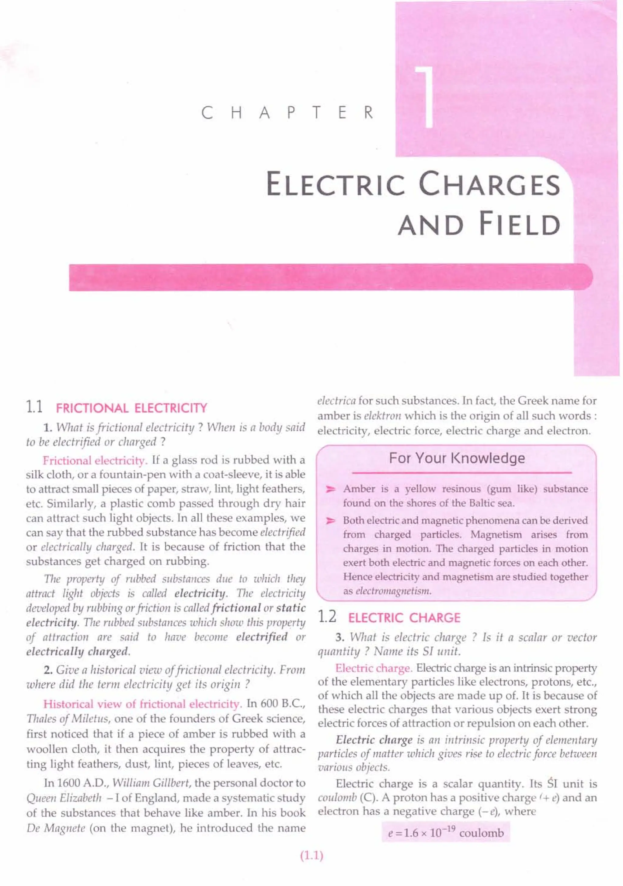
![1.2
Large-scale matter that consists of equal number of
electrons and protons is electrically neutral. If there is
an excess of electrons, the body has a negative charge
and an excess of protons results in a positive charge.
1.3 ELECTROSTATICS
4. What is electrostatics ? Mention some of its
important applications.
Electrostatics. Electrostatics is the study of electric
charges at rest. Here we study the forces, fields and
potentials associated with static charges.
Applications of electrostatics. The attraction and
repulsion between charged bodies have many indus-
trial applications. Some of these are as follows:
1. In electrostatic loudspeaker.
2. In electrostatic spraying of paints and powder
coating.
3. In flyash collection in chimneys.
4. In a Xerox copying machine.
5. In the design of a cathode-ray tube used in
television and radar.
1.4 TWO KINDS OF ELECTRIC CHARGES
5. How will you show experimentally that (i) there are
only two kinds of electric charges and (ii) like charges
repel and unlike charges attract each other ?
Two kinds of electric charges. About 100 years ago,
Charles Du Fay of France showed that electric charges
on various objects are of only two kinds. The following
simple experiments prove this fact.
EXPERIMENT
1
(i) Rub a glass rod with silk and suspend it from a
rigid support by means of a silk thread. Bring
another similarly charged rod near it. The two
rods repel each other [Fig. l.1(a)].
Silk ~ilk
Glass + Glass
++ ) t ++ J I
'JRepulslOn 1 tic ./
~ ~_p_a_5___ Attraction
~ ~
(a) (b)
~
ilk
-_ Plastic
----JRepulsion
~ (c)
Fig. 1.1 Like charges repel and unlike charges
attract each other.
PHYSICS-XII
(ii) Bring a plastic rod rubbed with wool near the
charged glass rod. The two rods attract each
other [Fig. l.1(b)].
(iii) Now rub a plastic rod with wool and suspend it
from a rigid support. Bring another similarly
charged plastic rod near it. There will be a
repulsion between the two rods [Fig. 1.1(c)].
EXPERIMENT
2. If a glass rod, rubbed with silk, is
made to touch two small pith balls (or polystyrene
balls) which are suspended by silk threads, then the two
balls repel each other, as shown in Fig. 1.2(a). Similarly,
two pith balls touched with a plastic rod rubbed with
fur are found to repel each other [Fig. 1.2(b)]. But it is
seen that a pith ball touched with glass rod attracts
another pith ball touched with a plastic rod [Fig. 1.2(c)].
(a) Repulsion (b) Repulsion
+
- -
(c) Attraction
Fig. 1.2 Like charges repel and unlike charges attract.
From the above experiments, we note that the
charge produced on a glass rod is different from the
charge produced on a plastic rod. Also the charge
produced on a pith ball touched with a glass rod is
different from the charge produced on pith ball
touched with a plastic rod. We can conclude that:
1. There areonly two kinds of electric charges - positive
and negative.
2. Like chargesrepeland unlike chargesattract eachother.
The statement 2 is known as the fundamental law
of electrostatics.
The above experiments also demonstrate-that the
charges are transferred from the rods to the pith balls
on contact. We say that the pith balls have been
electrified or charged by contact. This property which
distinguishes the two kinds of charges is called the polarity
of charge.](https://image.slidesharecdn.com/slaroraclass12thphysicsbyrockytrickster-250318042948-c8b51a5a/75/SL-ARORA-CLASS-12TH-PHYSICS-BY-ROCKY-TRICKSTER-pdf-3-2048.jpg)
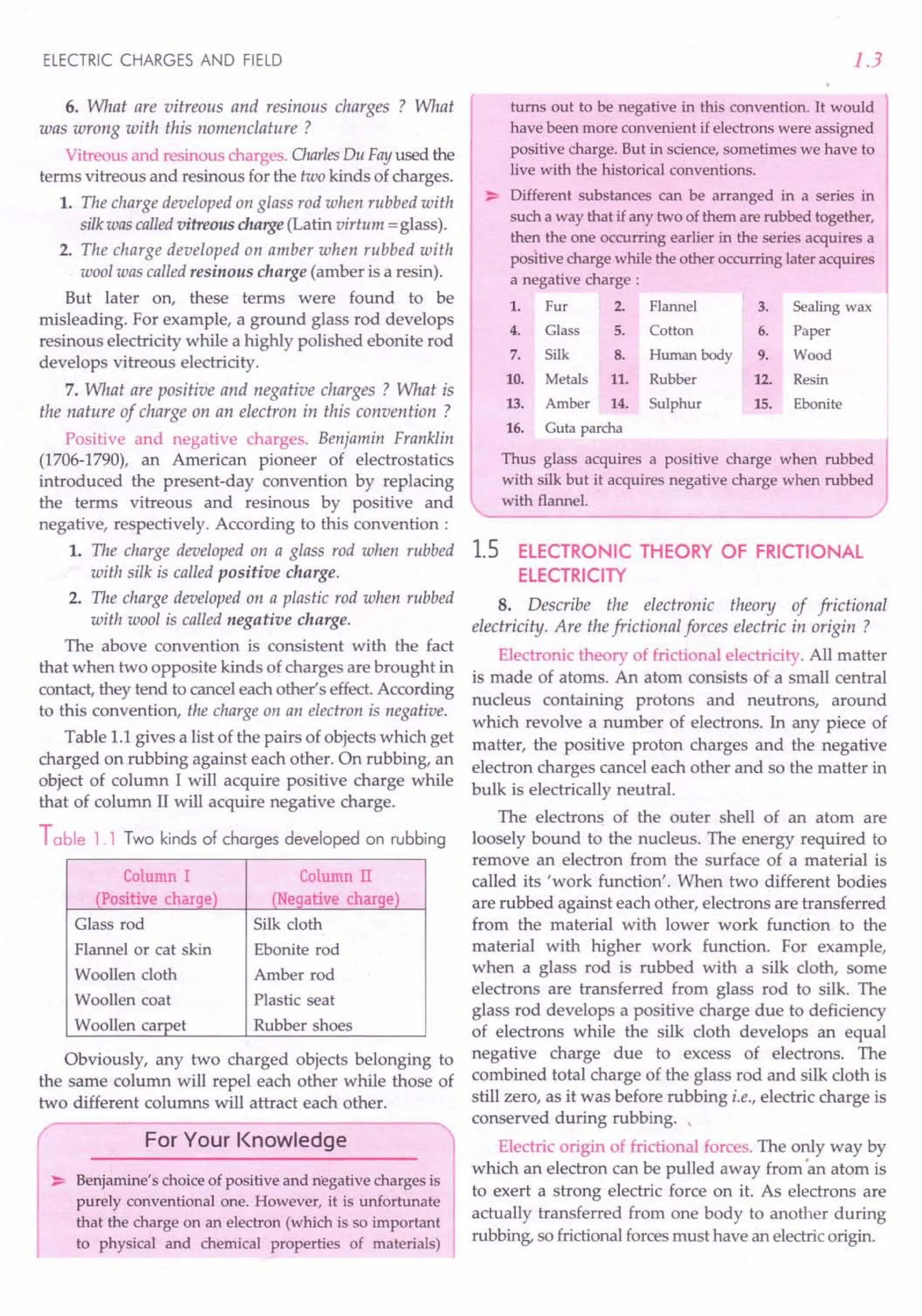
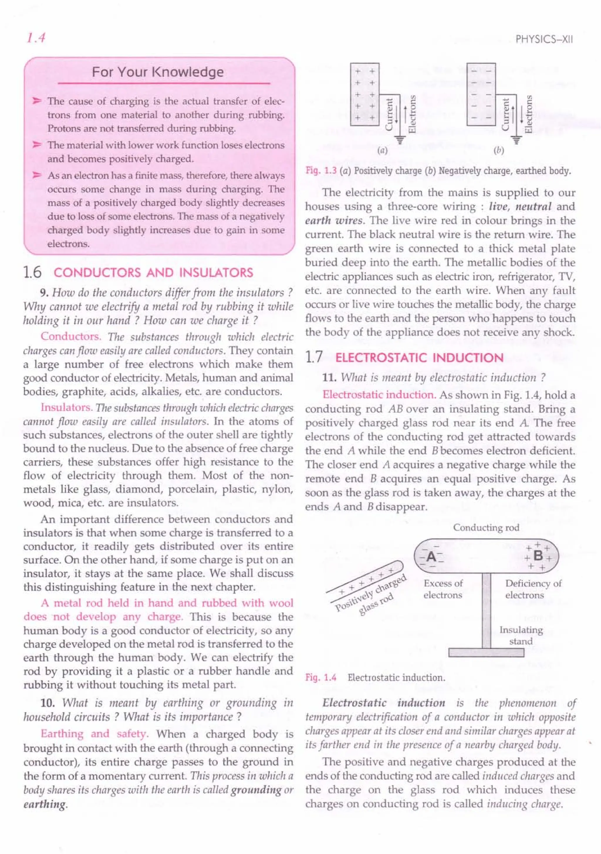
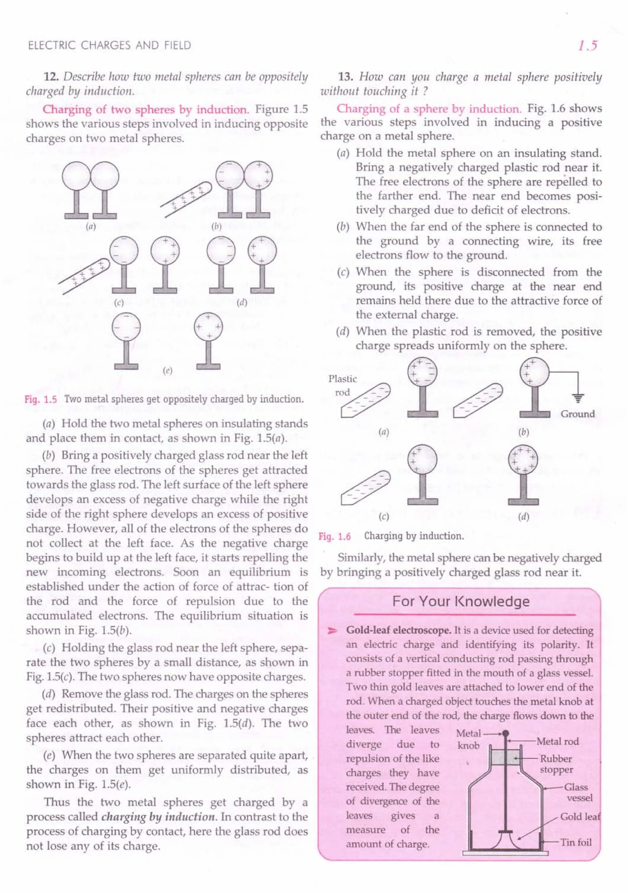
![ELECTRIC CHARGES AND FIELD
Examples based on
uanrisation of Electric Charge
Formulae Used
1. q = ne
2. Mass transferred during charging = me x n
Units Used
q and e are in coulomb, n is pure integer.
Constants Used
e = 1.6 x 10⁻¹⁹ C, me = 9.1 x 10⁻³¹ kg
Example 1. Which is bigger - a coulomb or a charge on an
electron ? How many electronic chargesform one coulomb of
charge ? [Haryana 01]
Solution. One coulomb of charge is bigger than the
charge on an electron.
Charge on one electron, e = 1.6 x 10⁻¹⁹ C
:. Number of electronic charges in 1coulomb,
q 1 C 18
n = - = = 6.25 x 10 .
e 1.6 x 10⁻¹⁹ C
Example 2. A comb drawn through person's hair on a dry
day causes 10
22
electrons to leave the person's hair and stick
to the comb. Calculate the charge carried by the comb.
Solution. Here n = 1022, e = 1.6 x 10⁻¹⁹ C
:. q = ne=1022
x 1.6 x 10-19 =1.6 x 10³ C
As the comb has excess of electrons,
:. Charge on comb = -1.6 x 10³
C.
Example 3. If a body gives out 10
9
electrons every second,
how much time is required to get a total charge of 1 Cfrom
it? [NCERT]
Solution. Number of electrons given out by the
body in one second = 109
Charge given out by the body in one second
= ne = 109 x 1.6 x 10-19 C
= 1.6 x 10- 10 C
Time required to get a charge of 1.6 x 10⁻¹⁰
C
=ls
Time required to get a charge of 1 C
1 10 S = 6.25 x 10⁹
s
1.6 x 10-
6.25 x 10
9
------ years = 198.18 years.
365 x 24 x 3600
Thus from a body emitting 109
electrons per
second, it will take nearly 200 years to get a charge of
1 C from that body. This shows how large is one
coulomb as the unit of charge.
1.7
Example 4. How much positive and negative charge is
there in a cup of water ? [NCERT]
Solution. Suppose the mass of water contained in a
cup is 250 g. The molecular mass of water is 18 g.
Number of molecules present in 18 g of water
= Avogadro's number =6.02 x 10
23
:. Number of molecules present in a cup (or 250 g)
of water
23
n = 6.02 x 10 x 250 = 8.36 x 1024
18
Each molecule of water (HzO) contains 2 + 8 = 10
electrons as well as 10 protons.
Total number of electrons or protons present in a
cup of water,
n' = n x 10 =8.36 x 1025
Total negative charge carried by electrons or total
positive charge carried by protons in a cup of water,
q = n' e
= 8.36 x 1025 x 1.6 x 10-19 C = 1.33 x 10⁷ C
rproblems For Practice
1. Calculate the charge carried by 12.5 x 10⁸ electrons.
[CBSE D 92]
(Ans. 2 x 10- 10 C)
2. How many electrons would have to be removed
from a copper penny to leave it with a positive
charge of 10-7
C ? (Ans. 6.25 x Uy1 electrons)
3. Calculate the charge on an alpha particle. Given
charge on a proton = 1.6 x 10⁻¹⁹ C.
(Ans. + 3.2 x 10⁻¹⁹ C)
4. Calculate the charge on ~ Fe nucleus. Given char~e on
a proton = 1.6 x 10⁻¹⁹ C. (Ans. + 4.16 x 10- 8 C)
5. Determine the total charge on 75.0 kg of electrons.
(Ans. - 1.33 x uP C)
6. How many mega coulombs of positive (or
negative) charge are present in 2.0 mole of neutral
hydrogen (H2) gas?
7. Estimate the total number of electrons present in
100 g of water. How much is the total negative
charge carried by these electrons ? Avogadro's
number = 6.02 x 10²³
and molecular mass of water
= 18. (Ans. 5.35 x 10⁶ C)
HINTS
3. An alpha particle contains 2 protons and 2
neutrons.
q = + 2e.](https://image.slidesharecdn.com/slaroraclass12thphysicsbyrockytrickster-250318042948-c8b51a5a/75/SL-ARORA-CLASS-12TH-PHYSICS-BY-ROCKY-TRICKSTER-pdf-8-2048.jpg)
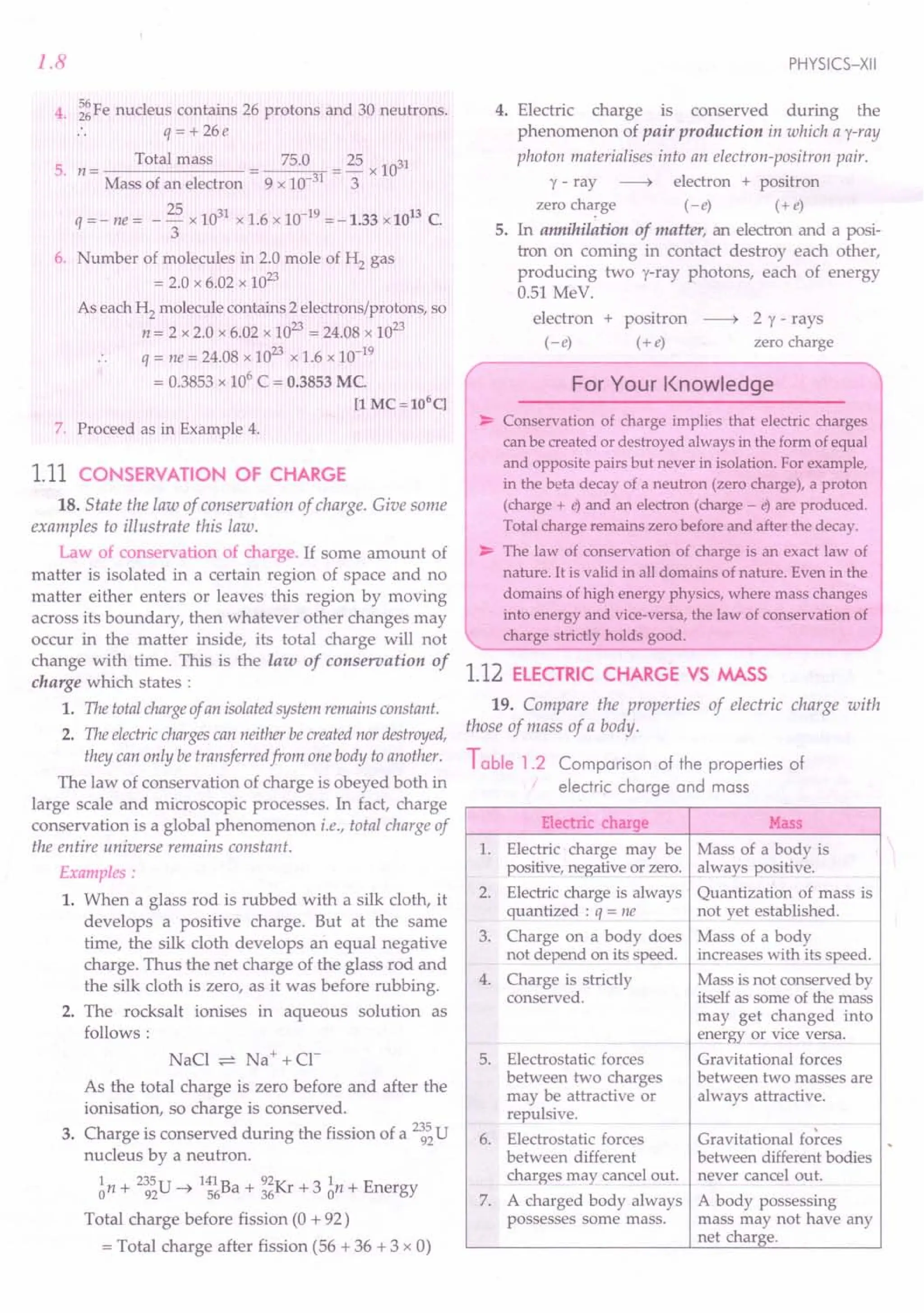
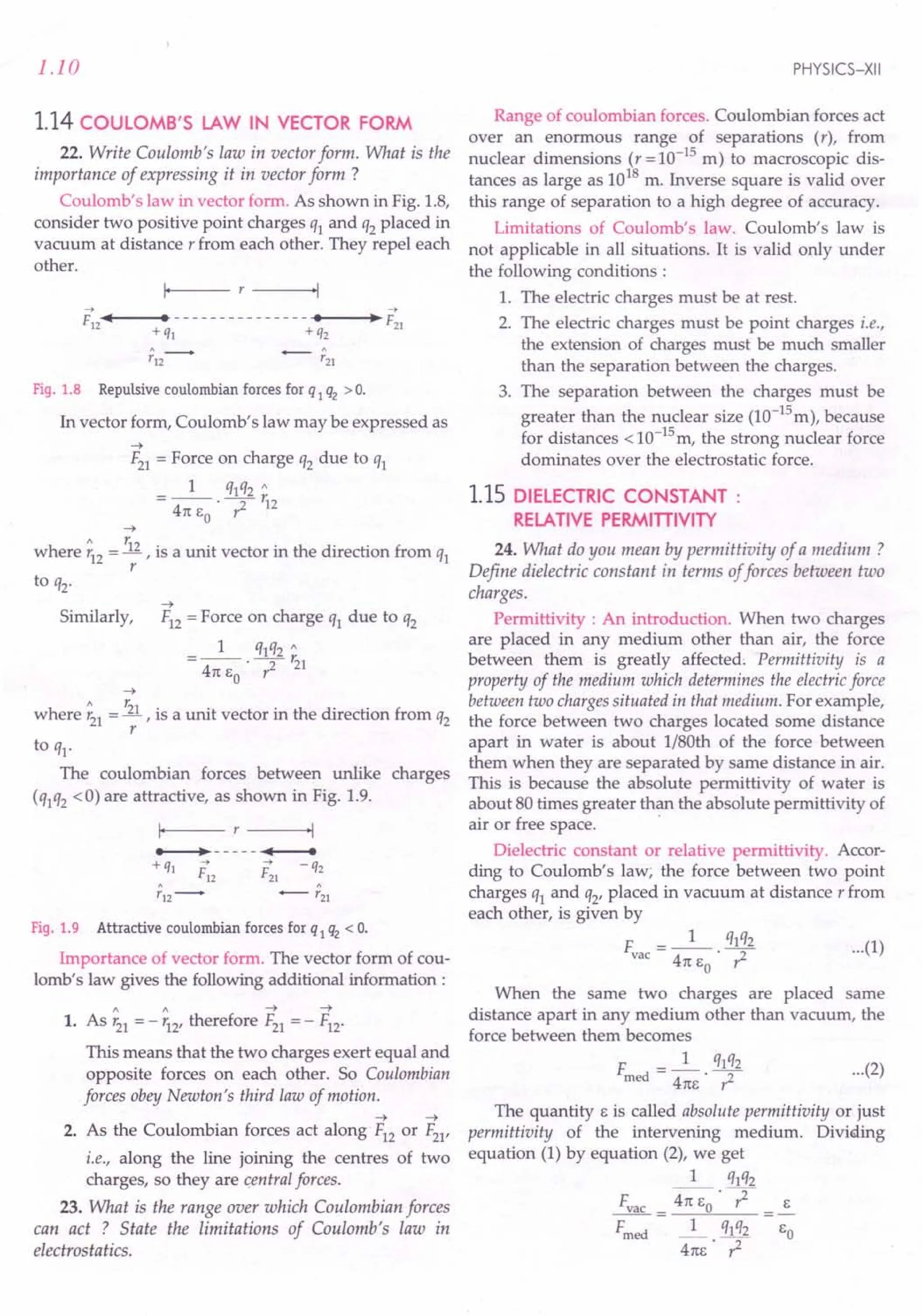
![ELECTRIC CHARGES AND FIELD
The ratio(E / EO) of thepermittivity (E) of the medium to the
permittivity (EO) of free space is called relative permittivity
(Er) or dielectric constant (K) of the given medium. Thus
E F
e, or K=-=~
EO Frned
So one can define dielectric constant in terms of
forces between charges as follows :
The dielectric constant or relative permittivity of a
medium may be defined as the ratio of theforce between two
charges placed some distance apart in free space to theforce
between the same two charges when they are placed the same
distance apart in the given medium.
Clearly, when a material medium of dielectric
constant K is placed between the charges, the force
between them becomes 1/ K times the original force in
vacuum. That is,
F = Fvac
rned K
Hence the Coulomb's law for any material medium
may be written as
K (vacuum) = 1
K (air) = 1.00054
K (water) = 80.
Formulae Used
1. t: = _1_. ql 2q2
vac 41t E r
o
2 t. __ 1_ qlq2
• rned - 41t E K r2
o
Units Used
%, q2 are in coulomb, F in newton and r in metre.
Constant Used
k = _1_ = 9 x 10⁹ Nm2c:-2
41t EO
Example 5. The electrostatic force of repulsion between two
positively charged ions carrying equal charges is~.7 x 10-9
N,
when they are separated by a distance of 5 A How many
electrons are missing from each ion ?
Solution. Here F =3.7 x 10⁻⁹ N,
r = 5 A = 5 x 10⁻¹⁰
m, ql = q2 = q (say)
As F =_1_. q1q2
41tEo ?
1.11
or
_99x109xqxq
3.7 x 10 = 10 2
(5 x 10- )
2 = 3.7 x 10-
9
x 25 x 10-
20
= 10.28 x 10-38
q 9 x 10⁹
q = 3.2 x 10⁻¹⁹ C
Number of electrons missing from each ion is
q 3.2 x 10⁻¹⁹
n=-= =2.
e 1.6 x 10⁻¹⁹
or
Example 6. A free pith-ball A of 8 g carries a positive
charge of 5 x 10⁻⁸ C. What must be the nature and
magnitude of charge that should be given to a second
pith-ball Bfixed 5 cm below theformer ball so that the upper
ball is stationary? [Haryana 01]
Solution. The pith-ball Bmust be of positive charge
i.e., of same nature as that of A, so that the upward
force of repulsion balances the weight of pith-ball A
When the pith-ball A remains F
stationary, ?
F=~g T A q)
or _1_ q1q2= mg
41tEo? - -1 5 em m)g
But ~=8g=8xlO-3kg 1 0
B q2
q1 = 5 x 10⁻⁸
C
r = 5 em =0.05 m Fig. 1.10
9 x 109
x 5 x 10-8 x q2 -3
------;;-2--= =8x 10 x 9.8
(0.05)
8 x 9.8 x {0.05l x 10- 4
q2 = 9 x 5
or
= 4.36 x 10⁻⁷ C (positive).
Example 7. A particle of mass m and carrying charge - q1
is moving around a charge + q2 along a circular path of
radius r. Prove that the period of revolution of the charge - q1
about + q2 is given by
r--=----:-
161t3 E mr3
T= 0
q1q2
Solution. Suppose charge - q1 moves around the
charge + q2 with speed v along the circular path of
radius r. Then
Force of attraction between the two charges
= Centripetal force
1 q1q2_ mv2
or 41tEo 7 --r- or
_1_ q1q2
41tEo mr
v=](https://image.slidesharecdn.com/slaroraclass12thphysicsbyrockytrickster-250318042948-c8b51a5a/75/SL-ARORA-CLASS-12TH-PHYSICS-BY-ROCKY-TRICKSTER-pdf-12-2048.jpg)
![1.12
The period of revolution of charge - ql around + q2
will be
Example 8. Two particles, each having a mass of 5 g and
charge 1.0 x 10⁻⁷
C , stay in limiting equilibrium on a
horizontal table with a separation of 10 em between them.
The coefficient offriction between each particle and the table
is the same. Find !.L
Solution. Here ql = q2 = 1.0 x 10⁻⁷
C,
r=10 em =0.10 m, m=5 g=5 x 10⁻³
kg
The mutual electrostatic force between the two
particles is
q q 9 x 109 x (1.0 x 10-7)2
F = k ~ 2 = 0.009 N
r (0.10)
The limiting force of friction between a particle and
the table is
f =!l x mg =!l x 5 x 10-3
x 9.8 =0.049 !l N
As the two forces balance each other, therefore
0.049 !l = 0.009
= 0.009 = O.lB.
!l 0.049
or
Example 9. (a) Two insulated charged copper spheres A
and B have their centres separated by a distance of 50 cm.
What is the mutual force 1,electrostatic repulsion if the
charge on each is 6.5 x 10- C? The radii of A and Bare
negligible compared to the distance of separation. Also
compare this force with their mutual gravitational attraction
if each weighs 0.5 kg.
(b) What is the force of repulsion if (i) each sphere is
charged double the above amount, and the distance between
them is halved; (ii) the two spheres are placed in water ?
(Dielectric constant of water = 80). [NCERT]
Solution. (a) Here ql = q2 =6.5 x 10⁻⁷
C,
r = 50 em. =0.50 m
Using Coulomb's law,
F. = k. qlq2
air r2
= 9 x 10⁹. 6.5 x 10-
7
x 6.5 x 10-
7
N
(0.50)2
= 1.5 x 10⁻²
N.
The mutual gravitational attraction,
F =G~""2
e R2
6.67 x 10-
11
x 0.5 x 0.5 = 6.67 x 10⁻¹¹ N
(0.5)2
Clearly, Fe « ~ir .
PHYSICS-XII
(b) (i) When charge on each sphere is doubled, and
the distance between them is halved, the force of
repulsion becomes
F'. =k.2ql·2q2 =16k.q1q2
arr (r / 2)2 r2
= 16 x 1.5 x 10-2 = 0.24 N.
(ii) The force between two charges placed in a
medium of dielectric constant K is given by
F =_1_ ! qlq2
4m,o· K· r2
For water, K = 80
F = ~ir = 1.5 x 10- 2
water K 80
. =1.875 x 10⁻⁴
N=-1.9 x 10⁻⁴
N.
Example 10. Suppose thespheresA and B in Example 9 have
identical sizes. A third sphere of the same size but uncharged
is brought in contact with thefirst, then brought in contact
with the second, and finally removed from both. What is the
new force of repulsion between A and B ? [NCERT]
Solution. Charge on each of the spheres A and B is
q=6.5xlO~7C
When a similar but uncharged sphere C is placed in
contact with sphere A, each sphere shares a charge
q/ 2, equally.
q Charge = 0 q/2 q/2
o + @ ---. GX9
q q12 3q/43q/4
0+@---'~
«n 3q/4
AO--'---OB
Fig. 1.11
Now when the sphere C (with charge q/ 2) is placed
in contact with sphere B (with charge q), the charge is
redistributed equally, so that
Charge on sphere B or C =! (q + 1)= 3q
2 2 4
•. New force of repulsion between A and B is
3q q
F=_l_ 4·2"
41tEo· ,2
= ~ x 1.5 x 10⁻²
N = 0.5625 x 10⁻²
N
8
=- 5.7 x 10⁻³
N.
Example 11. Two similarly equally charged identical metal
spheres A and B repel each other with aforce of 2.0 x 10⁻⁵ N.
A third identical uncharged sphere C is touched to A, then
placed at the midpoint between A and B. Calculate the net
electrostatic force on C. [CBSE 00 03]](https://image.slidesharecdn.com/slaroraclass12thphysicsbyrockytrickster-250318042948-c8b51a5a/75/SL-ARORA-CLASS-12TH-PHYSICS-BY-ROCKY-TRICKSTER-pdf-13-2048.jpg)
![ELECTRIC CHARGES AND FIELD
Solution. Let the charge on each of the spheres A
and B be q. If the separation between A and B is r, then
electrostatic force between spheres A and B will be
2
F = k . q2 =2.0 x 10⁻⁵ N
r
When sphere C is touched to A, the spheres share
charge q 12 each, because both are identical.
Force on C due to A
(qI2)2 q2
=k --=k- alongAC
. (r 12)2 ,2 ,
Force on C due to B
-k q.ql2 -k 2q2 I BC
- . (rI2)2 - '7' aong
Since these forces act in opposite directions,
therefore net force on C is
, 2 q2 q2 q2 -5
F = k . -2 - k . 2" = k 2" = 2.0 x 10 N, along Be.
r r r
Example 12. Two identical charges, Q each, are kept at a
distance rfrom each other. A third charge q is placed on the
line joining the above two charges such that all the three
charges are in equilibrium. What is the magnitude, sign and
position of the charge q ? [CBSE OD 94, 98]
Solution. Suppose the three charges be placed in
the manner, as shown in Fig. 1.12.
14 r ~I
14 x ~I B
AI I Ie
Q q Q
Fig. 1.12
The charge q will be in equilibrium if the forces
exerted on it by the charges at A and C are equal and
opposite.
k Qq=k ~
. x2 . (r-x)2
or
or x=r-x
r
x=-
2
or
Since the charge at A is repelled by the similar
charge at C, so it will be in equilibrium if it is attracted
by the charge q at B, i.e., the sign of charge q should be
opposite to that of charge Q.
Force of repulsion between charges at A and C
= Force of attraction between charges
at A and B
k ~=k Q.Q or q= Q.
(r 12)2,2 4
or
Example 13. Two point charges + 4e and + e are 'fixed' a
distance 'a' apart. Where should a third point charge q be
placed on the line joining the two charges so that it may be in
1.13
equilibrium ? In which case the equilibrium will be stable
and in which unstable ?
Solution. Suppose the three charges are placed as
shown in Fig. 1.13. Let the charge q be positive.
+4e +q +e
I
• I ~ I
F2 F1
I, x ,I, a-x--l
Fig. 1.13
For the equilibrium of charge + q, we must have
Force of repulsion Fl between + 4e and + q
= Force of repulsion F2between + e and + q
1 4e x q 1 ex q
4Tc!:O ~ = 4m:o (a - X)2
4 (a - x)2 = x2
2 (a - x) = ± x
2a
x =- or 2a
3
As the charge q is placed between + 4e and + e, so
only x = 2 a 13 is possible. Hence for equilibrium, the
charge q must be placed at a distance 2al3 from the
charge + 4e.
We have considered the charge q to be positive. If
we displace it slightly towards charge e, from the
equilibrium position, then Fl will decrease and F2will
increase and a net force (F2 - F1
) will act on q towards
left i.e., towards the equilibrium position. Hence the
equilibrium of positive q is stable.
Now if we take charge q to be negative, the forces Fl
and F2will be attractive, as shown in Fig. 1.14.
or
or
or
+ 4e -q +e
I
• I ~ I
F1 F2
I, x ,I a-x--l
Fig. 1.14
The charge - q will still be in equilibrium at
x = 2 a 13. However, if we displace charge - q slightly
towards right, then Fl will decrease and F2 will
increase. A net force (F2 - F1
) will act on - q towards
right i.e., away from the equilibrium position. So the
equilibrium of the negative q will be unstable.
Example 14. Two 'free' point charges + 4e and + e are
placed a distance 'a' apart. Where should a third point charge
q be placed between them such that the entire system may be
in equilibrium? What should be the magnitude and sign of q ?
What type of a equilibrium will it be ?](https://image.slidesharecdn.com/slaroraclass12thphysicsbyrockytrickster-250318042948-c8b51a5a/75/SL-ARORA-CLASS-12TH-PHYSICS-BY-ROCKY-TRICKSTER-pdf-14-2048.jpg)
![1.14
Solution. Suppose the charges are placed as shown
in Fig. 1.15.
+4e -q +e
. ~ .
III
• ~ III
F F' F1
I, x
I,
F2
---ojo·I·>--a - x------l
a .1
Fig. 1.15
As the charge + e exerts repulsion F on charge + 4e,
so for the equilibrium of charge +4e, the charge - q
must exert attraction F' on +4e. This requires the
charge q to be negative.
For equilibrium of charge + 4e,
F = F'
1 4e x e 1 4e x q
411:Eo ----;;r = 411:Eo ~
ex2
q=-
a2
For equilibrium of charge - q,
Attraction F1between + 4e and - q
= Attraction F2between + e and - q
1 4e x q 1 ex q
.. 411:Eo ~ = 411:Eo (a - x)2
x2 =4(a _x)2
x =2a/3
ex2 e 4a2 4e
q=-=- -=-
a2 a2' 9 9'
The equilibrium of the negative charge q will be
unstable.
or
or
Hence
Example 15. Two point charges of charge values Q and q
are placed at distances x and x /2 respectively from a third
charge of charge value 4q, all charges being in the same
straight line. Calculate the magnitude and nature of charge
Q, such that the netforce experienced by the charge q is zero.
[CBSE D 98].
Solution. Suppose the three charges are placed as
shown in Fig. 1.16.
~ q Q
• III· ~ •
A F8 C FA B
Fig. 1.16
For the equilibrium of charge q, the charge Q must
have the same sign as that of q or 4q , so that the forces
FA and FBare equal and opposite.
As FA = FB
1 4qx q 1 qx Q
411:Eo' (x/2)2 = 411:Eo' (x/2)2
Q=4q.
or
PHYSICS-XII
Example 16. A charge Q is to be divided on two objects.
What should be the values of the charges on the two objects
so that the force between the objects can be maximum ?
Solution. Let q and Q - q be the charges on the two
objects. Then force between the two objects is
F=_I_ q(Q-q)
411:EO . ,2
where r is the distance between the two objects.
For F to be maximum,
dF =0
dq
1 .~.~(qQ_q2)=0
411:EO ,2 dq
~ (qQ _ q2) = 0
dq
Q -2q =0
q= Q
2
or
or
or
or
i.e., the charge should be divided equally on the two
objects.
Example 17. Two identical spheres, having charges of
opposite sign attract each other with aforce of 0.108 Nwhen
separated by 0.5 m. The spheres are connected by a conduc-
ting wire, which then removed, and thereafter they repel each
other with aforce of 0.036 N. What were the initial charges
on the spheres ?
Solution. Let + q1and - q2be the initial charges on
the two spheres.
(a) When the two spheres attract each other,
F = k q1~2 i.e., 0.108 =9 x 10⁹. q1q22
r: (0.5)
= 0.108 x (0.5)2 =3 x 10 -12
q1q2 9 x 10⁹
(b) When the two spheres are connected by the
wire, they share the charges equally.
q + (- q) q - q
:. Charge on each sphere = 1 2 = _1
__ 2
2 2
i.e.,
Force of repulsion between them is
F= k(¥)(¥)
,2
0.036 = 9 x 10
9
. (q1 - q2)2
(0.5)2 2
( _ )2 = 0.036 x (0.5)2 x 4 = 4 x 10-12
.. q1 q2 9 x 10⁹
q1 -q2 =2 x 10⁻⁶
...(i)
or](https://image.slidesharecdn.com/slaroraclass12thphysicsbyrockytrickster-250318042948-c8b51a5a/75/SL-ARORA-CLASS-12TH-PHYSICS-BY-ROCKY-TRICKSTER-pdf-15-2048.jpg)
![ELECTRIC CHARGES AND FIELD
Now (q1 + q2)2 = (q1 - q2)2 + 4q1q2
= (2 x 10⁻⁶)2 + 4 x 3 x 10-12
= 16 x 10-12
q1+ q2 = 4 x 10⁻⁶
... (ii)
On solving equations (i) and (ii), we get
q1 = 3 x 10⁻⁶
C and q2 = 10-6
C
which are the initial charges on the two spheres.
Example 18. Two small spheres each having mass m kg
and charge q coulomb are suspended from a point by
insulating threads each Imetre long but of negligible mass. If
a is the angle, each thread makes with the vertical when
equilibrium has been attained, show that
q2 = (4 mgl2 sin2
a tan a) 4n EO [Punjab 95]
Solution. The given situation is shown in Fig. 1.17.
Each of the spheres A and B is acted upon by the
following forces:
(i) its weight mg, (ii) tension T in the string
(iii) the force of repulsion F given by
1 q2
F = -- . -----:::i ... (i)
4n EO Alj-
o
~~'
,
,
F~i--------c ---------
"
mg
Fig. 1.17
As the forces are in equilibrium, the three forces on
sphere A can be represented by the three sides of
t!. AOC taken in the same order. Hence
~= mg =~
AC OC AO
AC
or F = mg x - ... (ii)
OC
From (i) and (ii), we have
1 q2 AC
--.--=mgx-
4nEo AW OC
But AC = I sin a, OC = I cas a, AB =2 AC =21 sin a
1 q2 I sin a
--. =mgx--
4n EO 412 sin2
a I cos a
or q2 = (4 mg 12 sin2
a tan a) 4n EO'
1.15
~rOblems For Practice
1. Obtain the dimensional formula of EO'
(Ans. M-1
L-3
T4
A2)
2. Calculate coulomb force between two a-particles
separated by a distance of 3.2 x 10⁻¹⁵ m in air.
[CBSE 00 92]
(Ans. 90 N)
3. Calculate the distance between two protons such
that the electrical repulsive force between them is
equal to the weight of either. [CBSE 0 94]
(Ans. 1.18 cm)
4. How far apart should the two electrons be, if the
force each exerts on the other is equal to the weight
of the electron ? Given that e = 1.6 x 10⁻¹⁹
C and
me = 9.1 x 10⁻³¹ kg. [Haryana 02]
(Ans. 5.08 m)
5. A pith-ball A of mass 9 x 10⁻⁵ kg carries a charge of
5fie. What must be the magnitude and sign of the
charge on a pith-ball B held 2 em directly above the
pith-ball A, such that the pith-ball A remains
stationary ?
(Ans. 7.84 pC, sign opposite to that of A)
6. Two identical metal spheres having equal and
similar charges repel each other with a force of
103 N when they are placed 10 em apart in a medium
of dielectric constant 5. Determine the charge on
each sphere. (Ans. 23.9 x 10⁻⁶ C)
7. The distance between the electron and proton in
hydrogen atom is 5.3 x 10⁻¹¹
m. Determine the magni-
tude of the ratio of electrostatic and gravitational
force between them.
Given me = 9.1 x 10⁻³¹
kg, mp = 1.67 x 10⁻²⁷ kg,
e = 1.6 x 10⁻¹⁹
C and G = 6.67 x 10⁻¹¹
Nm 2 kg-2.
(Ans. Fe / Fc = 2.27 x 1039
)
8. Two identical metallic spheres, having unequal,
opposite charges are placed at a distance 0.90 m
apart in air. After bringing them in contact with
each other, they are again placed at the same
distance apart. Now the force of repulsion between
them is 0.025 N. Calculate the final charge on each
of them. [CBSE D 02C]
(Ans. 1.5 x 1O-6q
9. A small brass sphere having a positive charge of
1.7 x 10⁻⁸ C is made to touch another sphere of the
same radius having a t;legativecharge of 3.0 x 10⁻⁹
e.
Find the force between them when they are
separated by a distance of 20 cm. What will be the
force between them when they are immersed in an
oil of dielectric constant 3 ?
(Ans. 1.1 x 10⁻⁵ N; 0.367 x 10⁻⁵ N)](https://image.slidesharecdn.com/slaroraclass12thphysicsbyrockytrickster-250318042948-c8b51a5a/75/SL-ARORA-CLASS-12TH-PHYSICS-BY-ROCKY-TRICKSTER-pdf-16-2048.jpg)
![1.16
10. The sum of two point charges is 71lC. They repel
each other with a force of 1 N when kept 30 ern
apart in free space. Calculate the value of each
charge. [CBSE F 091
(Ans. 51lC, 21lC)
11. Two point charges q1 = 5 x 1O-6
C and q2 = 3 x 1O-6
C
are located at positions (1 m, 3 rn, 2 m) and (3 rn,
~ ~
5 m, 1 m) respectively. Find the forces li2 and F21
using vector form of Coulomb's law.
---t 3 1 / 1
[AnS.li2 = -5xl0- (2i + 2j -k)N,
---t 3 1 / 1
F21 = svro: (2i + 2j -k)N]
12. Three equally charged small objects are placed as
shown in Fig. 1.18. The object A exerts an electric
force on object B equal to 3.0 x 1O-6
N.
A B C
• • • 3.
14 2cm ~14 1em ----+I
Fig. 1.18
(i) What electric force does C exert on B?
(ii) What is the net electric force on B?
[Ans. (i) 12.0 x 10⁻⁶
N, along BA
(ii) 9.0 x 10⁻⁶
N, along BAl
13. Two identical metallic spheres A and B,each carry-
ing a charge q, repel each other with a force F. A
third metallic sphere C of the same size, but un-
charged, is successively made to touch the spheres
A and B,and then removed away. What is the force
of repulsion between A and B? (Ans. 3F /8)
14. Two point charges + ge and +e are kept at a distance
a from each-other. Where should we place a third
charge q on the line joining the two charges so that
it may be in equilibrium ?
(Ans. 3: from + ge Charge)
15. Two point electric charges of values q and 2q are
kept at a distance d apart from each other in air. A
third charge Q is to be kept along the same line in
such a way that the net force acting on q and 2q is
zero. Calculate the position of charge Qin terms of q
and d. [CBSE D 98]
(Ans. At a distance of (..fi - 1) d from charge q)
16. A charge q is placed at the centre of the line joining
two equal charges Q. Show that the system of three
charges will be in equilibrium if q = -Q/ 4.
[CBSE OD 05]
17. Two pith-balls each weighing 10-3kg are
suspended from the same point by means of silk
PHYSICS-XII
threads 0.5 m long. On charging the balls equally,
they are found to repel each other to a distance of
0.2 m. Calculate the charge on each ball.
[Haryana 2002]
(Ans. 2.357 x 10- 6 C)
HINTS
1. F = _1_ . q1 :}2 or EO
= lit q2
2
41tEo r 41tFr
[E 1= AT. AT = [~lL-3T4 A2l.
o MLT2. L2
2. Here q1 = q2 = 2e = 3.2 x 10⁻¹⁹C, r = 3.2 x 10⁻¹⁵ m
F= _1_ lItq2
41tEo' r2
9 x 109 x 3.2 x 10-19 x 3.2 x 10-19
----------~,_------90N
(3.2 x 10 15)2 -.
For a proton, m = 1.67 x 10⁻²⁷ kg,
q = + e = 1.6 x 10⁻¹⁹C.
Weight of proton = Electrical repulsive force
q x q
mg = k.--2
-
r
9 x 109
x(1.6 x 10-19)2
1.67 x 10 27 x 9.8
or
r2 = kq2
mg
= 23.04 x 10-2 = 0.014
16.36
or r = 0.0118 m = 1.18 em.
exe
4. me g = k . --2-
r
or
9 x 109 x(1.6 x 10-19)2
_____ '---,,.- __ --C- = 25.84
9.1 x 10 31x 9.8
r= 5.08 m.
5. The pith-ball B must have charge opposite to that of
A so that the upward force of attraction balances
the weight of pith-ball A.
When the pith-ball A remains
stationary, T
Q20B
2r~A
Q)
m)g
or
F = rr;g
_1_ q1 q2 = rr; g
41tEO r2
rr; = 9 x 10⁻⁵ kg,
q1 = 51lC = 5 x 10⁻⁶ C,
r= 2cm =0.02 m
9x109x5xlO-6xq2 -5
--------"2,-----'= = 9 x lOx 9.8
(0.02)
q2 = 7.84 x 10⁻¹²C = 7.84 pc.
But
Fig. 1.19
or](https://image.slidesharecdn.com/slaroraclass12thphysicsbyrockytrickster-250318042948-c8b51a5a/75/SL-ARORA-CLASS-12TH-PHYSICS-BY-ROCKY-TRICKSTER-pdf-17-2048.jpg)
![ELECTRIC CHARGES AND FIELD
9 x 10⁹
x q2
103=---;,-
5 x (0.10)2
6. F=_l_ q1i2
41tEOK' ..
or q = 23.9 x 10⁻⁶
C.
7. Proceed as in illustrative problem on page 1.18.
8. The two spheres will share the final charge equally.
Let q be the charge on each sphere.
F= _1_. qlq2 = 0.025 N
.. 41t Eo r2
9 x 10⁹ x q x q
-----<-2 ----'-= 0.025
(0.90)
q2 = oms x (0~90)2= 225 x 10-14
9 x 10
q = 1.5 x10⁻⁶ C.
or
or
or
9. Charge shared by each sphere
= (17 - 3) x 10-
9
= 7 x 10⁻⁹ C
2
9 x 109 x(7 x 10-9)2 -5
F. = 2 =1.lx10 N
au (0.20)
9 x 109 x(7 x10-9)2 -5
E.] = 2 = 0.367 x10 N.
01 3 x (0.20)
10. Here F = 1N, r = 30 m
F=k~2
9 x 109
x 1M2
1= ------,,'-'-'-"-
(0.30)2
10-11
or q1q2=
But q1+ q2 = 7!-1C= 7x10⁻⁶ C
Now (q1 - q2)2 = (q1 + q2)2 - 4q1q2
= 49 x 10-12- 4 x 10-11
= 9 x 10-12
or q1 - q2 = 3 x 10-6 = 3!-1C
On solving (i) and (ii), we get
q1 = 5!-1C and q2 = 2!-1C.
As
-+ 1 1 1 ~ 1 1 "
11. Here 1 =(i +3j+2k )m, '2 =(3i +5j+k)m
--» -+ -+ 1 1 1 1 1 1
12 = '2-1 =(3i +5j+k )-(i +3j +2k)
-+ ~2 2 2
112 I = 2 + 2 + (-1) = 3 m
1.17
-+ 1 ~q2"
F21= -- -2- 12
41tEo 12
9x109x5x10-6x3x10-6 (2i+2J-k)
3
2
3
3 " 1 1
= 5x10- (2i +2j -k)N
-+ -+ -3 ~ <' 1
Also, li2=-Fz1=-5xlO (21+2J-k)N.
12. Here AB = 2 em = 0.02 m, Be = 1em = 0.01 m
q q q
. ... ~ .
A FBe B FBA C
I· 2 ern ·1· 1 em----l
Fig. 1.20
Let q be the charge on each object.
F __ 1_~
BA - 41tEo(AB)2
-6 9 x 10⁹ x q2
or 3.0x10 = 2
(0.02)
2 4 10-19C
or q = - x .
3
(i)
1 q x q 9 4 x 10-19
F =-----=9xlO X---"
BC 41t1,o
.(BC)2 3 x(0.01)2
= 12.0 x 10⁻⁶
N, along BA.
...(i)
(ii) Net force on charge at B,
F = FBC - FBA = (12.0 - 3.0) x 10-6
= 9.0 x10⁻⁶ N, along BA.
13. Proceed as in Example 10 on page 1.12.
14. Force between + ge and q = Force between +e and q
k gexq=k ~
.. . x2 . (a - x)2
3 1
or or x = 3a /4.
x a-x
...(ii) 15. For equilibrium of charges q and 2q, the charge Q
must have sign opposite to that of q or 2q. Suppose
it is placed at distance x from charge q.
q Q 2q
• • •
I--- x ---+1·1__
· - d - x-----1
Fig. 1.21
For equilibrium of charge q,
k qQ - k q x2q
x2 - d2
For equilibrium of charge 2q,
kqx2q=k Qx2q
d2 (d-x)2
...(i)
...(ii)](https://image.slidesharecdn.com/slaroraclass12thphysicsbyrockytrickster-250318042948-c8b51a5a/75/SL-ARORA-CLASS-12TH-PHYSICS-BY-ROCKY-TRICKSTER-pdf-18-2048.jpg)
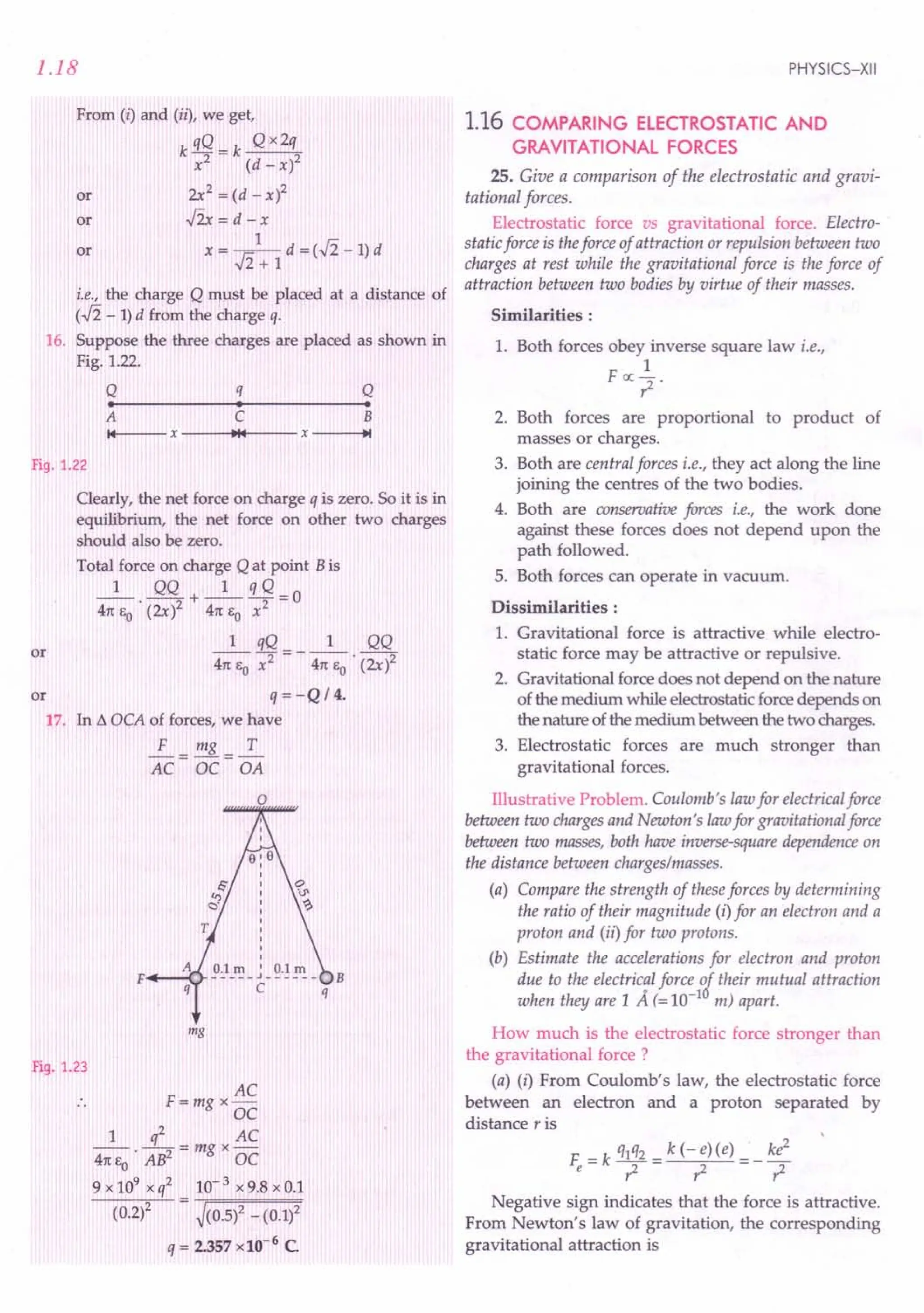
![1.20
y
o·~~=-----------------------~X
Fig. 1.24 Superposition principle: Force on
charge ql exerted by qz and q3'
According to Coulomb's law, the force exerted on
charge ql due to q2 is
~ 1 qlq2"
F ----- t:
12 - 4m; T!: 12
o 12
~ ~
1 qlq2 r1 - r2
4m; . ~ ~ 2' ~ ~
o Ir1-r21 Ir1-r21
or
or
~ ql
F =--
1 41tE
o
~ ~
In general, force Faon ath charge qa located at radue
to all other (N -1) charges may be written as
PHYSICS-XII
~
Fa = Total force on ath charge
~ q Nq" q N ti
F = _a_ L i rab= _a_ L qb a - b
41tEo b= 1 ~b 41tEO b= lit _
i 13
b"a b"a a b
where a = 1,2, 3, ..., N.
It may be noticed that for each choice of a, the
summation on b omits the value a. This is because
summation must be taken only over other charges. The
above expression can be written in a simpler way as
follows:
~
F = Total force on charge q due to many point
charges c(
F=-q- L c(
41tEo all point
charges
~ ~
r - r'
~ ~3
1 r - r' 1
Examples based on
Principle ofl,Superposition ~7. " :
of Electric'Forces .' . ' ',.;;.
Formulae Used
~ ~ ~ ~ ~
Fl = F12+ F13+ F14 + ...+ FIN
F = ~ Fl + F22+ 2 Fl F2 cos o
Units Used
Forces are in newton, charges in coulomb and
distances in metre.
Example 19. An infinite number of charges each equal to
4 IlC are placed along x-axis at x = 1 m, x = 2 m, x = 4 m,
x = 8 m and so on. Find the total force on a charge of 1 C
placed at the origin. [lIT 95]
Solution. Here q = 4 IlC = 4 x 10⁻⁶
C, qo = 1 C
By the principle of superposition, the total force
acting on a charge of 1C placed at the origin is
- qqo [1 1 1 1
F - 41tEo ,; + tf + -1 + ...
= 9 x 109
x 4 x 10- 6 x 1 [ ~ + ~ + ~ + ...]
1 2 4
Sum of the infinite geometric progressio~
a 1 4
1-r = 1-!='3
4
F = 9 x 109
x 4 x 10-6
x i = 4.8 x 10⁴
N.
3](https://image.slidesharecdn.com/slaroraclass12thphysicsbyrockytrickster-250318042948-c8b51a5a/75/SL-ARORA-CLASS-12TH-PHYSICS-BY-ROCKY-TRICKSTER-pdf-21-2048.jpg)
![ELECTRIC CHARGES AND FIELD
Example 20. Consider three charges ql' q2'q3each equal to
qat the vertices of an equilateral triangle of side I. What is the
force on a charge Q (with the same sign as q) placed at the
centroid of the triangle ? [NCERT]
Solution. Suppose the given charges are placed as
shown in Fig. 1.2S(a).
A
ql
"[;?"O
AO
"
BO
(a) (b)
Fig. 1.25
Let AO= BO=CO=r
Force on charge Q due to ql'
F =_1_ Qql AD
14m, A02
o
Force on charge Q due to q2'
F =_1_ Qq2 B"o
.c.:> 2 4m,o B02
Force on charge Q due to q3'
F =_1_ Qq3 CD
3 4m,o C02
By the principle of superposition, the total force on
charge Q is
----+ ----t ----t ----t
F=Ji+Fz+F3
= ~ [AD + B"o + CD] [.,' lh = q2 = q3 = q]
4m,o r
As shown in Fig. 1.2S(b), the angle between each
"" "
pair of the unit vectors AO, BO and CO is 120°, so they
form a triangle of cyclic vectors. Consequently,
" " "
AO+ BO+ CO=O
~
Hence F =0 i.e., the total force on charge Qis zero.
Example 21. Three point charges +q each are kept at the
vertices of an equilateral triangle of side '1'. Determine the
magnitude and sign of the charge to be kept at its centroid so
that the charges at the vertices remain in equilibrium.
[CBSE F 2015]
Solution. At any vertex, the charge will be in
equilibrium if the net electric force due to the
remaining three charges is zero.
1.21
I
I
Fig. 1.26
Let Q be the charge required to be kept at the
centroid G.Then,
-4
Ji = Force at A due to the charge at B
1 2 ~
=--!L,along BA
4m,o 12
-4 1 2 -4
Fz= Force at A due to charge at C = --. q2' along CA
4m,o I
~ -4 -4 1 q2 -4
Ji+ F2= 2Ji cos30°, along GA = .Ji--·2, along GA
41teo I
Force at A due to charge at C
1 Qq 1 Qq
4nEo' AC2 = 4nEo' (l / .J3)2
1 3Qq
4nEo'[2
~ ~
This must be equal and opposite to (Fl + F2).
•. 3Qq=-.J3q2 or Q=- ~.
Example 22. Consider the charges q, q and - q placed at
the vertices of an equilateral triangle, as shown in Fig. 1.27.
What is the force on each charge ? [NCERT)
Solution. The forces of attraction or repulsion
between different pairs of charges are shown in
Fig. 1.27. Each such force has magnitude,
1 q2
F=-- -
4nE
o
' 12
q3=-q
F F
r
r
r
r
Fig. 1.27](https://image.slidesharecdn.com/slaroraclass12thphysicsbyrockytrickster-250318042948-c8b51a5a/75/SL-ARORA-CLASS-12TH-PHYSICS-BY-ROCKY-TRICKSTER-pdf-22-2048.jpg)
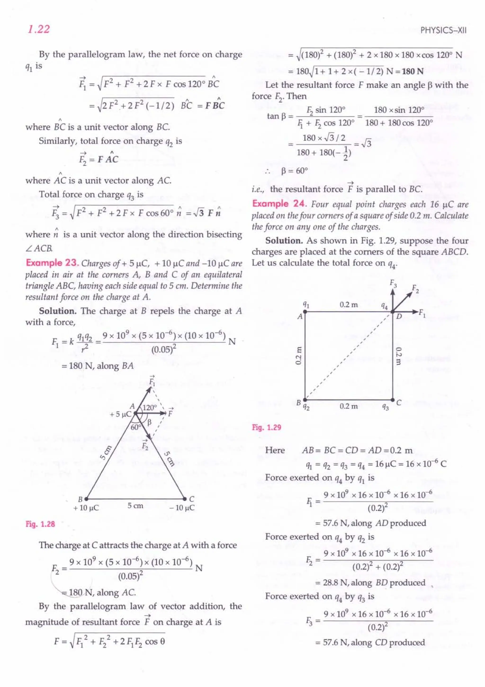
![Solution. As shown in Fig. 1.30(b), the force exerted
on charge +2 IlCby charge at B,
F =_1_ q1q2
1 4rc EO 1-
9 x 109 x 2 x 10-6 x 3 x 10-6
(0.20)2
= 1.35 N, along AB
Force exerted on charge +2 IlCby charge at C,
9 x 109 x 2 x 10-6 x 3 x 10-6
F - --------;;,,.-----
2 - (0.20)
= 1.35 N, along AC
Resultant force of 1iand Fz
F = ~rF-=lo...+-F2::-2
-"+'--2-F-
1
-F-
1
-co-s-6-0-0
= ~1.352 + 1.352 + 2 x 1.35 x 1.35 x 0.5
= 1.35 x .J3 =2.34 N, along AM
For the charge at A to be equilibrium, the charge q to
be placed at point M must be a positive charge so that it
exerts a force on +21lC charge along MA.
Now, AM = ~202 _102
=.J300 =10.J3 em
= 0.1 x .J3 m Fig. 1.32
ELECTRIC CHARGES AND FIELD
As F1 and F3 are perpendicular to each other, so
their resultant force is
F' = ~r-li-=-2
-+-I;-=-2 = ~57.62 + 57.62
= 57.if2 = 81.5N, in the direction of Fz.
Hence total force on q4 is
F = F2+ F' = 28.8+ 81.5
= 110.3 N, along BD produced.
Example 25. Three point charges of +2 1lC,-3 IlC and
-3 IlC are kept at the vertices A, Band C respectively of an
equilateral triangle of side 20 cm as shown in Fig. 1.30(a).
What should be the sign and magnitude of the charge to be
placed at the midpoint (M) of side BC so that the charge at A
remains in equilibrium ? [CBSE 0 05]
+2J.lC
-3J.lC~~ ~~~
B--- 20cm- C B
-3 J.lC -3 J.lC
(a)
M
(b)
Fig. 1.30
1.23
Net force on charge at A will be zero if
9 x 10⁹ x q x 2 x 10⁻⁶
----'-:=-:::--- = 2.34
(0.1x .J3)2
_ 2.34 x 0.01 x 3 -39 10-6 C - C
or q - 3 -. x - 3.91l •
18 x 10
rproblems for Practice
1. Ten positively charged particles are kept fixed on
the x-axis at points x = 10 em, 20 em, 40 em, ...r
100 em. The first particle has a charge 1.0 x 10⁻⁸ C,
the second 8 x 10⁻⁸ C, third 27 x 10-8 C, and so on.
The tenth particle has a charge 1000x 10-8 C. Find
the magnitude of the electric force acting on a 1 C
charge placed at the origin. (Ans. 4.95x 10⁵N)
2. Charges I1J. = 1.5 mC, q2 = 0.2 mC and q3 = - 0.5 mC
are placed at the points A, B and C respectively, as
shown in Fig. 1.31. If 1= 12 m and r2= 0.6 m,
calculate the magnitude of resultant force on q2.
(Ans. 3.125x 10³ N)
F2
B
A F}
q} q2
Fig. 1.31
3. Two equal positive charges, each of 21lC interact
with a third positive cHarge of 3 IlC situated as
shown in Fig. 1.32. Find the magnitude and
direction of the force experienced by the charge of
3 1lC. (Ans. 3.456x 10⁻³ N, along DC produced)
A
.,2 J.lC
1 ,
1
1
I
I
3m; "
; " 3 J.lC
1 '
01- - - - - - - - - - - - - - _':-·C
; 4m -:
I
1
3m;
1
I
I
I ,
·'2J.lC
B](https://image.slidesharecdn.com/slaroraclass12thphysicsbyrockytrickster-250318042948-c8b51a5a/75/SL-ARORA-CLASS-12TH-PHYSICS-BY-ROCKY-TRICKSTER-pdf-24-2048.jpg)
![1.24
4. Four charges + q , + q , -q and -q are placed respec-
tively at the four corners A, B,Cand Dof a square of
side a. Calculate the force on a charge Q placed at
the centre of the square.
[
Ans. _1_ 4fipq ,parallel to ADor BC]
41t1,o a
HINTS
1. By the principle of superposition, the total force on
the 1C charge placed at the origin is
Fo = FOl + F02 + F03 + ....+ lio
= 3.L [ql + q2 + q~ + ....+ ql0]
41t Eo rf ri'3 1{0
9 [ 1.0 x 10⁻⁸
8 x 10-8
=lx9xlO +--..-
(0.10)2 (0.20)2
27 x 10-8
1000 x 10-8
]
+ (0.30)2 + ...+ (1.00)2
= 9 x 109
x 10-6 [1+ 2 + 3 + ...+ 10]
= 9 x55 x 103
= 4.95 x10
s
N.
1 ~q2 9 x 109
x 0.2 x 10-3
x 9 x 109
2. li = 41tEo -;; = (1.2)2
= 1.875 x 10³
N, along AB produced
E __ 1_ q2q3 9 x 109
x 0.2 x 10-3
x 0.5 x 10-3
2 - 41tEo' ,i (0.6)2
= 2.5 x 10³ N, along BC..l. AB
As li ~ the resultant force on q2 is
~2 + F22 = 3.125 x 10³
N.
3. Here qA = qB = 2 J.lC= 2 x 10- 6 C,
qc = 3 J.lC= 3 x 10- 6 C
AC= BC=~32 + 42
=5m
I
I
I
I
I
I
3m:
: 4m e
O~------------
: e
I
I
3m:
I
I
I
qB I
B
Fig. 1.33
Force exerted by charge qA on 'ic-
F - _1_ qA qc
A - 41tEo (AC)2
PHYSICS-XII
9 x 109 x 2 x 10-6 x 3 x 10-6
52
= 2.16 x 10⁻³ N, along AC produced
Similarly, force exerted by charge qB on qc'
FB = 2.16 x 10⁻³ N, along BCproduced
Clearly, FA = FB (in magnitude)
The components of FA and FB along Y-axis will
cancel out and get added along X-axis.
Total force on 3 J.lCcharge,
F = 2li cas e = 2 x 2.16 x 10- 3 x ~
5
= 3.456 x10⁻³
N, alongCX.
4. Here AB = BC = CD = DA = a
AO = BO = CO = DO = ~ ~a2 + a
2
= :h
A a B
+q , , +q
,, ,
,
,, ,,
, ,
,, ,,
,
, ,,
,
" o"~
,
a ' , a
FA
F
Fe
"I'M'''' ... ","L'"
, ,
, ,
, "
, , ,
,,
N ,
-q -q
D a C
Fig. 1.34
Let FA' Fa> Fc and Fo be the forces exerted by charges
at points A, B,Cand Don charge Qat point 0. Then
FA = FB = Fc = Fo
1 q x Q 1 2qQ
= 41tEo . (a ;.,fil = 41tEo . 7
The resultant of the forces FA and Fc'
F. = F + E = _1_ 2qQ + _1_ 2qQ
1 A C 41tEo' a2 41tEo' a2
1 4qQ
or li = -- . -2 ' along OL
41tEo a
Similarly, resultant of the forces FB and Fo'
1 4qQ
Ii = FB + FD =--'-2 ' along OM
41tEo a
Hence the resultant force on charge Q is
I 2 2 1 4fi qQ
F = Vli + Ii = -- --2- , along ON
41tEo a
As the forces li and F2 are equal in magnitude, so
their resultant Fwill act along the bisector of LCOD
i.e., parallel to AD or BC](https://image.slidesharecdn.com/slaroraclass12thphysicsbyrockytrickster-250318042948-c8b51a5a/75/SL-ARORA-CLASS-12TH-PHYSICS-BY-ROCKY-TRICKSTER-pdf-25-2048.jpg)
![ELECTRIC CHARGES AND FIELD
1.18 ELECTRIC FIELD
28. Briefly develop the concept of electric field.
Concept of electric field. The electrostatic force acts
between two charged bodies even without any direct
contact between them. The nature of this action-
at-distance force can be understood by introducing the
concept of electric field.
Source charge
B
+
+
+ O·q +
+ +
+
Test charge
Fig. 1.35 A charged body produces an electric field around it.
Consider a charged body carrying a positive charge q
placed at point O. It is assumed that the charge q
produces an electrical environment in the surroun-
ding space, called electric field.
To test the existence of electric field at any point P,
we simply place a small positive charge qo' called the
~
test charge at the point P. If a force F is exerted on the
~
test charge, then we say that an electric field E exists at
the point P. The charge q is called the source charge as it
~
produces the field E.
29. Define electric field at a point. Give its units and
dimensions.
Electric field. An electric field is said to exist at a point
if aforce of electrical origin is exerted on a stationary charged
body placed at that point. Quantitatively, the electricfield or
~
the electric intensity or the electric field strength E at a
point is defined as the force experienced by a unit positive
test charge placed at that point, without disturbing the
position of source charge.
As shown in Fig. 1.35, suppose a test charge qo
~
experiences a force F at the point P. Then the electric
field at that point will be
-t~
E =s-
qo
There is a difficulty in defining the electric field by
the above equation. The test charge qo may disturb the
charge distribution of the source charge and hence
~
change the electric field E which we want to measure.
The test charge qo must be small enough so that it does
~
not change the value of E. It is better to define electric
field as follows:
1.25
The electric field at a point is defined as the electrostatic
force per unit test charge acting on a vanishingly small
positive test charge placed at that point. Hence
~
The electric field E is a vector quantity whose
~
direction is same as that of the force F exerted on a
positive test charge.
Units and dimensions of electric field. As the
electric field is force per unit charge, so its SI unit is
newton per coulomb (NC-1
). It is equivalent to volt per
metre (Vm-1
).
~
The dimensions for E can be determined as
follows:
[E] = Force = MLr
2
Charge C
=~~;2=[MLr3A-l] [-:lA=~~]
30. Give the physical significance of electric field.
Physical significance of electric field. The force
experienced by the test charge qo is different at
~
different points. So E also varies from point to point.
~
In general, E is not a single vector but a set of infinite
~
vectors. Each point r is associated with a unique
~
vector E (r). So electric field is an example of vector field.
By knowing electric field at any point, we can
determine the force on a charge placed at that point.
The Coulomb force on a charge qo due to a source
charge q may be treated as two stage process:
(i) The source charge q produces a definite field
~ ~
E(r) at every point r .
~ ~
(ii) The value of E(r) at any point r determines the
force on charge qo at that point. This force is
F=qoE(r)
Electrostatic force = Charge x Electric field.
Thus an electric field plays an intermediary role in
the forces between two charges:
Charge ~ Electric field ~ Charge.
It is in this sense that the concept of electric field is
useful. Electric field is a characteristic of the system of
charges and is independent of the test charge that we
place at a point to determine the field.](https://image.slidesharecdn.com/slaroraclass12thphysicsbyrockytrickster-250318042948-c8b51a5a/75/SL-ARORA-CLASS-12TH-PHYSICS-BY-ROCKY-TRICKSTER-pdf-26-2048.jpg)
![1.26
Exam /es based on
.. . .
... ... .
Formulae Used
-->
--> F -->-->
E =- or F =qo E
qo
Units Used
When force is in newton, charge in coulomb and
distance in metre, electric field strength is in
newton per coulomb (NC-1
) or equivalently in
volt per metre (Vm-1) .
Example 26. Calculate the electric field strength required
to just support a water drop of mass 10-3
kg and having a
charge 1.6 x 10⁻¹⁹ C. [CBSE OD 99]
Solution. Here m = 10-3 kg, q = 1.6 x 10⁻¹⁹ C
Let Ebe the strength of the electric field required to
just support the water drop. Then
Force on water drop due to electric field
= Weight of water drop
or qE = mg
E = mg = 10-
3
x 9.8 = 6.125 x 10¹⁶ NC-1.
q 1.6 x 10⁻¹⁹
Example 27. Calculate the voltage needed to balance an oil
drop carrying 10 electrons when located between the plates
of a capacitor which are 5 mm apart. The mass of oil drop is
3 x 10-16 kg. Take g = 10 ms-2. [CBSE OD 95C]
Solution. Here q = 10 e = 10 x 1.6 x 10-19 C
d =5 mm =5 x 10⁻³ m, m=3 x 10-16 kg, g =10 ms-2
+ + +
Fig. 1.36
or
When the drop is held stationary,
Upward force on oil drop due to electric field
= Weight of oil drop
qE=mg
V
q.-=mg
d
V= mgd =3xl0-16xl0x5xl0-3
q 10 x 1.6 x 10-19
= 9.375 V.
PHYSICS-XII
Example 28. How many electrons should be removed from
a coin of mass 1.6 g, so that it may just float in an electric
field of intensity 109 Net, directed upward? [Pb.98C]
Solution. Here m = 1.6 g = 1.6 x 10⁻³ kg,
E =109 Ne1
qE
Let n be the number of electrons ?1
removed from the coin. E
Then charge on the coin,
q= + ne
mg
When the coin just floats, Fig. 1.37
Upward force of electric field = Weight of coin
qE or neE = mg
mg 1.6 x 10-3 x 9.8 7
n = - = = 9.8 x 10 .
eE 1.6 x 10-19 x 109
Example 29. A pendulum of mass 80 milligram carrying a
charge of 2 x 10⁻⁸ C is at rest in a horizontal uniform
electric field of2 x 104
Vm-1
. Find the tension in the thread
of the pendulum and the angle it makes with the vertical.
Solution. Here m = 80 mg = 80 x 10-6 kg,
q =2 x 10⁻⁸
C, E =2 x 10⁴
Vm-1.
+-I~ ...•.
qE
------
mg
Fig. 1.38
Let T be the tension in the thread and ebe the angle
it makes with vertical, as shown in Fig. 1.38. When the
bob is in equilibrium,
T sin e = qE; T cos e = mg
tan e = T sin e = 3E
T cos 8 mg
2 x 10-8 x 2 x 104
---..,,---- =0.51
80 x 10-6 x 9.8
8 =270
qE 2 x 10-8
x 2 x 104
T = -- = ------
sin 8 sin 270
Also,
= 8.81 X 10⁻⁴ N.](https://image.slidesharecdn.com/slaroraclass12thphysicsbyrockytrickster-250318042948-c8b51a5a/75/SL-ARORA-CLASS-12TH-PHYSICS-BY-ROCKY-TRICKSTER-pdf-27-2048.jpg)
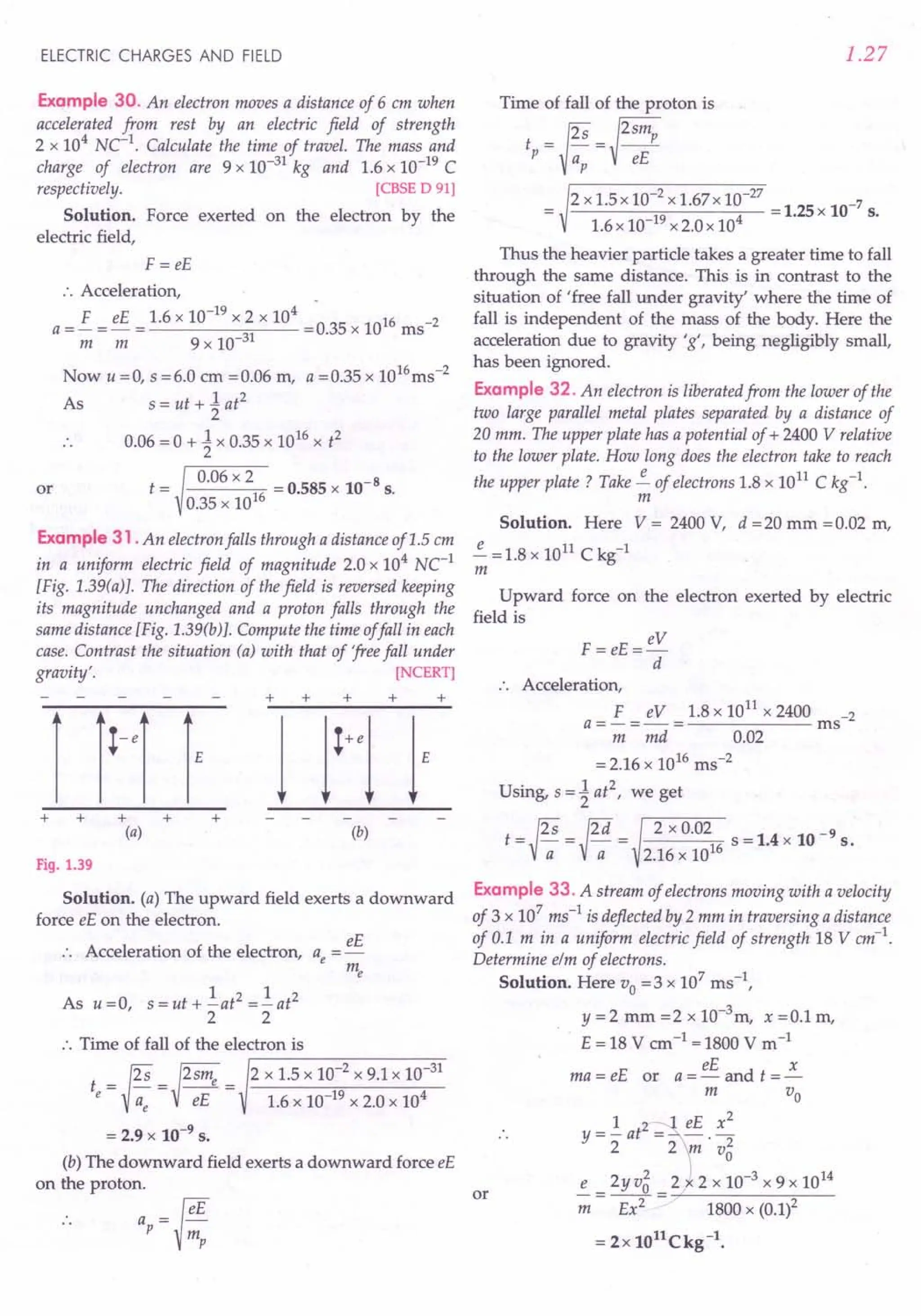
![1.28
Example 34. An electricfield E is set up between the two
parallel plates of a capacitor, as shown in Fig. 1.40. An
electron enters the field symmetrically between the plates
with a speed vo' TIle length of eachplate is I. Find the angle of
deviation of the path of the electron as it comes out of thefield.
~
•
i~.~v-o--+--+----~~-~------------
'1
Fig. 1.40
Solution. Acceleration of the electron in the
upward direction,
eE
a=-
m
Time taken to cross the field, t = J.-
Vo
Upward component of electron velocity on
emerging from field region,
eEl
v =at=--
y mvo
Horizontal component remains same, Vx = Vo
If e is the angle of deviation of the path of the
electron, then
tan e = Vy = eE; or
Vx mvo
e -1 eEl
=tan --2'
mvo
Example 35. A charged particle, of charge 21lC and mass
10 milligram, moving with a velocity of 1000 mls entres a
uniform electric field of strength 103
Ne1
directed
perpendicular to its direction of motion. Find the velocity
and displacement, of the particle after 10 s.
[CBSE Sample Paper 11]
Solution. The velocity of the particle, normal to the
direction of field.
~O ms -I, is constant
The velocity of the particle, along the direction of
field, after 10 s, is given by
"v = "v + ayt
-0 qEy _2x10-6x103x10 -2000 -1
- +-t- 6 - ms
m lOx 10-
The net velocity after 10 s,
v=~v;+v: =~(1000l+(2000l =1000.J5ms-1
Displacement, along the x-axis, after 10 s,
x = 1000x 10m = 10000 m
PHYSICS-XII
Displacement along y-axis (in the direction of field)
after 10 s,
1 1qE 2 1 2 x10-6x 103 2
y=ut+-at2=(O)t+-_Yt =-x -6 x(lO)
!f 2!f 2 m 2 10x10
=10000 m
Net displacement,
r = ~ x2 + y2 = ~(10000)2 + (10000)2 = lOOOO.Jim.
~rOblems For Practice
1. If an oil drop of weight 3.2 x 10⁻¹³
N is balanced in
an electric field of 5 x 10⁵ Vm -I, find the charge on
the oil drop. [eBSE D 93] (Ans. 0.64 x 10⁻¹⁸ C)
2. Calculate the magnitude of the electric field, which
can just balance a deutron of mass 3.2 x 10⁻²⁷kg.
Take g = 10 ms-2. [Punjab 99]
(Ans. 2.0 x 10⁻⁷
Ne1
)
3. A charged oil drop remains stationary when
situated between two parallel plates 20 mm apart
and a p.d. of 500 V is applied to the plates. Find the
charge on the drop if it has a mass of 2 x 10⁻⁴ kg.
Take g = 10 ms-2. (Ans. 8 x 10-13
C)
4. In Millikan's experiment, an oil drop of radius
10-4 em remains suspended between the plates
which are 1 em apart. If the drop has charge of 5e
over it, calculate the potential difference between
the plates. The density of oil may be taken as
1.5gem -3. (Ans. 770 V)
5. A proton falls down through a distance of 2 cm in a
uniform electric field of magnitude 3.34 x 10³NC-1.
Determine (i) the acceleration of the electron (ii) the
time taken by the proton to fall through the
distance of 2 cm, and (iii) the direction of the electric
field. Mass of a proton is 1.67x10⁻²⁷
kg.
(Ans. 3.2 x 10¹¹
ms-2, 3.54 x 1O-7s,
vertically downwards)
6. A particle of mass 10-3kg and charge 5 IlC is thrown
at a speed of 20 ms -1 a§ainst a uniform electric field
of strength 2 x lOS
NC- . How much distance will it
travel before coming to rest momentarily?
(Ans. 0.2 m)
HINTS
1. Use W = qE.
2. E= mg 3.2 x 10-
27
x10 = 2.0xlO-7 NCl.
e 1.6 x 10⁻¹⁹
3.
V
mg = qE or mg = q -
d
:. q = mgd = 2 x 10-4 x10x20x 10-
3
= 8 xlO-8 C.
V 500](https://image.slidesharecdn.com/slaroraclass12thphysicsbyrockytrickster-250318042948-c8b51a5a/75/SL-ARORA-CLASS-12TH-PHYSICS-BY-ROCKY-TRICKSTER-pdf-29-2048.jpg)
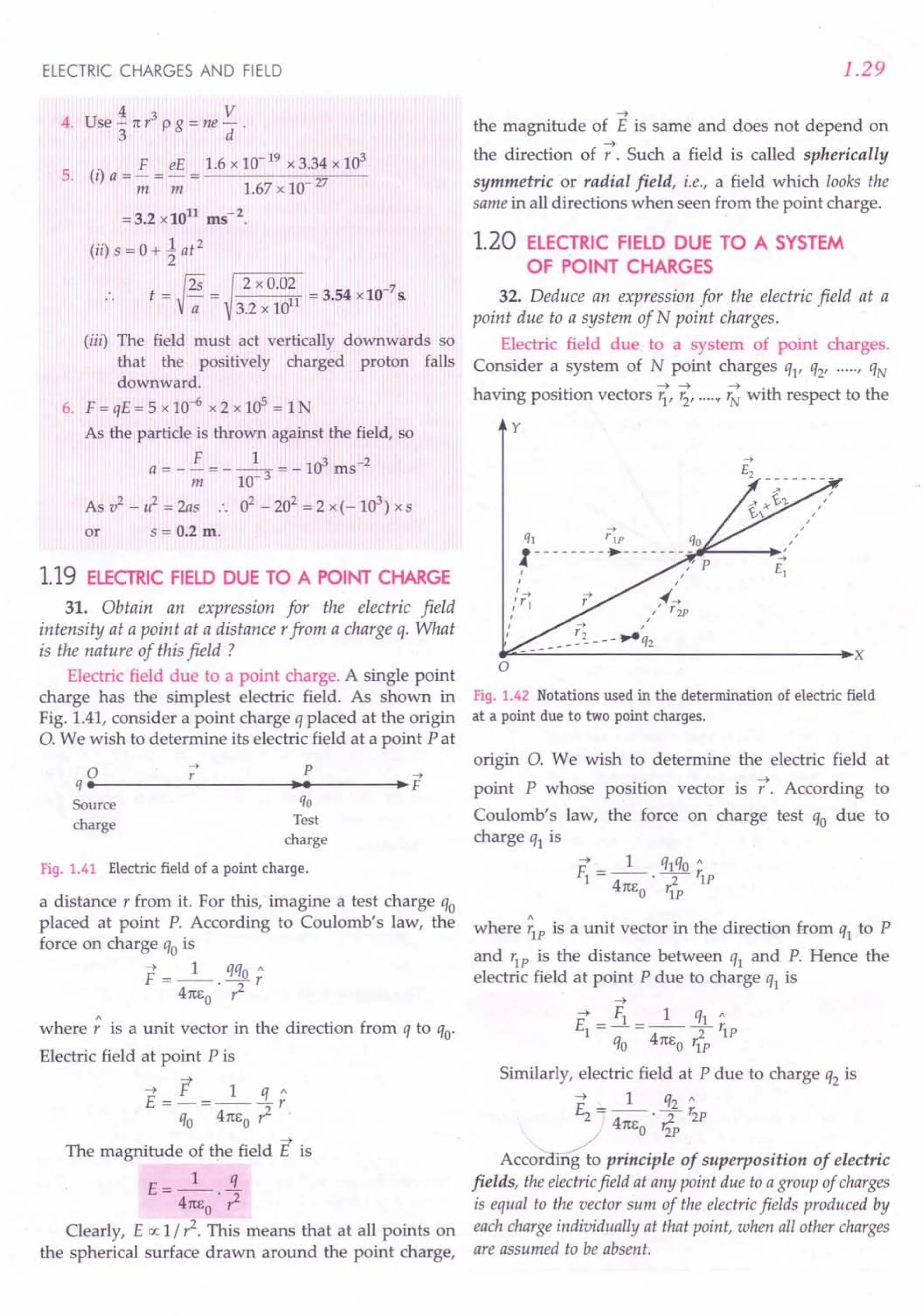
![1.30
Hence, the electric field at point P due to the system
of N charges is
or
--+
£
0- - - - - - - - ~- - - - - - - - - -'),~:~---.,
q --+ ' I - £--+
I rIP , P: I
,_--+
: ~!_4P
I
I
~ r'3P
I
I
I
I
oq3
cY
q,
Fig. 1.43 Electric field at a point due to a system of
charges is the vector sum of the electric
fields at the point due to individual charges.
In terms of position vectors, we can write
N
~ ~
~ 1 qj r - r.
E= -- L ---'
41t1;0 ~ ~2 ~ ~
j= 1
I r - 'i I I r - 'i I
~ 1 N
qj ~ ~
or E= -- L (r - 'i)'
41t1;0 ~
_ ~13
j = 1
Ir
Examples based on
: Electric Fields of Point Charges
Formulae Used
1. E=_l_. ~
41t EO r
2. By the principle of superposition, electric field
due to a number of point charges,
~ ~ ~ -+
E=f1+f2+f3+ ...
Units Used
When q is in coulomb and r in metre; E is in NC-1
or Vm-1
.
PHYSICS-XII
Example 36. Assuming that the charge on an atom is
distributed uniformly in a sphere of radius 10-10
m, what
will be the electric field at the surface of the gold atom ? For
gold, Z =79.
Solution. The charge may be assumed to be con-
centrated at the centre of the sphere of radius 10-10 m.
r = 10-10 m, q = Ze =79 x 1.6 x 1O-19C
1 q 9 x 109 x 79 x 1.6 x 10-19
E = -- - = ----.,..".-;~--
41t EO . ,z (10-10)2
= 1.138 x 10¹³ NC-1•
Example 37. Two point charges of 2.0x 10⁻⁷
C and
1.0 x 10⁻⁷
Care 1.0 em apart. What is the magnitude of the
field produced by either charge at the site of the other ? Use
standard value of1 / 41t EO' [Punjab 98]
Solution. Here q1 =2.0 x 10⁻⁷
C
q2 = 1.0 x 10⁻⁷ C r = 1.0 em = 0.01 m
Electric field due to q1 at the site of q2'
E = _1_ q1 = 9 x 10
9
x 2.0 x 10-
7
1 41tE
O
',z (0.10)2
= 1.8 x 10⁷ NC-1.
Electric field due to q2 at the site of q1'
E = _1_ q2 = 9 x 10
9
x 1.0 x 10-
7
2 41tE
O
',z (0.10)2
= 9x 10⁶ NC-1.
Example 38. Two point charges of +5xlO-19
C and
+ 20 x 10-19
C are separated by a distance of 2 m. Find the
point on the line joining them at which electric field
intensity is zero. [CBSE OD OlC)
Solution.
-N -N
ql = + 5 x 10 C q2 = + 20 x 10 C
• •••• •
A £2 P £1 B
14---- x ----+l~11+-4
---- 2 - x ~I
Fig. 1.44
The electric field at point P will be zero if
El = Ez
1 5 x 10-19 1 20 x 10-19
41t1;0 x2 4m:
o
' (2 - x)2
or 4x2 = (2 _x)2 or 2x =± (2 -x)
or x = 2 /3 m or - 2 m
At x = - 2 m i.e., at 2 m left of ql' electric fields due
to both charges will be in same direction. So x = - 2 m
is not a possible solution.
Hence electric field will be zero at 2 /3 m to the
right of ql'](https://image.slidesharecdn.com/slaroraclass12thphysicsbyrockytrickster-250318042948-c8b51a5a/75/SL-ARORA-CLASS-12TH-PHYSICS-BY-ROCKY-TRICKSTER-pdf-31-2048.jpg)
![ELECTRIC CHARGES AND FIELD
Example 39. Two point charges of + 16 IlC and - 9 IlC are
placed 8 em apart in air. Determine the position of the point
at which the resultant field is zero. [Punjab 94]
Solution. Let P be the point at distance x ern from
A, where the net field is zero.
q1 = + 16~C q2 = - 9 ~C
• • •
A P B
"14--- X
---~~14t__-- 8- x ~I
Fig. 1.45
or
At point P, EI + E2= 0
kx16x10-6
+ kx(-9)x10-6
= 0
(xx 10-2)2 [(8-x)x10-2]2
16 9
x2 (8 - x)2
4 3
-=+--
X - 8-x
32
x=-cm,32 ern
7
or
or
At x = 32 em, both EI and E2 will be in the same
7
direction, therefore, net electric field cannot be zero.
Hence x = 32 em
i.e., electric field is zero at a point 24 em to the right of
- 9 IlC charge.
Example 40. Two point charges qI = + 0.2 C and
q2 = + 0.4 C are placed 0.1 m apart. Calculate the electric
field at
(a) the midpoint between the charges.
(b) a point on the line joining qI and q2 such that it is
0.05 m away from q2 and 0.15 m away from qI'
[CBSE D 93C]
Solution. (a) Let 0 be the midpoint between the
two charges.
ql =+ 0.2 C
• •
q2 =+ 0.4 C
•
o
£1 -----.~ £2
••
14------0.1 m ------ ..••
~I
A B
Fig. 1.46
Electric field at 0 due to qI'
. E = kqI = 9 x 10
9
x 0.2 =7.2 x 10¹¹ NCI,
1 r
I
2 (0.05)2
acting along AO
1.31
Electric field at 0 due to q2'
E = kq2 = 9 x 10
9
x 0.4
2 ri (0.05)2
= 14.4 x 10¹¹ NCI, acting along BO
Net field at 0 = ~ - EI
= 7.2 x 10¹¹ NC1, acting along BO.
(b) Electric field at P due to qI'
kqI 9 x 109 x 0.2 .
EI = ~ = 2' acting along AP
'1 (0.15)
Electric field at P due to q2'
kq2 9 x 109 x 0.4 .
E2= ~ = 2' actmg along BP
'i (0.05)
q1 =+ 0.2 C q2 = + 0.4 C £1 -----.
• • .p
A B £2 -----.
14 0.1 m ~14 0.05 m---+t
Fig. 1.47
Net electric field at point P is
E= E + E =9X10⁹[~+~]
1 2 (0.15)2 (0.05)2
= 1.52 x 10¹² NC1
, acting along AP.
Examfle 41. Two point charges qI and q2of10 -8 Cand
-10 - C respectively are placed 0.1 m apart. Calculate the
electric fields at points A, Band C shown in Fig. 1.48.
-+ [NCERT]
£1
B +1O-8C A
....--_________ _1O-8
C
1+-- 0.05m -H4- 0.05m ..•••.. 0.05m -~
Fig. 1.48
~
Solution. The electric field vector EI at A due to the
positive charge qI points towards the right and it has a
magnitude,
E = kqI = 9 x 10
9
x 10-
8
NC-I
1 r? (0.05)2
=3.6 x 10⁴
NCI](https://image.slidesharecdn.com/slaroraclass12thphysicsbyrockytrickster-250318042948-c8b51a5a/75/SL-ARORA-CLASS-12TH-PHYSICS-BY-ROCKY-TRICKSTER-pdf-32-2048.jpg)
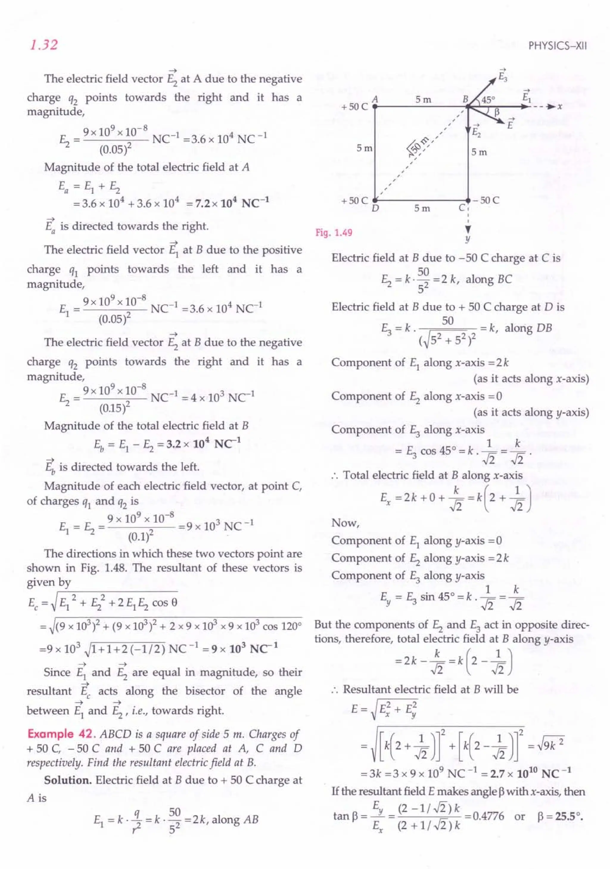
![ELECTRIC CHARGES AND FIELD
Example 43. Four charges + q, + q, - q, - q are placed
respectively at thefour corners A, B, C and D of a square of
side 'a'. Calculate the electricfield at the centre of the square.
[Punjab 96C]
Solution. Let EA, E8' 11: and EDbe the electric fields
at the centre °of the square due to the charges at A, B,
C and D respectively. Their directions are as shown in
Fig. I.50(a).
+q a +q
A~-----~B
+q a +q
A------ ..•
B
D~-----~C D¥--- ..••....
--..,.C
-q -q -q -q
(a) (b)
Fig. 1.50
Since all the charges are of equal magnitude and at
the same distance r from the centre 0, so
EA = EB= 11: = ED = k· ~ = ( a
q
)2 = 2 ~~
..fi [.: ? + ? = a2]
Because EA and 11: act in the same direction, so
their resultant is
E _ E P _ 2kq 2kq _ 4kq
1 - A + L - a2 + a2 - a2
Similarly, resultant of EBand ED is
4kq
Ez = EB+ ED =-2
a
Now, the resultant of EI and E2 will be
E = ~ EI 2 + E22= (:~q r+ ( 4a~q
r
= 4..fi k!L
a2 '
directed parallel to AD or BC, as shown in Fig. 1.50(b).
E 1
cos~=--1=- .. ~=45°
E ..fi
i.e.,the resultant field is inclined at an angle of 45°with AC.
Example 44. Two point charges +6q and -8q are placed at
the vertices' B' and 'C' of an equilateral triangle ABC of side
'a' as shown in Fig. 1.51(a). Obtain the expression for (i) the
magnitude and (ii) the direction of the resultant electricfield
at the vertex A due to these two charges. [CBSE OD 14C]
Solution. (i) As shown in Fig. 1.5I(b), the fields at
~ -+
point A due to the charges at Band Care EBA and EAC
respectively.
1.33
A
+6q '--------->- 8q + 6q__ ----- ...•- 8q
B C B a C
Fig. 1.51 (a) ( b)
Their magnitudes are
1 6q 1 q
EBA =--'2=6E,where E=--'2
4n~a 4n~a
1 8q
EAC =--'2=8E
4m,o a
The magnitude of the resultant field is
Enet = ~ E~A + E~c +2 EBAEACcosI20°
= (6 E)2 + (8 E)2 + 2 x 6 E x 8 E x ( -~ )
= E.J52 = _1_ q.J52
4m,o a2
(il) If the resultant field makes an angle ~with AC, then
EBAsinI20° 6Ex(.J3/2) 3.J3
tanf = ------"'''--------
EAC + EBAcosI20° 8E+6E( _~) S-
.. ~ = tan-
l
( 3:J
<prOblems For Practice
1. An electron is separated from the proton through a
distance of 0.53 A. Calculate the electric field at the
location of the electron. (Ans. 5.1 x 10¹¹NC-l)
2. Determine the electric field produced by a helium
nucleus at a distance of 1 A from it.
(Ans. 2.88 x 10¹¹NCI)
3. Two point charges + q and + 4q are separated by a
distance of 6a. Find the point on the line joining the
two charges where the electric field is zero.
(Ans. At a distance 2a from charge + q)
4. Two point charges ql and q2 of 2 x 1O-8C and
- 2 x 1O-8C respectively are placed 0.4 m apart.
Calculate the electric field at the centre of the line
joining the two charges. [. 'l5E F 94C)
(Ans. 900 NC-l
, towards the -" charge)](https://image.slidesharecdn.com/slaroraclass12thphysicsbyrockytrickster-250318042948-c8b51a5a/75/SL-ARORA-CLASS-12TH-PHYSICS-BY-ROCKY-TRICKSTER-pdf-34-2048.jpg)
![1.34
5. Two point charges + q and - 2q are placed at the
vertices 'B' and'C' of an equilateral triangle ABC
of side 'Ii as given in the figure. Obtain the
expression for (i) the magnitude and (ii) the
direction of the resultant electric field at the vertex
A due to these two charges. [CBSE 00 14C]
[Ans. (i) _1_ q.J3 (ii) 30° with Aq
41tEo a2
A
Fig. 1.52
6. Find the magnitude and direction of electric field at
point P in Fig. 1.53.
A
+q
E .
B
p
a
*---------------~+q
C
a
Fig. 1.53
(
Ans. E= _1_ 2~, along BP producedJ
41tEo a
7. Three charges, each equal to q are placed at the three
corners of a square of side a. Find the electric field
at the fourth corner. (Ans. (2..fi + 1) q 2J
81t eo a
8. Figure 1.54 shows four point charges at the corners
of a square of side 2 cm. Find the magnitude and
direction of the electric field at the centre 0 of the
square, if Q = 0.02 Jlc.
-2Q 2cm +2Q
A , B
,
, ,
, ,
,, ,
, ,
, ,
, ,
A
/,'0'"
, ,
, ,
, ,
, ,
, ,
, ,
D ' , c
+Q 2em -Q
_1_ = 9 x 10⁹ Nm2 C-2.
41tEo
2em
2cm
Fig. 1.54
Use [ISCE 98]
(Ans. s-Ii x105
Nc1
, parallel to BA)
PHYSICS-XII
HINTS
1. Electric field at the location of the electron,
_ 1 q _ 9 x 109
x 1.6 x 10-19
_ 11 C-1
E ---. -2 - 102 - 5.1 xlO N .
41tEo r (0.53 x 10- )
2. Here q = + 2e and r = 1A = 10-10
m.
3. Suppose the electric field is zero at distance x from
the charge + q. Then
1 q 1 4q
41t EO . x2 = 41t EO . (6a - x)2
or (6a-x)2=4x2 or 6a-x=2x
or x = 2a
.. Electric field is zero at distance 2a from the
charge + q.
4. Proceed as in Q. 1.8 on page 1.81.
5. Proceed as in the solution of Example 44 on
page 1.33.
6. Here EA and Ec are equal and opposite and hence
cancel out.
BP = a sin 45° = a / ..fi
Hence E= E = _1_ q
B 41tEo· (a / ..fi)2
__ 1_ 2q along BP produced.
- 41tEo . a2 '
7. Refer to Fig. 1.55.
A
EVe EB
o E
a
q , A
,
,
,
,
~~,/
,
,
,
,
a
a
qB• -------a------ ...•
C q
Fig. 1.55
ED = ~ E~ + E2 + EB
(
q J2 + ( q J2 + q
41t EO a2 41t EO a2 41t Eo (..fi a)2
= .s:[v';+ -4]=(2..fi + 1) -q-2 .
41t Eo a 2a 81t Eo a
8. Here, AB = BC = CD = AD = 2 em
~22 + 22
AO = BO = CO = DO = = ..fi em
2
=..fi x 10-2 m](https://image.slidesharecdn.com/slaroraclass12thphysicsbyrockytrickster-250318042948-c8b51a5a/75/SL-ARORA-CLASS-12TH-PHYSICS-BY-ROCKY-TRICKSTER-pdf-35-2048.jpg)
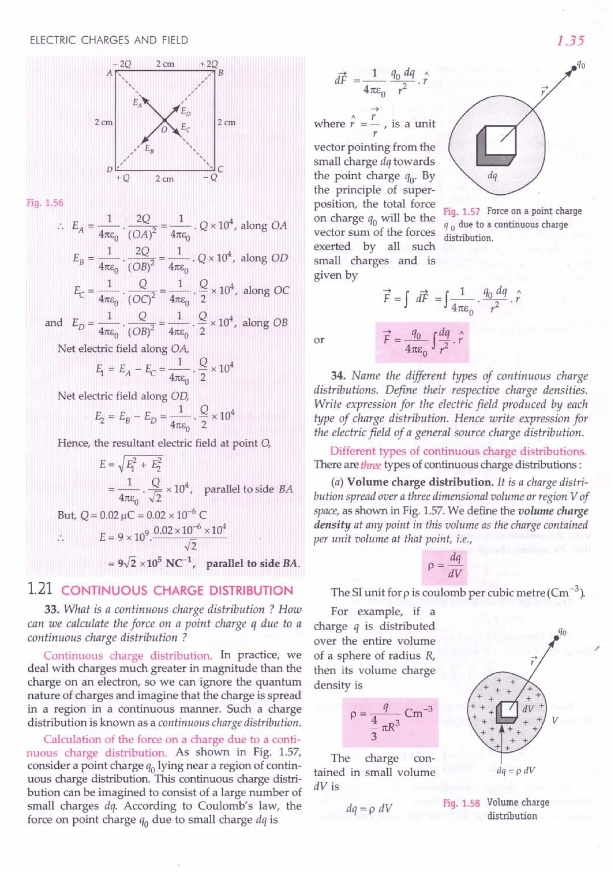
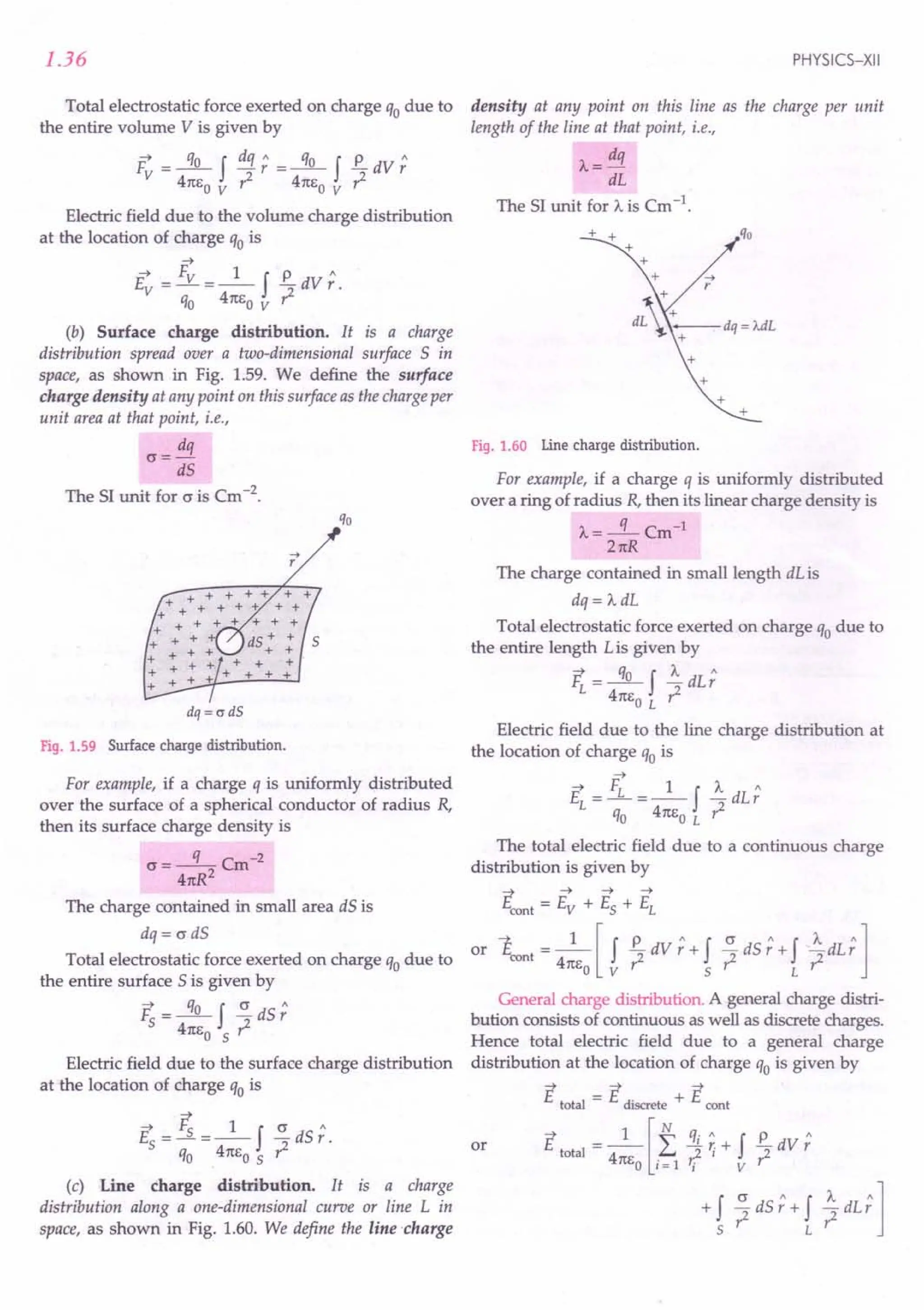
![ELECTRIC CHARGES AND FIELD
" ~
In all the above cases, r = r / r is a variable unit
vector directed from each point of the volume, surface
or line charge distribution towards the location of the
point charge qo'
Formulae Used
1. Volume charge density, p = ~
dV
2. Surface charge density, c = ~~
3. Linear charge density, A. = ~~
4. Force exerted on a charge qo due to a continuous
charge distribution,
F = -'l!L f dq r
4m: r2
o
5. Electric field due to a continuous charge distribution,
E=_l_fdq r
4m:a r2
Units Used
p is in Cm -3, o in Cm -2, A.in Cm-1 and E in NC-1
.
Example 45. A charged spherical conductor has a surface
density of 0.7 Cm-2
. When its charge is increased by 0.44 C,
the charge density changes by 0.14 Cm-2
. Find the radius of
the sphere and initial charge on it.
Solution. c = q 2
41tr
In first case: O.7=-q-
41tl
or
In second case :
0.7 + 0.14 = q + 0;
41t
0.84 = q + 0.44
41tr2
Dividing (ii) by (i), we get,
0.84 q +0.44
or
0.7 q
~ =1+ 0.44
5 q
.. Initial charge, q = 2.2 C.
From (i), r=~crxq41t =~0.72~41t
2.2 x 7
1---- =O.Sm.
0.7x 4 x 22
1.37
Example 46. Sixty four drops of radius 0.02 m and each
carrying a charge of 5 !lC are combined to form a bigger
drop. Find how the surface density of electrification will
change if no charge is lost.
Solution. Volume of each small drop
=i 1t(0.02)3 m 3
3
Volume of 64 small drops = i 1t(0.02)3 x 64 m 3
3
Let R be the radius of the bigger drop formed. Then
i 1tR3 = i 1t(0.02)3 x 64
3 3
or R3 = (0.02)3 x 43
. . R = 0.02 x 4 = 0.08 m
Charge on small drop = 5!lC = 5 x 10⁻⁶
C
Surface charge density of small drop,
c = _q_ = 5 x 10⁻⁶ Cm-2
1 41tl 41t(0.02)2
Surface charge density of bigger drop,
5 x 10-6
x 64 C -2
cr= m
2 41t(0.08)2
cr1 = 5 x 10-6 X 41t(0.08)2 = != 1 : 4.
cr2 41t(0.02)2 5 x 10 6 x 64 4
...(i)
Example 47. Obtain theformula for the electricfield due to
a long thin wire of uniform linear charge density A. without
using Gauss's law. [NCERT 1.30]
Solution. Electric field of a line charge from
Coulomb's law. Consider an infinite line of charge with
uniform line charge density ;>..,. as shown in Fig. 1.61.
We wish to calculate its electric field at any point P at a
distance y from it. The charge on small element dx of
the line charge will be
dq = A.dx
...(ii)
Fig. 1.61 A section of an infinite line of charge.](https://image.slidesharecdn.com/slaroraclass12thphysicsbyrockytrickster-250318042948-c8b51a5a/75/SL-ARORA-CLASS-12TH-PHYSICS-BY-ROCKY-TRICKSTER-pdf-38-2048.jpg)
![1.38
The electric field at the point P due to the charge
element dq will be
dE=_l_ dq =_1_ ~
4m,0 .?- 4n60
' y2 + x2
The field dE has two components:
dEx = - dE sin e and dEy = dE cos e
The negative sign in x-component indicates that
-+
d Ex acts in the negative x-direction. Every charge ele-
ment on the right has a corresponding charge element
on the left. The x-components of two such charge
elements will be equal and opposite and hence cancel
-+
out. The resultant field E gets contributions only from
y -components and is given by
X=+OO
E = Ey = fdEy = fcos e dE
x=-oo
xf=OO 1 J... dx
=2 cose.--. 2 2
x =0 4n60 y + x
x=oo
J... f dx
=-- cose---
2 n60 x = 0 y2 + x2
Now x = y tan e
dx = y sec2e de
J... 6 = 1t /2 sec2 e de
E = -- f cos o ~y-----;:;---
2n60 6=0 y2(1+tan2e)
J... 6= 1t/2 J...
=-- f cos e de =-- [sine]~/2
2n60 y 6=0 2n60 y
or
J... (. n . 0)
= 2 n6
0
y sm 2" - sm
E=_J..._.
2n60
y
Example 48. A charge is distributed uniformly over a ring or
of radius 'a'. Obtain an expression for the electric intensity E
at a point on the axis of the ring. Hence show that for points
at large distances from the ring, it behaves like a point
charge. [CBSE Sample Paper 90]
Solution. Suppose that the ring is placed with its
plane perpendicular to the x-axis, as shown in Fig 1.62.
Consider a small element dl of the ring.
As the total charge q is uniformly distributed, the
charge dq on the element dl is
dq=-q-.dl
2na
PHYSICS-XII
dl
dl
Fig. 1.62
-+
:. The magnitude of the field dE produced by the
element dl at the field point P is
aE = k . dq = kq . dl
r2 2na r2
-+
As shown in Fig. 1.62, the field dE has two
components:
1. the axial component dE cos e, and
2. the perpendicular component dE sin e.
Since the perpendicular components of any two
diametrically opposite elements are equal and
opposite, they all cancel out in pairs. Only the axial
components will add up to produce the resultant field
E at point P, which is given by
2M
E = f dEcos e
o [.: Only the axial components
contribute towards E]
2M k k 2M
= f -q . dl . .:. = qx. ~ f dl
o 2na ?- r 2na r 0
[.: cos B =;]
E= kqx =_1_ qx
(x2 + a2)3/2 41tEo' (x2 + a2)3/2 •
Special case
For points at large distances from the ring, x » a
E _ kq _ 1 q
- x2 - 4n6 . x2
o
This is the same as the field due to a point charge,
indicating that for far off axial points, the charged ring
behaves as a point charge.
Example 49. A thin semicircular ring of radius a is
charged uniformly and the charge per unit length is J.... Find
the electric field at its centre. [CBSE PMT 2000, AIEEE 2010]](https://image.slidesharecdn.com/slaroraclass12thphysicsbyrockytrickster-250318042948-c8b51a5a/75/SL-ARORA-CLASS-12TH-PHYSICS-BY-ROCKY-TRICKSTER-pdf-39-2048.jpg)
![ELECTRIC CHARGES AND FIELD
Solution. Consider two symmetric elements each
of length dl at A and B. The electric fields of the two
elements perpendicular to PO get cancelled while
those along PO get added.
Electric field at 0 due to an element of length dl is
1 dq
dE = ---cosS [Along PO]
41tEo a2
1 Adl
=----cosS
4m,0 a2
[dl = adS]
Fig. 1.63
Total electric field at the centre 0 is
1(/2 1(/2 SdS
E = f dE =2 f _1_Acos
-1(/2 0 41tl:o a
= _1_~[SinS]~/2 =_1_~.1 =_"_.
2 1tl:o a 2 1tl:o a 21tEoa
rproblems for Practice
1. A uniformly charged sphere carries a total charge
of 21tx 1O-12C.Its radius is 5 em and is placed in
vacuum. Determine its surface charge density.
(Ans. 2 x 10⁻¹⁰Cm -2)
2. What charge would be required to electrify a
sphere of radius 15 em so as to get a surface charge
density of 2. " Cm -2 ?
11 r- (Ans, 1.8 x 10⁻⁷ C)
3. A metal cube of length 0.1 m is charged by 12~C.
Calculate its surface charge density.
(Ans, 2 x 10⁻⁴ Cm -2)
4. Two equal spheres of water having equal and
similar charges coalesce to form a large sphere. If
no charge is lost, how will the surface densities of
electrification change? (Ans. 0"1
: 0"2= 22/3 : 2)
1.39
HINTS
1. Use O"=~.
41tr
2. Use q = 41tr
2
0".
3. Surface area of cube = 6 x /2 = 6 x 0.01 = 0.06 m2.
4 .i 1tR3 = 2 x .i 1tr3 or R = 21/3 r
. 3 3
2
2 - 2
0"1_ q 41t R _ R
2
_ 23 r _ 2/3.
---- --------2 2
0"2 41t?' 2q 2r2 2 r2 .
1.22 ELECTRIC DIPOLE
35. What is an electric dipole ? Define dipole moment
and give its SI unit. Give some examples of electric
dipoles. What are ideal or point dipoles ?
Electric dipole. A pair of equal and opposite charges
separated by a small distance is called an electric dipole.
Dipole moment. It measures the strength of an
electric dipole. The dipole moment of an electric dipole is a
vector whose magnitude is either charge times the separation
between the two opposite charges and the direction is along
the dipole axis from the negative to the positive charge.
As shown in Fig. 1.64, consider an electric dipole
consisting of charges + q and - q and separated by dis-
tance 2 a. The line joining the charges is called dipole axis.
-q
•
+q
•••
..•
p
Fig. 1.64
Dipole moment = Either charge x a vector drawn
from negative to positive charge
or
~ ~
p=qx2a
~
Thus the dipole moment p is a vector quantity. Its
direction is along the dipole axis from - q to + q and its
magnitude is
p= qx2a
The SI unit of dipole moment is coulomb metre (Cm).
When both the charge q and separation 2 a are finite, the
dipole has a finite size (equal to 2 a), a location
(midpoint between + q and - q), a direction and a
strength.
Examples of electric dipoles. Dipoles are common
in nature. In molecules like Hz0' HCI, C2HSOli
C~COOli etc., the centre of positive charges does not
fall exactly over the centre of negative charges. Such
molecules are electric dipoles. They have a permanent
dipole moment.](https://image.slidesharecdn.com/slaroraclass12thphysicsbyrockytrickster-250318042948-c8b51a5a/75/SL-ARORA-CLASS-12TH-PHYSICS-BY-ROCKY-TRICKSTER-pdf-40-2048.jpg)
![1.40
Ideal or point dipole. We can think of a dipole in
which size 2a ~ 0 and charge q ~ 00 in such a way that
the dipole moment, p = q x 2 a has a finite value. Such a
dipole of negligibly small size is called an ideal or point
dipole.
Dipoles associated with individual atoms or molecules
may be treated as ideal dipoles. An ideal dipole is
specified only by its location and a dipole moment, as
it has no finite size.
1.23 DIPOLE FIELD
36. What is a dipole field? Why does the dipole field at
large distance falls off faster than 1/r2 ?
Dipole field. The electric field produced by an electric or
dipole is called a dipole field. This can be determined by
using (a) the formula for the field of a point charge and
(b) the principle of superposition.
Variation of dipole field with distance. The total
charge of an electric dipole is zero. But the electric field
of an electric dipole is not zero. This is because the
charges + q and - q are separated by some distance, so
the electric fields due to them when added do not
exactly cancel out. However, at distances much larger
than the dipole size (r»2a), the fields of + q and-q
nearly cancel out. Hence we expect a dipole field to fall
off, at larger distance, faster than 1/,1, typical of the
field due to a single charge. In fact a dipole field at
larger distances falls off as 1/ ?
1.24 ELECTRIC FIELD AT AN AXIAL POINT
OF A DIPOLE
37. Derive an expression for the electric field at any
point on the axial line of an electric dipole.
Electric field at an axial point of an electric dipole.
As shown in Fig. 1.65, consider an electric dipole
consisting of charges + q and - q, separated by distance
2a and placed in vacuum. Let P be a point on the axial
line at distance r from the centre 0 of the dipole on the
side of the charge + q.
p
-0 +q s., P E+q
••
---+1-- • ---
.....•
_--+_--_•.
-q
14--- 2a ---..
14 r----~.I
Fig. 1.65 Electric field at an axial point of dipole.
Electric field due to charge - q at point Pis
~ -q"
E = P (towards left)
-q 4nEo (r + al
where p is a unit vector along the dipole axis from -q
to +q.
PHYSICS-XII
Electric field due to charge + q at point Pis
E = q p (towards right)
+q 4nEo (r - al
Hence the resultant electric field at point P is
~ -;:; ~
E axial = 1:, +q + E _q
= 4:EJ(r~a)2 - (r: a)2] P
q 4ar"
= 4nEO . (,1 - a2)2 p
~ 1 2pr"
Eaxial = 4nEo . (,1 _ a2)2 p
Here p = q x 2 a = dipole moment.
For r» a, a2
can be neglected compared to?
~ 1 2p"
Eaxial - -- - p
- 4nEo . r3
(towards right)
Clearly, electric field at any axial point of the dipole
acts along the dipole axis from negative to positive
~
charge i.e., in the direction of dipole moment p .
1.25· ELECTRIC FIELD AT AN EQUATORIAL
POINT OF A DIPOLE
38. Derive an expression for the electric field at any
point on the equatorial line of an electric dipole.
Electric field at an equatorial point of a dipole. As
shown in Fig. 1.66, consider an electric dipole consis-
ting of charges - q and + q, separated by distance 2a
and placed in vacuum. Let P be a point on the equa-
torialline of the dipole at distance r from it.
i.e., OP = r
_q __ ~ __ a
__ ~o~_a__ ~.+q
A ----+ B
P
Fig. 1.66 Electric field at an equatorial point of a dipole.](https://image.slidesharecdn.com/slaroraclass12thphysicsbyrockytrickster-250318042948-c8b51a5a/75/SL-ARORA-CLASS-12TH-PHYSICS-BY-ROCKY-TRICKSTER-pdf-41-2048.jpg)
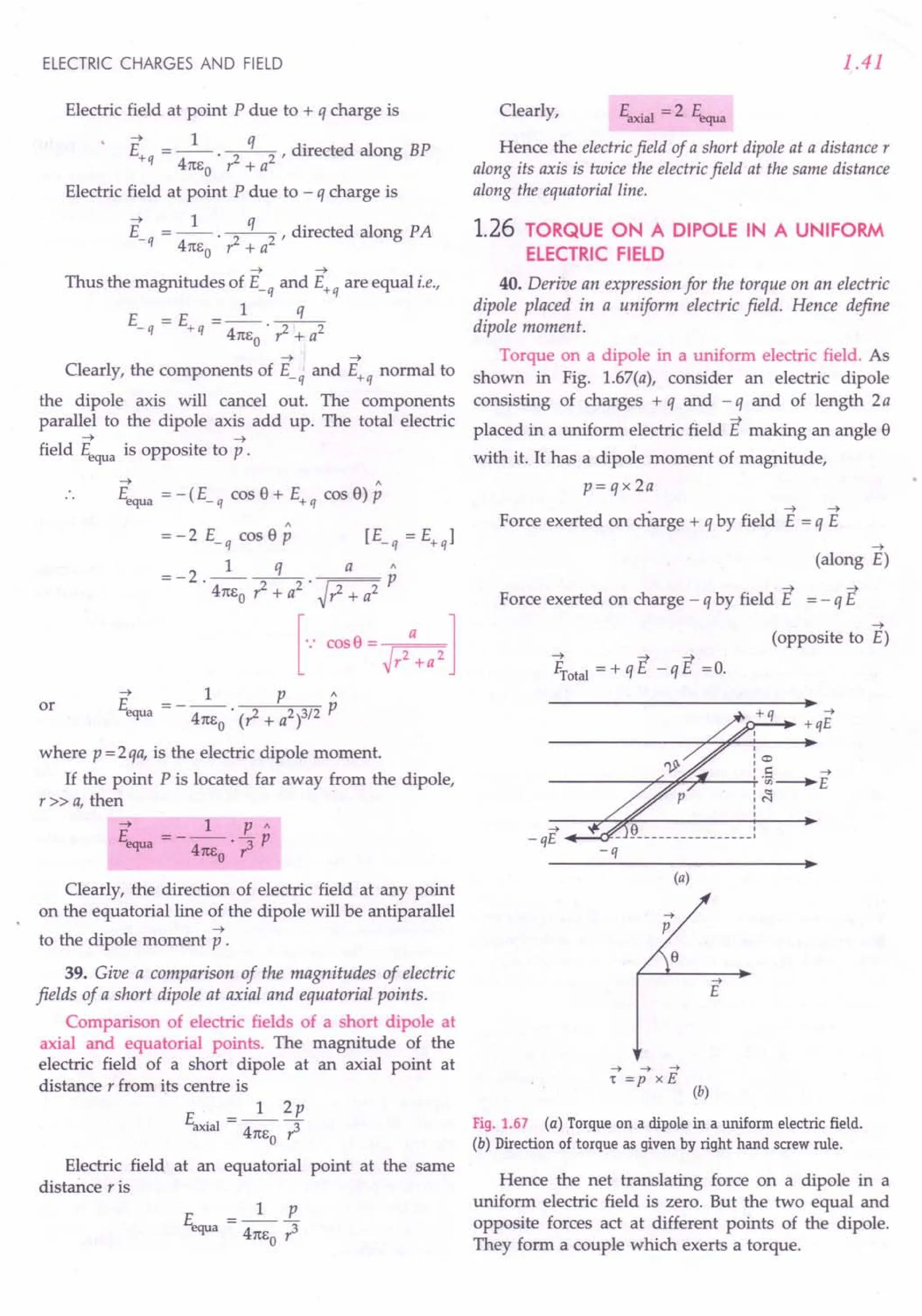
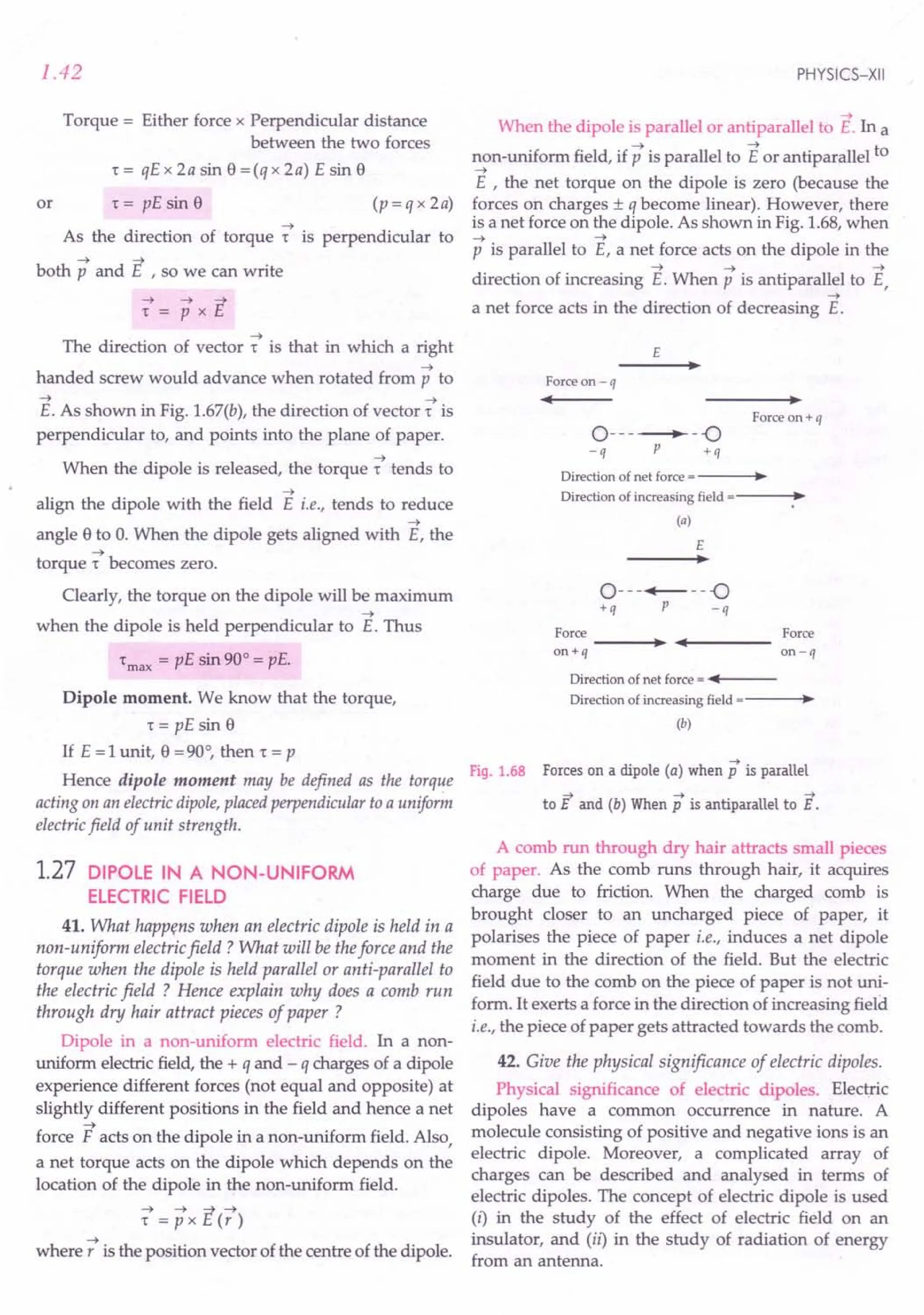
![ELECTRIC CHARGES AND FIELD
For Your Knowledge
~ In a uniform electric field, an electric dipole expe-
riences no net force but a non zero torque.
~ As the net forceon a dipole in a uniform electricfield
is zero, therefore, no linear acceleration is produced.
~ 'Torque on a dipole becomes zero when it aligns itself
parallel to the field.
~ Torque on a dipole is maximum when it is held
....
perpendicular to the field E .
~ In a non-uniform electricfield, a dipole experiences a
non zero forceand non zero torque. In the specialcase
when the dipole moment is parallel or antiparallel to
the field, the dipole experiences a zero torque and a
non zero force.
•
-- A non-uniform or A B C
-- • •
specifically an
increasing E-field •
may be represen-
• Directionof
ted by field lines
as shown. Fig.1.69
increasing
E-field
Clearly, EA < EB < Ec
~ The direction ofthe electricfield at an axialpoint ofan
electric dipole is same as that of its dipole moment
and at an equatorial point it is opposite to that of
dipole moment.
~ The strength ofelectricfield at an axialpoint of a short
dipole is twice the strength at the same distance on
the equatorial line.
~ At larger distances, the dipole field (E ex: 1/ r3
)
decreases more rapidly than the electric field of a
point charge (E ex: 1/ r2
).
Formulae Used
1. Dipole moment, p = q x 2a; where 2a is the
distance between the two charges.
2. Dipole field at an axial point at distance r from the
centre of the dipole is
E . =_1_ 2pr
axial 41t EO . (r2 _ a2)2
When r » a, E __ 1_ 2p
axial - 41t E . r3
o
3. Dipole field at an equatorial point at distance r
from the centre of the dipole is
1 p
~a = 41tEo . (? + a2)3/2
When r» a, F. __ 1_ L
"'JUa - 41t E . r3
o
4. Torque, 't = pE sin 9,where 9is the angle between
.... ....
p and E.
1.43
Units Used
Charge q IS m coulomb, distance 2a in metre,
dipole moment p in coulomb metre (Cm), field E
in NC-l
or Vm-l
.
Example 50. Two charges, one + 5 J.1C
and another - 5 J.1C
are placed 1mm apart. Calculate the dipole moment.
[CBSE OD 94C]
Solution. Here q = 5 J.1C
= 5 x 10⁻⁶ C,
2a =1 mm =10-3 m
Dipole moment,
p= qx 2a =5 x 10-6 x 10-3 =5 x 10⁻⁹
Cm.
Example 51. An electric dipole, when held at 30° with
respect to a uniform electric field of104
NC-l
experiences a
torque of 9 x 10-26 Nm Calculate dipole moment of the
dipole. [CBSE D 96]
Solution. Here S·=30°, E=104 NC-l
,
't =9 x 10-26 Nm
As 't = pE sin S
:. Dipole moment,
r 9 x 10-26 9 x 10-26
p---- -
- E sin S - 104 x sin30° - 104 x 0.5
= 1.8 x 10⁻²⁹
Cm.
Example 52. An electric dipole consists of two opposite
charges of magnitude 1/3 x 10-7
C, separated by 2 em. The
dipole is placed in an external field of3 x 107
uc:'. What
maximum torque does the electric field exert on the dipole?
Solution. Here q =.!. x 10-7 C, 2a =2 em =0.02 m,
3
E =3 x 10⁷
NCl
't
max
= pE sin 90° = q x 2a x Ex 1
= .!.x 10-7 x 0.02 x 3 x 107 x 1= 0.02 Nm.
3
Example 53. Calculate the electric field due to an electric
dipole of length 10 em having charges of1 J.1C
at an equatorial
point 12 em from the centre of the dipole.
Solution. Here q =1 J.1C
= 10-6 C, r =12 em =0.12 m,
2a =10 em, a = 5 em =0.05 m
E =_1_ 2qa
equa 41tEo' (1+ a2)3/2
9x 109
x2 x 10-6 x 0.05
(0.122 + 0.052)3/2
9x 100
(0.13)3](https://image.slidesharecdn.com/slaroraclass12thphysicsbyrockytrickster-250318042948-c8b51a5a/75/SL-ARORA-CLASS-12TH-PHYSICS-BY-ROCKY-TRICKSTER-pdf-44-2048.jpg)
![1.44
Example 54. Two point charges, each of5 IlC but opposite
in sign, are placed 4 em apart. Calculate the electric field
intensity at a point distant 4 em from the midpoint on the
axial line of the dipole. [Punjab 02]
Solution. Here q = 5 X 1O-6
C, 2a =0.04 m,
a =0.02 m, r =0.04 m
1 2 (q x 2a) r
411:6
0
(,.z _ a2)2
9 x 109 x 2 x 5 x 10-6 x 0.04 x 0.04
[(0.04)2 -(0.02lf
144 = 108 NC-1.
144 x 10-8
Example 55. Two charges ± 10 IlC are placed 5.00 mm
apart. Determine the electricfield at (a) a point P on the axis
of the dipole 15em away from its centre 0 on the side of the
positive charge, (b) a point Q, 15em away from 0 on a line
passing through 0 and normal to the axis of the dipole.
[NCERT]
Solution. Here q = 10 IlC = 10-5
C
2a = 5 mm = 5 x 10⁻³ m
r = 15 em = 15 x 10-2 m
(a) Field at the axial point P of the dipole is
~ 2p 2xqx2a
E =--
P 411:
60~ 411:
60 r3
9 x 109
x 2 x 10-5
x 5 x 10-3
NC-1
(15 x 10-2)3
= 2.66 x 10⁵ NC-1 , along AS.
This field is directed along the direction of dipole
moment vector, i.e., from -q to +q, as shown in
Fig. 1.70(a).
A 0 B e,
••
---IIf--- ••---------••
---I~~
- 10 IlC + 10 IlC P
(a)
->
j
B
EQ "Q
-> ' '
, '
EA I
" :
, ' ,
, ' ,
, , ,
, , ,
, , ,
, , '
, , '
" I
A" : '.B
- 10 IlC 0 + 10 IlC
(b)
Fig. 1.70
PHYSICS-XII
(b) Field at the equatorial point Q of the dipole is
~ p qx 2a
% = 411:6r3 = 411:
6 r 3
o 0
9 x 109
x 10-5
x 5 x 10-3
Net
(15 x 10-2)3
= 1.33 x 10⁵
NC-1
, along BA .
This field is directed opposite to the direction of the
dipole moment vector, i.e., from + q to -q, as shown in
Fig. 1.70(b).
Example 56. Theforce experienced by a unit charge when
placed at a distance of 0.10 m from the middle of an electric
dipole on its axial line is 0.025 Nand when it is placed at a
distance of 0.2 m, theforce is reduced to 0.002 N. Calculate
the dipole length. .
. 1 2pr
Solution, Ea ial = --',.z 2 2
XI 411:60 ( _ a )
In first case: r=0.10 m, Eaxia1 =0.025 N
.. 0.025 = 9 x 10
9
x 2px 0.10
[(0.10)2 _ a2]2
...(i)
In second case: r = 0.2 m, Eaxial = 0.002 N
.. 0.002 = 9 x 10
9
x 2px 0.2
[(0.2l- a2]2
Dividing (i) by (ii), we get
0.025 0.10 [(0.2)2 - a2
f
0.002 = 0.2 . [(0.1)2 _ a2]2
25 _ 1 [(0.2l- a2]2
2 -2" [(0.1)2 - a2f
5 ='0.04 - a
2
0.01- a2
.. a =0.05 m
Dipole length =2a = 0.10 m.
<::prOblems For Practice
1. An electric dipole is formed by + 4 IlC and - 4 IlC
charges at 5 mm distance. Calculate the dipole
moment and give its direction. [Haryana 011
(Ans. 2 x 10⁻⁸ Cm, from -ve to +ve charge)
2. An electric dipole of dipole moment 4 x 10⁻⁵C m is
placed in a uniform electric field of 10-3 N C-1
making an angle of 30° with the direction of the
field. Determine the torque exerted by the electric
field on the dipole. [Haryana 02]
(Ans. 2 x to-8 Nm)
...(ii)
or
or](https://image.slidesharecdn.com/slaroraclass12thphysicsbyrockytrickster-250318042948-c8b51a5a/75/SL-ARORA-CLASS-12TH-PHYSICS-BY-ROCKY-TRICKSTER-pdf-45-2048.jpg)
![ELECTRIC CHARGES AND FIELD
3. A dipole consisting of an electron and a proton
separated by a distance of 4 x 1O-10mis situated in
an electric field of intensity 3 x 10⁵ N C-1 at an
angle of 30° with the field. Calculate the dipole
moment and the torque acting on it. Charge on an
electron = 1.602 x 10⁻¹⁹ C. lKerala 94]
(Ans. 6.41 x 10⁻²⁹C m, 9.615 x 10⁻²⁴ Nm)
4. An electric dipole is placed at an angle of 60° with
an electric field of magnitude 4 x 10⁵
NC-1. It
experiences a torque of sJ3Nm. If the length of the
dipole is 4 em, determine the magnitude of either
charge of the dipole. (Ans. 1O-3
q
5. An electric dipole consists of two opposite charges
of magnitude 2 x 10⁻⁶ C each and separated by a
distance of 3 ern. It is placed in an electric field of
2 x 10⁵
NC-1. Determine the maximum torque on
the dipole. (Ans. 1.2 x 10⁻² N m)
6. Two point charges of + 0.21.1I.ICand - 0.21.1I.ICare
separated by 10-8m. Determine the electric field at
an axial point at a distance of 0.1 m from their
midpoint. Use the standard value of &0'
[Punjab 97]
(Ans. 3.6 x 10⁻⁹
NC1
)
7. Calculate the field due to an electric dipole of
length 10 cm and consisting of charges of ± lOOI.lC
at a point 20 ern from each charge.
(Ans. 1125 x 107
N C1
)
HINTS
1. P = q x 2a = 4 x 10-6 x 5 x 10-3 = 2 x10-a Cm.
2. "t = pE sin e = 4 x 10-5 x 10-3 x sin 30°
= 2 x10⁻⁸
Nm.
3. Here q = e = 1.602 x 10⁻¹⁹C, 2a = 4 x 10⁻¹⁰ m,
E = 3 x 10⁵ N C1
, e= 30°
P = q x 2a = 1602 x 10-19x4 x 10-10
.::::
6.41 x10⁻²⁹ Cm.
"t = pE sin e = 6.41x 10-29x3 x 105 xsin 30°
= 9.615 x 10⁻²⁴ Nm.
4. "t = pE sin e = q x 2a x E sin e
"t sJ3
.. q- -
- (2a) E sin e - 0.04 x 4 x 105 xsin 60°
= 10-3 C.
5. Here q = 2 x 10⁻⁶ C, 2a = 3 ern = 3 x 10⁻² m,
E=2x10⁵
NC1
"t max = P E sin 90° = q x 2a x E x 1
= 2x10-6 x3xlO-2 x2x105
= 1.2 x 10⁻²
Nm.
1.45
6. Here r» a
E __ 1_2p=_1_ 2(qx2a)
. . axial - 41tE ,3 41tE r3
o 0
9x109 x2xO.2xlO-12 x10-8
(0.1)2
= 3.6 x 10⁻⁹
NCt
.,
7. Here q = lOOI.lC= 10-4C, 2a = 10em = 0.10 m
p = q x 2a = 10-4 xO.10= 10-5 Cm
p
+ 100IlC a a - 100IlC
A 0 B
I+---- 10ern ------+I
Fig. 1.71
Clearly,
(r2
+ a2
)1/2 = 20 em = 0.20 m
1 p
Et,qua = 47teo . (? + a2)3/2
9 x 109 x 10- 5 9 7
---...,,-- = - x 10
(0.2)3 8
= 1.125 x 10⁷
NCt.
1.28 ELECTRIC FIELD LINES
43. What are electric lines of force ? Give their
important properties.
Electric lines of force. Michael Faraday (1791-1867)
introduced the concept of lines of force to visualize
the nature of electric (and magnetic) fields. A small
positive charge placed in an electric field experiences
a force in a definite direction and if it is free to move,
it will start moving in that direction. The path
along which this charge would move will be a line of
force.
An electric line of force may be defined as the curve
along which a small positive charge would tend to move
when free to do so in an electric field and the tangent to
which at any point gives the direction of the electricfield at
that point.](https://image.slidesharecdn.com/slaroraclass12thphysicsbyrockytrickster-250318042948-c8b51a5a/75/SL-ARORA-CLASS-12TH-PHYSICS-BY-ROCKY-TRICKSTER-pdf-46-2048.jpg)
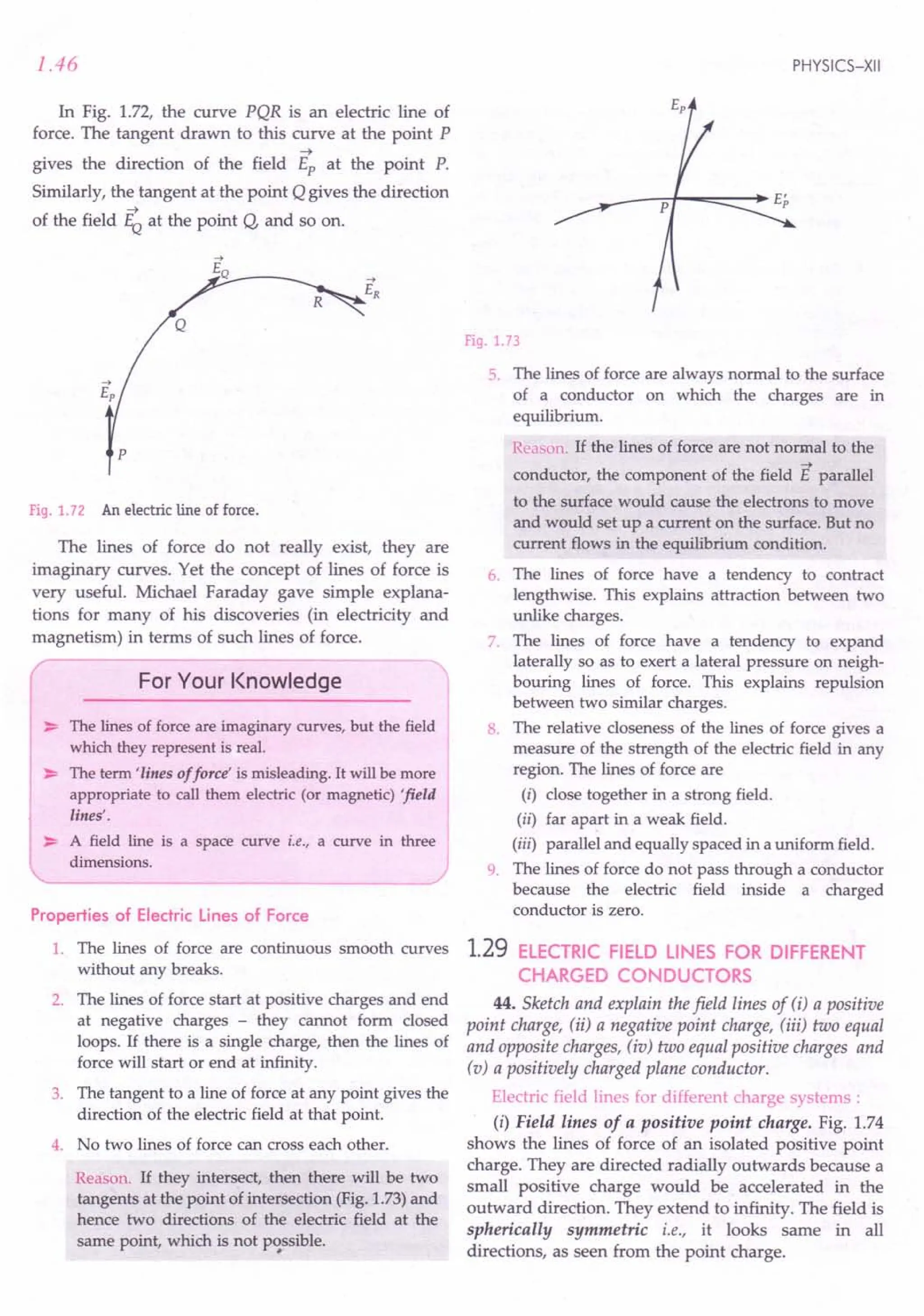
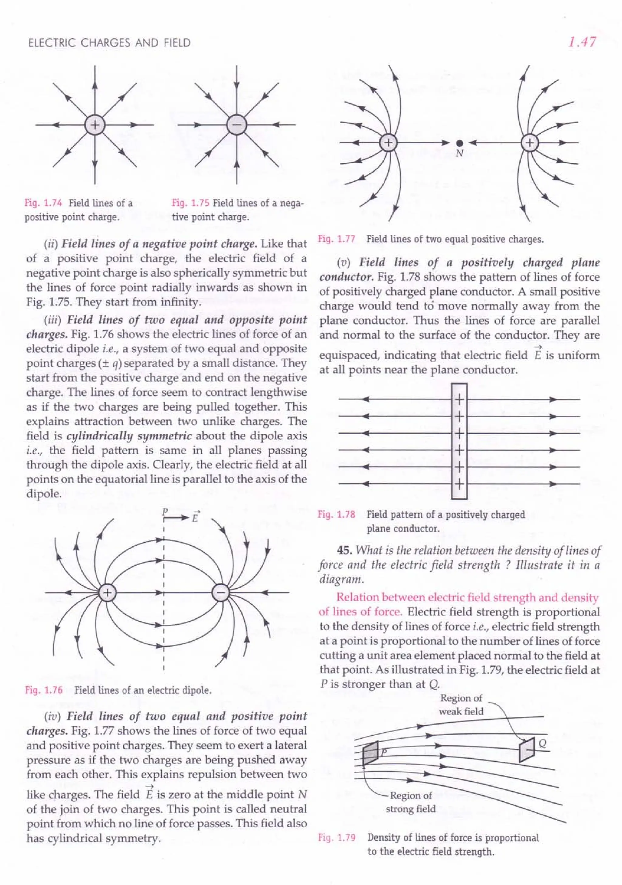
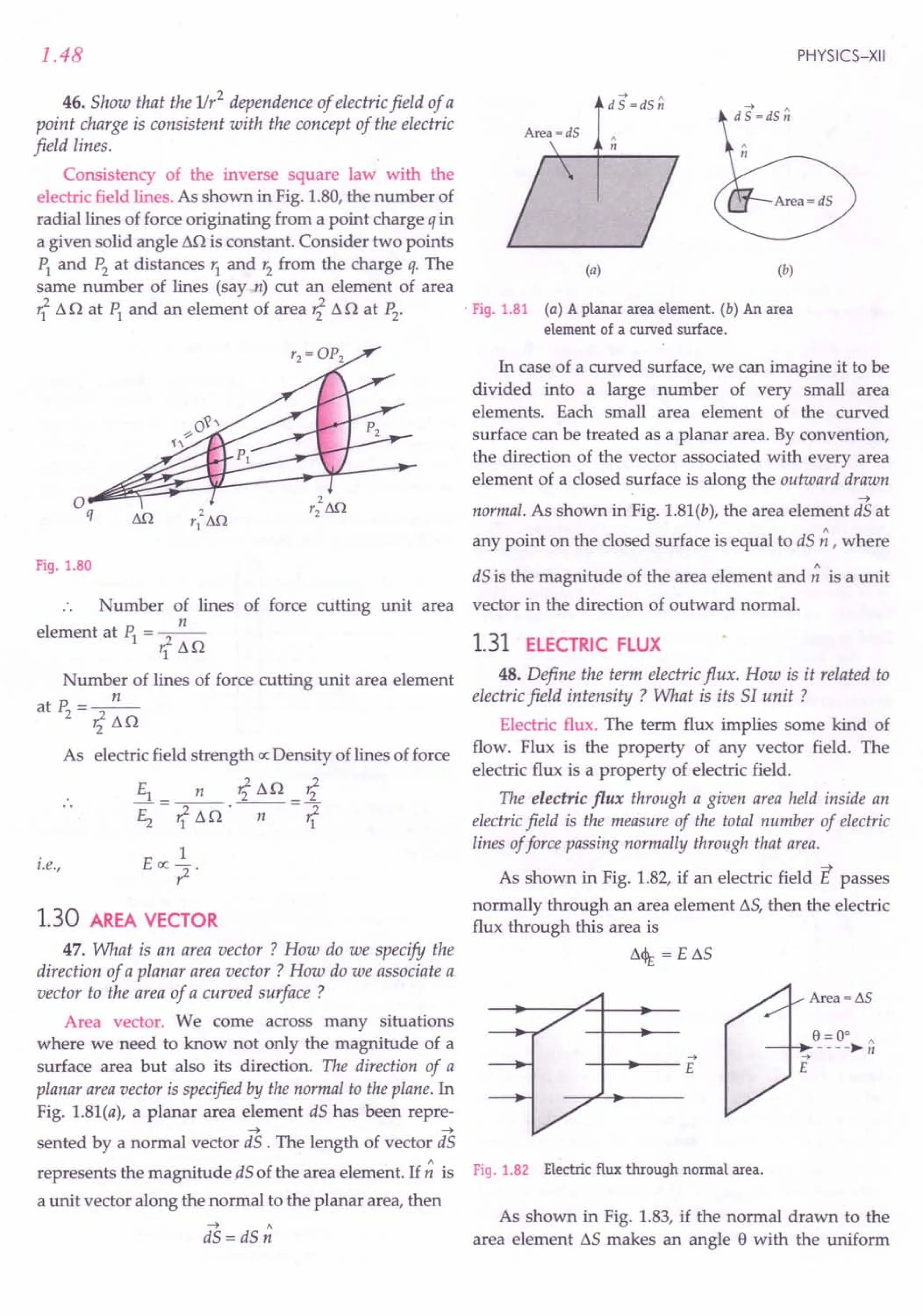
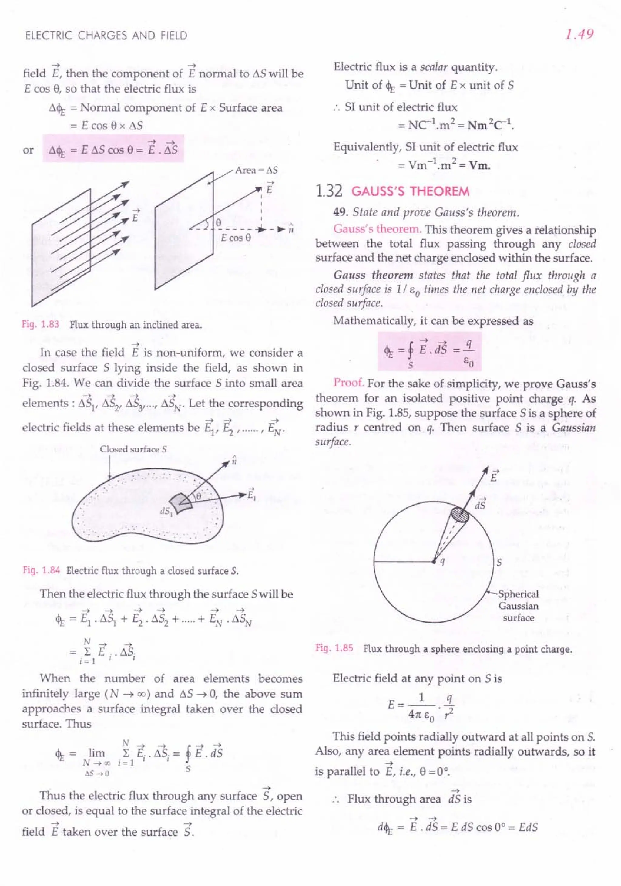
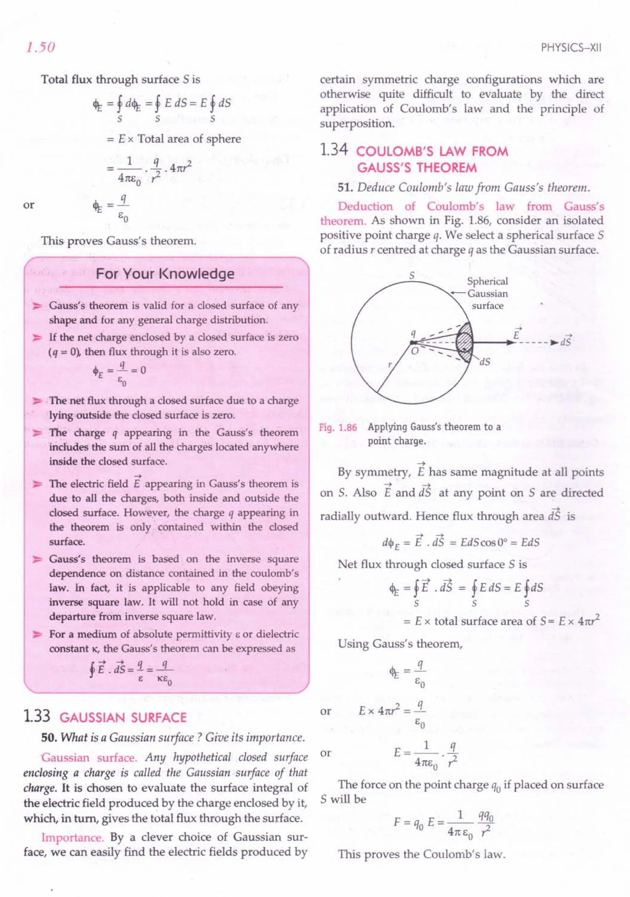
![ELECTRIC CHARGES AND FIELD
Examples based on
Electric Flux and Gauss's Theorem
Formulae Used
1. Electric flux through a plane surface area 5 held in
-->
a uniform electric field E is
--> -->
<1>£ = E .5 = EScos e
where e is the angle which the normal to the
-->
outward drawn normal to surface area 5 makes
-->
with the field E.
2. According to Gauss's theorem, the total electric flux
through a closed surface 5 enclosing charge q is
4>£ =f E.dS=!L
s Eo
FI d
. Total flux cjI£
3. ux ensity = = -
Area 5
Units Used
Electric flux 4>£ is in Nm 2 C-1
and flux density in
NC
1
.
Constant Used
Permittivity constant of free space is
EO= 1 =8.85 x 10⁻¹² C2 N-1m-2
4n x 9 x 10-9
~ " 1 "
ExampleS? IfE =6i +3j +4k .calculaie the electric
flux through a surface of area 20 units in Y-Z plane.
[Haryana 97]
~ / 1 1
Solution. Electric field vector, E =6 i + 3j + 4 k
-->
As the area vector 5 in the Y-Z plane points along
outward drawn normal i.e., along positive X-direction, so
--> "
S =20 i
-» ~ 1 1 1 "
Flux, <It = E . S = (6 i + 3 j + 4 k ).20 i
= 120 units.
Example 58. A circular plane sheet r radius 10 em is
placed in a uniform electric field of5 x 10 Ne1
, making an
angle of 60°with thefield. Calculate electric flux through the
sheet.
Solution. Here r = 10 ern = 0.1 m, E = 5 x 10⁵
NC-1
As the angle between the plane sheet and the
electric field is 60°, angle made by the normal to the
plane sheet and the electric field is e =90° -60° =300
Flux, <It = ES cos e = Ex n? x cos e
= 5 x 105
x 3.14 x (0.1)2 x cos 30°
= 1.36 x 10⁴
Nm2
C1
•
1.51
Example 59. A cylinder is placed in a uniform electric field
-->
E with its axis parallel to the field. Show that the total
electric flux through the cylinder is zero.
Solution. The situation is shown in Fig. 1.87.
is
Fig. 1.87
Flux through the entire cylinder,
<It=fE.dS + fE.iS + fE-iS
left plane right plane curved
face face surface
= f E dS cos 180° + f E dS cos 0°+ f E dS cos 90°
= - E f dS + E f dS + 0
= - E x nr2
+ E x n? = O.
Example 60. Calculate the number of electric lines offorce
originating from a charge of 1 C. .
Solution. The number of lines of force originating
from a charge of 1C
= Electric flux through a closed
surface enclosing a charge of 1C
q 1 II
- 12 = 1.129 x 10 .
EO 8.85 x 10-
Example 61. A positive charge of17.7 ~C is placed at the
centre of a hollow sphere of radius 0.5 m. Calculate the flux
density through the surface of the sphere.
Solution. From Gauss's theorem,
Flux, <It =!L.= 17.7 x 10-
6
=2 x 10⁶ Nm2 c1
EO 8.85 x 10⁻¹²
FI d
. Total flux
ux ensity = ---~
Area
2 x 10
6
5-1
--~2 =6.4x 10 NC .
4n (0.5)
Example 62. Calculate the electric flux through each of the
six faces of a closed cube of length l, if a charge q is placed
(a) at its centre and (b) at one of its vertices.
Solution. (a) By symmetry, the flux through each of
the six faces of the cube will be same when charge q is
placed at its centre.
<It = ~.!L.
6 EO](https://image.slidesharecdn.com/slaroraclass12thphysicsbyrockytrickster-250318042948-c8b51a5a/75/SL-ARORA-CLASS-12TH-PHYSICS-BY-ROCKY-TRICKSTER-pdf-52-2048.jpg)
![1.52
(b) When charge q is placed at one vertex, the flux
through each of the three faces meeting at this vertex
-+
will be zero, as E is parallel to these faces. As only
one-eighth of the flux emerging from the charge q
passes through the remaining three faces of the cube,
so the flux through each such face is
<Pt: = !.!.!L =~.!L
3 8 EO 24 EO
Example 63. The electric field components in Fig. 1.88 are
Ex = a xl/2, Ey = Ez =0, in which a =800 N / C~. Calcu-
late (i) theflux <Pt: through the cube and (ii) the charge within
the cube. Assume that a = 0.1 m [NCERT]
y
a
~----4---~-----+---+----~x
Z
Fig. 1.88
Solution. (i) The electric field is acting only in
X-direction and its Y-and Z-components are zero. For
-+
the four non-shaded faces, the angle between E and
-+ -+ -+
toS is + 1t / 2. So flux ~ = E. toS is zero through each of
these faces.
The magnitude of the electric field at the left face is
EL = ax1
/
2
= a a1
/
2
[x = a at the left face]
-+ -+
Flux, <It = EL . toS = EL toS cas 9
= EL a2
cas 180° = - EL a2
[9 = 180° for the left face]
The magnitude of the electric field at the right face is
ER = a xl/2 = a (2 a)1/2
[x =2a at the right face]
Flux, <IR= ER toS cas 0° = ER a2
[9 = 0° for the right face]
Net flux through the cube
cJt = <It +<IR = ERa2
- ELa2
= a2 (ER - EL
) = aa2 [(2a)1/2 - a1/2]
= aa5
/
2
[./i -1] =800 (0.1)5/2 (./i -1)
= 1.05 Nm2
C1
•
PHYSICS-XII
(ii) By Gauss's theorem, the total charge inside the
cube is
q = EO cJt = 1 9 x 1.05 = 9.27 x 10⁻¹²
C.
41t x 9 x 10
Example 64. An electric field is uniform, and in the
positive x direction for positive x and uniform with the same
magnitude in the negative x direction for negative x. It is
given that
and
-+ " 1
E = 200 i NC for x > 0
-+ " 1
E = - 200 i NC for x < o.
A right circular cylinder of length 20 emand radius 5 em
has its centre at the origin and its axis along the x-axis so
that oneface is at x = + 10 emand the other is at x = -10 em
(i) What is the net outward flux through eachflat face?
(ii) What is the flux through the side of the cylinder?
(iii) What is the net outward flux through the cylinder?
(iv) What is the net charge inside the cylinder? [NCERT]
y
San
->
-£
->
£
o,~--------~--+-->'-~x
65
14-------- 20
an
Fig. 1.89
-+ "
Solution. (i) On the left face: E= - 200 i NC1
,
-+ " 2" 2
toS = - toS i = - 1t (0.05) i m
The outward flux through the left face is
-+ -+
cJt = E . toS
= + 200 x 1t (0.05)2 i .i Nm2 C1
.
=+ 1.57 Nm2 C1• [i" . t =1]
On the right face;
E =200 i NCJ
~ 1 21
toS = toS i = 1t (0.05) i
The outward flux through the right face is
-+ -+ 2 1
cJt = E .as =+ 1.57 Nm C.
-+ -+
(ii) For any point on the side of the cylinder E J.. toS ,
:. Flux through the side of the cylinder,
-+ -+
cJt = E. toS = E toS cas 90° = o.](https://image.slidesharecdn.com/slaroraclass12thphysicsbyrockytrickster-250318042948-c8b51a5a/75/SL-ARORA-CLASS-12TH-PHYSICS-BY-ROCKY-TRICKSTER-pdf-53-2048.jpg)
![ELECTRIC CHARGES AND FIELD
(iii) Net outward flux through the cylinder,
<It = 157 + 157 + 0= 3.14 Nm 2 c'.
(iv) By Gauss's theorem, the net charge inside the
cylinder is
q = EO <It =8.854 x 10-12 x 3.14 = 2.78 x 10⁻¹¹
C.
Example 65. You are given a charge + Q at the origin 0
(Refer to Fig. 1.90). Consider a sphere 5 with centre (2, 0, 0)
of radius .J2 m. Consider another sphere of radius .J2 m
centered at the origin. Consider the spherical caps (i) P5Q
(ii) PRQ (iii) PWQ, with normals outward to the respective
spheres, and (iu) the flat circle PTQ with normal along the
x-axis.
(a) What is the sign of electric flux through each of the
surfaces (i)-(iv) ?
(b) What is the relation between the magnitudes of
fluxes through surfaces (i)-(iv) ?
(c) Calculate the flux through the surface (ii) directly.
Assume that the area of the cap (ii) is A. [NCERT]
y
Fig. 1.90
Solution. For the charge + Q situated at origin 0, the
-+
field E points along +vex-direction i.e., towards right.
(a) The outward drawn normal on cap P5Q points
towards left while it points towards right for
caps PRQ, PWQ and circle PTQ. SO the flux is
negative for (i) and positive for the rest.
(b) The same electric field lines crossing (i) also
cross (ii), (iii). Also, by Gauss's law, the fluxes
through (iii) and (iv) add upto zero. Hence, all
magnitudes of fluxes are equal.
(c) Given area of the cap (ii) = A
Electric field through cap (ii) is
E = _1_. Q =9 x 10⁹ x ----.fL
41[E
O
? (.J2)2
= 4.5 x 10⁹ Q NC-1
Electric flux through the cap (ii) is
<It = EA
= 4.5 x 10⁹ QA NC-1m 2.
1.53
Example 66. Figure 1.91 shows five charged lumps of
plastic and an electrically neutral coin. The cross-section of a
Gaussian surface 5is indicated. What is the net electricflux
through the surface if
q1 = q4 =+3.1 n C, q2 = qs =-5.9 nC
and q3 = -3.1 nC?
Fig. 1.91
Solution. The neutral coin and the outside charges
q4and qs make no contribution towards the net charge
enclosed by surface 5. Applying Gauss's theorem, we
get
<It = !L = q1 + q2 + q3
EO EO
+ 3.1 x 10⁻⁹ -5.9x 10⁻⁹ -3.1x 10⁻⁹
8.85 x 10-12
= -666.67 Nm2 C-1•
Example 67. 51 and 52 are two concentric spheres enclosing
charges Q and 2Q respectively as shown in Fig. 1.92.
(i) What is the ratio of the
electric flux through 51
and 52 ?
(ii) How will the electric
flux through the sphere
51 change, if a medium
of dielectric constant K is
introduced in the space
inside 51 in place of air? Fig. 1.92
(iii) How will the electricflux through sphere 51 change,
if a medium of dielectric constant K is introduced in
the space inside 52 in place of air ?
[CBSE 00 02, 14, 14C]
Solution. (i) By Gauss's Theorem,
Flux through 51 is <1 = Q
EO
th __ 2Q+ Q __3Q
Flux through 52 is 't2
EO EO](https://image.slidesharecdn.com/slaroraclass12thphysicsbyrockytrickster-250318042948-c8b51a5a/75/SL-ARORA-CLASS-12TH-PHYSICS-BY-ROCKY-TRICKSTER-pdf-54-2048.jpg)
![2. The electric field in a certain region of space is
(5 i+ 41- 4 k) x 105 NC1
. Calculate electric flux
due to this field over an area of(2 i-1) x 10- 2 m 2. Z
(Ans. 6 x 10³
Nm2
C1
) Fig.1.94
1.54
Ratio of electric flux through 51 and 52 is
4>r = Q /Eo =! = 1: 3
~ 3 QI EO 3
(ii) If a medium of dielectric constant 1C is intro-
duced in the space inside 51' then flux through 51
becomes
(iii) The flux through 51 does not change with the
introduction of dielectric medium inside the sphere 52'
~rOblems For Practice
1. If the electric field is given by
~ 1 1 1 1
E = 8 i + 4j + 3k NC- , calculate the electric flux
through a surface of area 100m 2 lying in the X- Y
plane. (Ans. 300 Nm2 C1
)
--> A
3. Consider a uniform electric field E = 3 x10³i NC-1.
Calculate the flux of this field through a square
surface of area 10em2 when
(i) its plane is parallel to the y-z plane, and
(ii) the normal to its plane makes a 60° angle with
the x-axis. [CBSE D 13C]
[Ans. (i) 30Nm2c-1 (ii) 15Nm2c-1]
4. Given a uniform electric field E = 5x10³ i NC-1,
find the flux of this field through a square of 10 cm
on a side whose plane is parallel to the Y-Z plane.
What would be the flux through the same square if
the plane makes a 30° angle with the X -axis?
[CBSE D 14]
[Ans. (i) 50 Nm2
C1
(ii) 25 Nm2c-1]
5. A point charge of 17.7IlCis located at the centre of a
cube of side 0.03m. Find the electric flux through
each face of the cube. [Himachal 93]
(Ans. 3.3 x 10⁵
Nm2 C
1
)
6. A spherical Gaussian surface encloses a charge of
8.85 x 10- 8 C. (i) Calculate the electric flux passing
through the surface. (ii) If the radius of the
Gaussian surface is doubled, how would the flux
change? [CBSE DOl, F 07]
[Ans. (i) 104
Nm2 C1
(ii) No change]
PHYSICS-XII
7. A charge q is situated at the centre of an imaginary
hemispherical surface, as shown in Fig. 1.93.Using
Gauss's theorem and symmetry considerations, deter-
mine the electric flux due to this charge through the
hemispherical surface. (Ans. ...!LJ
2Eo
eq
Fig.1.93
8. A hollow cylindrical box of length 1 m and area of
cross-section 25 em2 is placed in a three dimen-
sional coordinate system as shown in Fig. 1.94.The
--> A
electric field in the region is given by E = sax i,
where Eis in NC-1
and x is in metres.
y
~--------r-+------+~r----'X
Find
(i) net flux through the cylinder,
(ii) charge enclosed by the cylinder. [CBSE D 13]
-+ fux 1
9. The electric field in a region is given by E = - i .
b
Find the charge contained in the cubical volume
bounded by the surfaces x = a, x = a, y = a,
y = a, z = a and z = a. Take fu = 5 x 10³ NC-1,
a = 1em and b = 2 em. (Ans. 2.2 x10⁻¹²C)
10. The electric field components due to a charge inside
the cube of side 0.1 m are as shown.
Ex = ax, where a = 500 N /C-m
~=O, ~=O.
y
z
Fig.1.95](https://image.slidesharecdn.com/slaroraclass12thphysicsbyrockytrickster-250318042948-c8b51a5a/75/SL-ARORA-CLASS-12TH-PHYSICS-BY-ROCKY-TRICKSTER-pdf-55-2048.jpg)
![ELECTRIC CHARGES AND FIELD
Calculate (i) the flux through the cube, and (ii) the
charge inside the cube. [CBSE OD 08]
[Ans. (i) $E = 0.656 Nm -2C
1
(ii) q = 5.8 x10⁻¹² CJ
-4 A
11. A uniform electric field E = Ex i N / C for x > 0and
-4 A
E = - Ex i N / C for x < 0are given. A right circular
cylinder of length I em and radius, em has its centre
at the origin and its axis along the x-axis. Find out
the net outward flux. Using Gauss's law write the
expression for the net charge within the cylinder.
[CBSE D 08C]
HINTS
-4 / 1 1 1 -4 /I. 2
1. E = 8 i + 4 j + 3 k NC , 5 = 100 k m
~ ~ 1 1 1
Flux, $E = E. 5 = (8 i + 4j + 3 k ).100 k
=300Nm2
C1
•
~....... 1 1 1 5 A / 2
2. $E=E.5 =(5i+4j-4k)xlO .(2i-j)xlO-
= [5 x 2 + 4 x (- 1)- 0] x 103
Nm 2 C1
.
= 6 x10³
Nm2
C-1
•
3. (i) Normal to the area points in the direction of
the electric field, 9 = 00
•
$E = E5 cos 9 = 3 x103 x(0.10)2cos 00
= 30 Nm2
C1
.
(ii) $E = 3x103 x(0.10)2 xcos 60°= 15Nm2C1
.
4. (I) $E = EScos9
= 5 x 103 x(0.10)2cosOo= 50 Nm2
C1
•
(il) $E =5x103 x(0.1O)2cos(900-300)
=5x103 x(0.10)2 x..! = 25 Nm2C1•
2
5. Flux through each phase of the cube
1 1 q 1 17.740-6
="6 $E="6 Eo ="6 x 8.85 x 10 12
= 3.3 x10⁵
Nm2
C-1
•
. q 8.85 x 10⁻⁸
C
6. (I) $E = EO= 8.85 x 10⁻¹²C2 N-1 m-2
=104 Nm2
C-1
(ii) $E = 104Nm 2 C-1
, because the charge enclosed
is the same as in the case (i).
7. From Gauss's theorem, total flux through entire
spherical surface is
~=..i
E E
o
From symmetry considerations, flux through the
hemispherical surface is
$ =l. s.
E 2' Eo
1.55
8. (i) Flux through the curved surface of the cylinder
is zero.
Magnitude of the electric field at the left face,
E = 50x1= 50NC1
:. Flux through the left face,
$1.= EScos9=50x25xlO-4cosl80°
= -1250 x10-4NmZc-l
Magnitude of the electric field at the right face,
E= 5Ox2= 100NC1
:. Flux through the right face,
h = 1OOx25x10-4cosOo
= 2500 x 10-4Nm Zc-l
Net ~ux through the cylinder,
$E = $1.+$R = (2500-1250) x 10-4Nm Zc-l
= 1250 x10-4Nm Zc-l
= 1.250 x10⁻¹
Nm2
C-1
.
(ii) Total charge enclosed by the cylinder,
q = EO$
E = 8.854 x10-12x 1250 x 10-4C
= 11067.5x 1O-16C= 1.107 pC
9. $E = <PI. + $R
= _ EI. a2 + ERa2 = _ EU . 0 . a2 + EU· a . a2
b b
= a
3
EU = 5 x 10
3
x(0.01)3 = 0.25 Nm2 ct.
b 0.02
q = Eo$E= 8.85 x 10-12 x 0.25 = 2.2 x10-u C.
y
- - - - - - -"'j
,
, I
____ oJ I
I I
I I
I -r-+E
I I
I I
~----~--~--~~X
,
,
/- -
I
I
I
I
I
I
I
I
z
Fig. 1.96
11. Proceed as in Example 64 on page 1.52.
(i) $E = Ex . 7t(_,_)2 + S.7t(_,_)2 + 0
100 100
=27tT2Ex
(10)-4 NmZc-l.
(ii) q=EoE=27tT2
EoEx(10)-4 C](https://image.slidesharecdn.com/slaroraclass12thphysicsbyrockytrickster-250318042948-c8b51a5a/75/SL-ARORA-CLASS-12TH-PHYSICS-BY-ROCKY-TRICKSTER-pdf-56-2048.jpg)
![1.56
1.35 FIELD DUE TO AN INFINITELY
LONG CHARGED WIRE
52. Apply Gauss's theorem to calculate the electric
field of a thin infinitely long straight line of charge, with a
uniform charge density of ): em-1
.
Electric field due to an infinitely long straight
charged wire. Consider a thin infinitely long straight
wire having a uniform linear charge density A Cm - 1.
By symmetry, the field E of the line charge is directed
radially outwards and its magnitude is same at all
points equidistant from the line charge. To determine
the field at a distance r from the line charge, we choose
a cylindrical Gaussian surface of radius r, length Iand
with its axis along the line charge. As shown in Fig.
1.97, it has curved surface 51 and flat circular ends 52 and
53'Obviously, aS1
II E, iS2
.l E and iS3.l E .So only
the curved surface contributes towards the total flux.
_---- : ~dS,
,- .. 90°
(s + E
' .....
~ + --';:
I
I
I
I
I
I
I
I
r""] ~ ~E
~ :
dS,
+
+
+
+
+ I
I
I
r ---o!
I
I
I
I
I ••••. - + ...
_.. I
::, S3 + r~~1
E
------ + --- --
+ is)
I+--r--+t
+
+
+
Fig. 1.97 Cylindrical Gaussian surface for line charge.
<It = f E. dS = f E. dS1 + f E. dS2 + f E. dS3
5 S:i 52 53
= f Ed51
cos 0° + f Ed52
cos 90°+ f Ed53
cos 90°
S:i ~ ~
= E fd51 +0 + 0
= E x area of the curved surface
or <It = E x Tnr!
Charge enclosed by the Gaussian surface, q = Al
Using Gauss's theorem, <It = q / EO' we get
Al A
or E .21t rl = - or E = --
EO 21t Eor
Thus the electric field of a line charge is inversely
proportional to the distance from the line charge.
PHYSICS-XII
1.36 ELECTRIC FIELD DUE TO A UNIFORMLY
CHARGED INFINITE PLANE SHEET
53. Apply Gauss's theorem to calculate the electric
field due to an infinite plane sheet of charge.
Electric field due to a uniformly charged infinite
plane sheet. As shown in Fig. 1.98, consider a thin,
infinite plane sheet of charge with uniform surface
charge density cr. We wish to calculate its electric field
at a point P at distance r from it.
+ Plane sheet,
-+- -
- .•..•._ .•. + -+- charge density cr
+ -r + + +
.,.-+-+-+--+--+-
,..-,:----1 + +..,.. .j +
,j.. -+- + '
-+-' crA '
.•. I
-+- - - - - T - - - - - - -
+ + '
..•. + .'
~~--1 ...
+-+-~~r---~~
-+- + -e- ,....---.-~
.-+-tt-+-"'
-+- •
E
->
E
Cross-sectional
area A
Fig. 1.98 Gaussian surface for a uniformly
charged infinite plane sheet.
By symmetry, electric field E points outwards
normal to the sheet. Also, it must have same magni-
tude and opposite direction at two points P and P'
equidistant from the sheet and on opposite sides. We
choose cylindrical Gaussian surface of cross- sectional
area A and length 2r with its axis perpendicular to the
sheet.
As the lines of force are parallel to the curved
surface of the cylinder, the flux through the curved
surface is zero. The flux through the plane-end faces of
the cylinder is
<It = EA + EA =2 EA
Charge enclosed by the Gaussian surface,
q= crA
According to Gauss's theorem,
<It .:«
EO
2 EA = cr A or E = ~
EO 2Eo
Clearly, Eis independent of r, the distance from the
plane sheet.
(i) If the sheet is positively charged (o > 0), the field
is directed away from it.
(ii) If the sheet is negatively charged (o <0), the field
is directed towards it.
For a finite large planar sheet, the above formula
will be approximately valid in the middle regions of
the sheet, away from its edges.](https://image.slidesharecdn.com/slaroraclass12thphysicsbyrockytrickster-250318042948-c8b51a5a/75/SL-ARORA-CLASS-12TH-PHYSICS-BY-ROCKY-TRICKSTER-pdf-57-2048.jpg)
![ELECTRIC CHARGES AND FIELD
54. Two infinite parallel planes have uniform charge
densities of a1 and a2' Determine the electric field at
points (i) to the left of the sheets, (ii) between them, and
(iii) to the right of the sheets.
Electric field of two positively charged parallel
plates. Fig. 1.99 shows two thin plane parallel sheets of
charge having uniform charge densities a1 and a2
'with a1
> a2
>O.Suppose; is a unit vector pointing
from left to right.
0"] 0"2
E] + E] + E]
• •• ••
+ +
+ +
+ II + III
+ +
E2
+ E2
+ E2
....-- + ....-- + --.
+ +
+ +
+
. +
r
--.
Sheet 1 Sheet 2
Fig. 1.99
In the region I : Fields due to the two sheets are
~ a1" ~ a2"
E1 =---r, E =---r
2 So 2 2 So
From the principle of superposition, the total
electric field at any point of region I is
~ ~ ~ r
E[ =E1 + E2 =-- (a1 + (2)
2 So
In the region II : Fields due to the two sheets are
~ a1" ~ _ a2"
E1 = -- r, 1:._- - -- r
2 So 2 2 So
"
~ r
.'. Total field, Ell =- (a1 - (2)
2so
In the region III : Fields due to the two sheets are
E = a2 ;
2 2s
o
~ r
., Total field, Em = - (a1 + (2)
2 So
55. Two infinite parallel planes have uniform charge
densities ± a. Determine the electric field in ti) the region
between the planes, and (ii) outside it.
Electric field of two oppositely charged plane
parallel plates. As shown in Fig. 1.100, consider two
plane parallel sheets having uniform surface charge
1.57
densities of ± a. Suppose; be a unit vector pointing
from left to right.
+0" -0"
III
+
+
+
+
II
.
+ r
--.
Sheet 1 Sheet 2
Fig. 1.100
In the region I : Fields due to the two sheets are
"
~ r
E =--a
12' So
" "
~ ~ ~ r r
Total field, E[ = El + E2 = - - a + - a = 0
2 So 2 So
In the region II : Fields due to the two sheets are
~ r r a"
EII = - a + -- a = - r
2 So 2 So So
In the region III : Fields due to the two sheets are
Total field,
E =_r_a
1 2 '
So
E = __ r_ a
2 2 S
o
~
Total field, Em =0.
Thus the electric field between two oppositely
charged plates of equal charge density is uniform
which is equal to ~ and is directed from the positive to
So
the negative plate, while the field is zero on the outside
of the two sheets. This arrangement is used for
producing uniform electricfield.
1.37 FIELD DUE TO A UNIFORMLY
CHARGED THIN SPHERICAL SHELL
56. Apply Gauss's theorem to show that for a
spherical shell, the electric field inside the shell vanishes,
whereas outside it, thefield is as if all the charge had been
concentrated at the centre.](https://image.slidesharecdn.com/slaroraclass12thphysicsbyrockytrickster-250318042948-c8b51a5a/75/SL-ARORA-CLASS-12TH-PHYSICS-BY-ROCKY-TRICKSTER-pdf-58-2048.jpg)
![1.58
Electric field due to a uniformly charged thin
spherical shell. Consider a thin spherical shell of
charge of radius R with uniform surface charge density
~
cr. From symmetry, we see that the electric field E at
any point is radial and has same magnitude at points
equidistant from the centre of the shell i.e., the field is
spherically symmetric. To determine electric field at any
point P at a distance r from 0, we choose a concentric
sphere of radius r as the Gaussian surface.
E
Gaussian
,,/ - - _~ surface
.: ~;::::::JC:::::::::--.... "
I ,
I
I
I
I
£..--+-'-H Ir-----'-++-.;'r--~ E = _1 .i.
~ IP 4rcso ,;l
,
I
I
" '~r:::::::::::;..-" ~ Spherical shell,
............. "'....
;' charge density = 0'
£
Fig. 1.101 Gaussian surface for outside points of
a thin spherical shell of charge.
(a) When point P lies outside the spherical shell. The
total charge q inside the Gaussian surface is the charge
on the shell of radius R and area 4n:R2
.
q = 4n:R2
c
Flux through the Gaussian surface,
cl>E = E x 4n:?
By Gauss's theorem,
q
cl>E =-
go
£ x 41t? = .!i.
go
t: __ 1_ !L
- 4n: go . ?
This field is the same as that produced by a charge q
placed at the centre 0. Hence for points outside the shell,
the field due to a uniformly charged shell is as if the entire
charge of the shell is concentrated at its centre.
(b) When point P lies on the spherical shell. The Gaussian
surface just encloses the charged spherical shell.
Applying Gauss's theorem,
£ x 41tR2 = .!i.
go
or [For r » R]
PHYSICS-XII
E= q
4n: goR2
t: = 5!..
go
(c) When point P lies inside the spherical shell. As is
clear from Fig. 1.102, the charge enclosed by the
Gaussian surface is zero, i.e.,
or [For r= R]
or
q=O
Gaussian
surface
r---i~-++---i~£
Fig. 1.102 Gaussian surface for inside points
of a thin spherical shell of charge.
Flux through the Gaussian surface,
<IE = E x 4n?
Applying Gauss's theorem,
<IE = .!i.
go
Ex 4n? =0
or E = 0 [For r < R]
Hence electricfield due to a uniformly charged spherical
shell is zero at all points inside the shell.
Figure 1.103 shows how E varies with distance r
from the centre of the shell of radius r. E is zero from
r = 0 to r = R ; and beyond r = R, we have
1
E oc ? .
t:
r
Fig. 1.103 Variation of E with T for a
spherical shell of charge.](https://image.slidesharecdn.com/slaroraclass12thphysicsbyrockytrickster-250318042948-c8b51a5a/75/SL-ARORA-CLASS-12TH-PHYSICS-BY-ROCKY-TRICKSTER-pdf-59-2048.jpg)
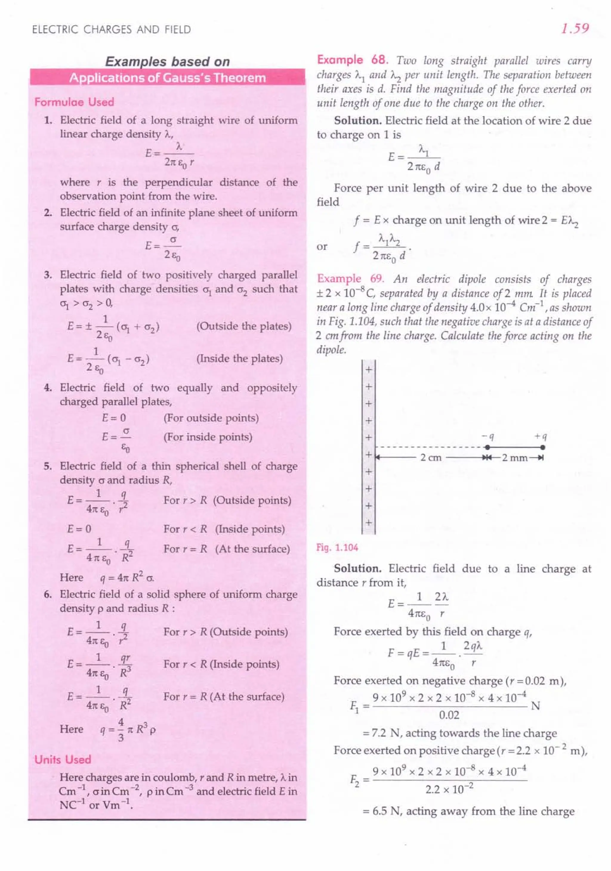
![1.60
Net force on the dipole,
F = F1- F2=7.2 -6.5
= 0.7 N, acting towards the line charge.
Example 70. (a) An infinitely long positively charged wire
has a linear charge density A.Cm-1
. An electron is revolving
around the wire as its centre with a constant velocity in a
circular plane perpendicular to the wire. Deduce the expre-
ssion for its kinetic energy. (b) Plot a graph of the kinetic
energy as afunction of charge density A.. [CBSE F 13]
Solution. The electrostatic force exerted by the line
charge on the electron provides the centripetal force
for the revolution of electron.
Force exerted by electric field = Centripetal force
mv2
eE=--
r
Here v is the orbital velocity of the electron
But E=_A._
21tco r
mv2
eA. 2 eA.
v =---
21tco m
or
r
Kinetic energy of the electron will be
1 2 eA.
Ek =-mv =--
2 41tco
(b) As Ek o: A., the graph of
kinetic energy Ek vs. charge
density A. will be a straight line
as shown in Fig. 1.105.
Fig. 1.105
Example 71. A charge of 17.7 x 10--4C is distributed
uniformly over a large sheet of area 200 ~. Calculate the
electric field intensity at a distance of20 emfrom it in air.
[CBSE OD 03C]
Solution. Surface charge density of the sheet,
CJ =!L = 17.7 x 10-
4
C =8.85 x 10⁻⁶ Cm-2
A 200 m2
Electric field at a distance of 20 cm from it in air,
E =~ = 8.85 x 10-
6
=5x 10⁵ NC-1.
2co 2 x 8.85 x 10-12
Example 72. A charged particle having a charge of
- 2.0 x 10⁻⁶
C is placed close to a non-conducting plate
having a surface charge density of 4.0 x 10⁻⁶ Cm-2. Find the
force of attraction between the particle and the plate.
Solution. Here q = - 2.0 x 1O-6
C
CJ = 4.0 x 1O-6
Cm-2
Field produced by charged plate,
E=~
2co
PHYSICS-XII
Force of attraction between the charged particle
and the plate,
F=qE= CJq = 4x10-
6
x2.0xlO-
6
2 Co 2 x 8.85 x 10-12
= 0.45 N.
Example 73. A particle of mass 9x10⁻⁵g is kept over a
large horizontal sheet of charge density 5 x 10⁻⁵Cm-2. What
charge should be given to the particle, so that if released, it
does not fall ?
Solution. Here m = 9 x 10⁻⁵ g = 9 x 10⁻⁸ kg,
CJ = 5 x 10⁻⁵
Cm-2
The particle must be given a positive charge q.It will
not fall if
Upward force exerted on the = Weight ofihe particle
particle by electric field
qE=mg
CJ
q.-=mg
2co
2comg
q=--
CJ
2 x 8.85 x 10-12 x 9 x 10-8 x 9.8
5 x 10-5
= 3.12 x 10⁻¹³ C.
Example 74. A large plane sheet of charge having surface
charge density 5.0 x 10⁻¹⁶ Cm 2 lies in the X-Y plane. Find
the electricflux through a circular areaof radius 0.111'(.
if the
normal to the circular area makes an angle of 60° with the
Z-axis.
Given that: Co=8.85 x 10⁻¹² C2 N-1
m-2
.
Solution. Here CJ = 5.0 x 10⁻¹⁶ Cm -2, r = 0.1 m,
or
or
or
8 =60°
Field due to a plane sheet of charge,
E=~
2co
Flux through circular area,
<If: = EllS cos 8 = ~ x n,1 cos 8
2co
5.0 x 10-16 x 3.14 x (0.1)2 cos 60°
2 x 8.85 x 10-12
= 4.44 x 10⁻⁷ Nm2C-1•
Example 75. A spherical conductor of radius 12 em has a
charge of 1.6 x 10⁻⁷
C distributed uniformly over its
surface. What is the electric field (i) inside the sphere,
(ii) just outside the sphere, (iii) at a point 18 cm from the
centre of the sphere? [NCERT]](https://image.slidesharecdn.com/slaroraclass12thphysicsbyrockytrickster-250318042948-c8b51a5a/75/SL-ARORA-CLASS-12TH-PHYSICS-BY-ROCKY-TRICKSTER-pdf-61-2048.jpg)
![ELECTRIC CHARGES AND FIELD
Solution. Here q = 1.6 x 10⁻⁷ C,
R =12 cm =0.12 m
(i) Inside the sphere, E = O. This is because the charge
resides on the outer surface of the spherical conductor.
(ii) Just outside the sphere, r = R =0.12 m. Here the
charge may be assumed to be concentrated at the
centre of the sphere.
E=_l_ 3..-
41tEO'R2
9 x 10
9
x 1.6 x 10-
7
= 105 NC1.
(0.12)2
(iii) At a point 18 em from the centre,
r=18cm=0.18m.
1 q 9 x 109 x 1.6 x 10-7
E = -- - = -----;;--
41tEO. r2 (0.18)2
= 4.44 x 10⁴
NC1
•
~rOblems For Practice
1. An infinite line charge produces a field of
9 x 10⁴
NC-1 at a distance of 4 cm. Calculate the
linear charge density. [Haryana 01]
(Ans. 2 x 10⁻⁷ Cm -1)
2. A cylinder of large length carries a charge of
2 x 10⁻⁸Cm -1. Find the electric field at a distance of
0.2 m from it. (Ans. 1800 Ym -1)
3. An infinitely long wire is stretched horizontally
4 metre above the surface of the earth. It carries a
charge l/-!C per cm of its length. Calculate its
electric field at a point on the earth's surface
vertically below the wire. (Ans. 4.5 xlOS
Ym -1)
4. Two large metal plates each of area 1m 2 are placed
facing each other at a distance of 10 ern and carry
equal and opposite charges on their faces. If the
electric field between the plates is 100 NC-l, find
the charge on each plate. (Ans. 8.85 x 10⁻¹⁰C)
5. An electron is revolving around a long line charge
having charge density 2 xlO-B
Cm -1. Find the kinetic
energy of the electron, assuming that it is
independent of the radius of electron's orbit.
(Ans.2.88xlO-17J)
6. A particle of mass 5 x 10⁻⁶g is kept over a large
horizontal sheet of charge density 4 xl 0-6Cm -2.
What charge should be given to this particle, so that
if released, it does not fall down. How many
electrons should be removed to give this charge?
(Ans. 2.16 x10⁻¹³C, 1.355 x 10⁶
)
1.61
7. A spherical shell of metal has a radius of 0.25 m and
carries a charge of 0.2 /-!c.Calculate the electric field
intensity at a point (i) inside the shell, (ii) just
outside the shell and (iii) 3.0 m from the centre of
the shell. [Ans. (i) 0 (ii) 2.88 x 10⁴
NC1
(iii) 200 C1l
HINTS
Er 9 x 104
x 0.04
1. A= 21tEoEr = 41tE0
- = 9
2 9 x 10 x 2
= 2 x 10⁻⁷ Cm -1 •
2. Here A= 2 x 10-BCm -I, r = 0.2 m
:. E = _A_ = _1_. 2A = 9 x 109 x 2 x2 xlO-
B
21tEor 41tEo r 0.2
=1800 Vm-'l..
3. E=_l_. 2A = 9x10
9
x2x10-
4
= 4.5 x10s Vm-1.
41tEo r 4
4. E=.5!..=-q-
EO EotJ.S
:. q = EOtJ.S E = 8.85 x 10-12 x 1 x 100
= 8.85 x10- 10 C
5. From Example 70,
~ = ~ = 9 x109 x1.6x10-9 x2.0 x 10-8
41tEo
= 2.88 x10⁻¹⁷
J.
6. Upward electric force on particle
= Weight of the particle
(J
mg = qE=q.-
2Eo
2Eomg
or q=-.--
(J
2 x 8.85 x 10-12 x 5 x 10-9 x 9.8
4 x 106
= 2.16 x10⁻¹³
C.
Number of electrons required to be removed,
q 2.16 x 10⁻¹³ 6
n = - = 19 = 1.355 x10 .
e 1.6 x 10-
7. (i) Electric field at any point inside the shell = O.
(ii) E = _1_ .!L
41tEo. R2
9 x 10
9
x0.2 x 10-
6
= 2.88 x10⁴ NC-1.
(0.25)2
("')E- 1 q
III - 41tEo. ,z
9 x 10
9
xO.2x 10-6 = 200 NC-1.
(3.0)2](https://image.slidesharecdn.com/slaroraclass12thphysicsbyrockytrickster-250318042948-c8b51a5a/75/SL-ARORA-CLASS-12TH-PHYSICS-BY-ROCKY-TRICKSTER-pdf-62-2048.jpg)
![1.62 PHYSICS-XII
VERY SHORT ANSWER CONCEPTUAL PROBLEMS
Problem 1.The electric charge of any body is actually
a surplus or deficit of electrons. Why not protons?
Solution. Electrons are loosely bound to atoms and
can be readily exchanged during rubbing. Protons are
firmly bound inside the nucleus. They cannot be easily
detached. Hence electric charge of any body is just a
surplus or deficit of electrons and not protons.
Problem 2. When a glass rod is rubbed with silk,
both acquire charges. What is the source of their electri-
fication?
Solution. For the electrification of a body, only
electrons are responsible. During rubbing electrons are
transferred from glass rod to silk. The glass rod acquires a
positive charge and silk acquires an equal negative charge.
Problem 3.Is the mass of a body affected on charging?
Solution. Yes. Electrons have a definite mass. The
mass of a body slightly increases if it gains electrons while
the mass decreases if the body loses electrons.
Problem 4. Two identical metallic spheres of exactly
equal masses are taken. One is given a positive charge q
coulombs and other an equal negative charge. Are their
masses after charging equal ? [lIT]
Solution. No. The positive charge of a body is due to
deficit of electrons while the negative charge is due to
surplus of electrons. Hence the mass of the negatively
charged sphere will be slightly more than that of the
positively charged spheres.
Problem 5. A positively charged rod repels a sus-
pended object. Can we conclude that the object is posi-
tively charged?
Solution. Yes, the object is positively charged.
Repulsion is the surest test of electrification.
Problem 6. A positively charged rod attracts a
suspended object. Can we conclude that the object is
negatively charged?
Solution. No. A positively charged rod can attract
both a neutral object and a less positively charged object.
Problem 7. How does a positively charged glass rod
attract a neutral piece of paper?
Solution. The positively charged rod induces negative
charge on the closer end and positive charge on the
Fig. 1.106
farther end of the paper. The rod exerts greater attraction
than repulsion on the paper because negative charge is
closer to the rod than the positive charge. Hence the rod
attracts the piece of paper.
Problem 8. Can two like charges attract each other? If
yes, how?
Solution. Yes.If one charge is larger than the other, the
larger charge induces equal and opposite charge on the
nearer end of the body with smaller charge. The opposite
induced charge is larger than the small charge initially
present on it.
Problem 9. Why do the gramophone records get
covered with dust easily?
Solution. The gramophone records get charged due to
the rubbing action of the needle. So they attract the dust
particles from the air.
Problem 10. An ebonite rod held in hand can be
charged by rubbing with flannel but a copper rod
cannot be charged like this. Why ? [Himachal97]
Solution. Ebonite rod is insulating. Whatever charge
appears on it due to rubbing, stays on it. Copper is good
conductor. Any charge developed on it flows to the earth
through our body. Socopper rod cannot be charged like this.
It can be charged by providing it a plastic or rubber handle.
Problem 11. Electrostatic experiments do not work
well on humid days. Give reason.
Solution. Electrostatic experiments require accumu-
lation of charges. Whatever charges appear during the
experimentation, they are drained away through humid
air which is more conducting than dry air due to the
presence of a larger number of charged particles in it.
Problem 12. A comb run through one's dry hair
attracts small bits of paper. Why ? What happens if the
hair is wet or if it is a rainy day? [NCERT]
Solution. When the comb runs through dry hair, it gets
charged by friction. The molecules in the paper get
polarized by the charged comb, resulting in a net force of
attraction. If the hair is wet, or if it is rainy day, friction
between hair and the comb reduces. The comb does not
get charged and thus it will not attract small bits of paper.
Problem 13.Ordinary rubber is an insulator. But the
special rubber tyres of aircrafts are made slightly
conducting. Why is this necessary? [NCERT]
Solution. During landing, the tyres of aircraft may get
highly charged due to friction between tyres and the air
strip. If the tyres are made slightly conducting, they will
lose the charge to the earth otherwise too much of static
electricity accumulated may produce spark and result in
fire.](https://image.slidesharecdn.com/slaroraclass12thphysicsbyrockytrickster-250318042948-c8b51a5a/75/SL-ARORA-CLASS-12TH-PHYSICS-BY-ROCKY-TRICKSTER-pdf-63-2048.jpg)
![ELECTRIC CHARGES AND FIELD
Problem 14. Vehicles carrying inflammable materials
usually have metallic ropes touching the ground during
motion. Why ? [Himanchal 98 ; Punjab 99 ; NCERT]
Solution. Moving vehicle gets charged due to friction.
The inflammable material may catch fire due to the spark
produced by charged vehicle. When metallic rope is used,
the charge developed on the vehicle is transferred to the
ground and so the fire is prevented.
Problem 15. An inflated balloon is charged by
rubbing with fur. Will it stick readily to a conducting
wall or to an insulating wall? Give reason. [Roorkee]
Solution. It will stick readily to the conducting wall. It
induces an equal amount of charge on the conducting
wall and much smaller charge on insulating wall. So a
large force of attraction acts between the balloon and the
conducting wall.
Problem 16. A metal sphere is fixed on a smooth
horizontal insulating plate. Another metal sphere is
placed a small distance away. If the fixed sphere is given
a charge, how will the other sphere react ?
Solution. The charge on the fixed sphere induces
unlike charge at the closer end and like charge on the far
end of the free sphere. et attraction act on the free
sphere and so it gets accelerated towards the fixed sphere.
Problem 17. Is there some way of producing high
voltage on your body without getting a shock?
Solution. If we stand on an insulating surface and
touch the live wire of a high power supply, a high poten-
tial is developed on our body, without causing any shock.
Problem 18. A charged rod attracts bits of dry cork
which after touching the rod, often jump away from it
violently. Why?
Solution. The charged rod attracts the bits of dry cork
by inducing unlike charge at their near ends and like
charge at their far ends. When the cork bits touch the rod,
they share the charge of the rod of the same sign and so
get strongly repelled away.
Problem 19. What does q1 + q2 = 0 signify in
electrostatics? [CBSE 00 01C]
Or
Two charges q1 and q2' separated by a small distance
satisfy the equation q1 +q2 = 0. What does it tell about
the charges? [CBSE F 03]
Solution. The equation signifies that the electric
charges are algebraically additive and here q1 and q2 are
equal and opposite.
Problem 20. ame the experiment which established
the quantum nature of electric charge. [CBSE 00 98]
Solution. Millikan's oil drop experiment for deter-
mining electronic charge.
Problem 21. Can a body have a charge of 0.8 x 10-
19
C?
Justify your answer by comment? [Himachal 99C]
1.63
Solution. The charge on any body is always an integral
multiple of e. Here
0.8 x 10⁻¹⁹
C
n =:J.= = 0.5
e 1.6 x 10⁻¹⁹ C
This is not an integer. So a body cannot have a charge
of 0.8 x 10- 19 C. '
Problem 22. If the distance between two equal point
charges is doubled and their individual charges are also
doubled, what would happen to the force between
them ? [ISCE 95]
Solution. The original force between the two charges is
F __ 1_ q xq
- 41tEo·. ?
When the individual charges and the distance
between them are doubled, the force becomes
Hence the force will remain same.
Problem 23. The electrostatic force between two
charges is a central force. Why ?
Solution. The electrostatic force between two charges
acts along the line joining the two charges. So it is a central
force.
Problem 24. How is the Coulomb force between two
charges affected by the presence of a third charge?
Solution. The Coulomb force between two charges
does not depend on the presence of a third charge.
Problem 25. Two equal balls having equal positive
charge 'q' coulombs are suspended by two insulating
strings of equal length. What would be the effect on the
force when a plastic sheet is inserted between the two ?
[CBSEOD 14]
Solution. The force between the two balls decreases
because x{Plastic) > 1 and FIX: 1/ K.
Problem 26. Force between two point charges kept at
a distant d apart in air is F. If these charges are kept at
the same distance in water, how does the electric force
between them change? [CBSE 00 11]
Solution. Dielectric constant for water, K = 80
F =Fair=£
water K 80
Thus the force in water is 1/80 times the original force
in air.
Problem 27. The dielectric constant of water is 80.
What is its permittivity? [Haryana 97C]
Solution. Dielectric constant, K = ~
Eo](https://image.slidesharecdn.com/slaroraclass12thphysicsbyrockytrickster-250318042948-c8b51a5a/75/SL-ARORA-CLASS-12TH-PHYSICS-BY-ROCKY-TRICKSTER-pdf-64-2048.jpg)
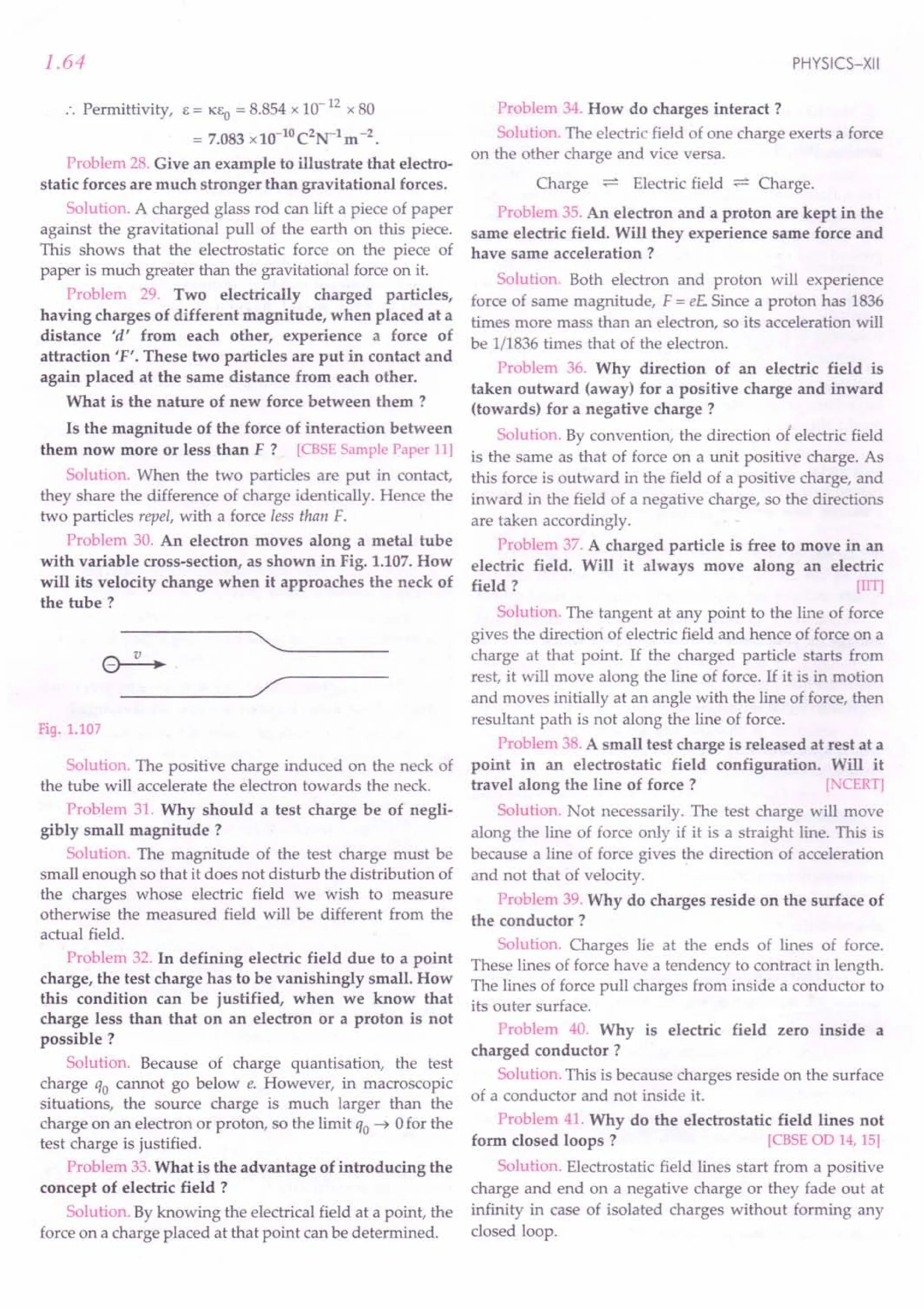
![ELECTRIC CHARGES AND FIELD
Alternatively, electrostatic field is a conservative field.
The work done in moving a charge along a closed path
must be zero. Hence, electrostatic field lines cannot form
closed loops.
Problem 42.Do the electric lines of force really exist?
What is about the field they represent?
Solution. Lines of force do not really exist. These are
hypothetical curves used to represent an electric field. But
the electric field which they represent is real.
Problem 43. Draw
lines of force to represent
a uniform electric field.
->
------------~--~~ E
[CBSE
00 95]
Solution. The lines of
force of a uniform electric
field are equidistant
parallel lines as shown in Fig.1.108 Uniform electric field.
Fig. 1.108.
Problem 44. Fig. 1.109 shows electric lines of force
due to point charges ql and q2 placed at points A and B
respectively. Write the nature of charge on them.
[CBSE
F 03]
Fig.1.109
Solution. As the lines of force are pointing towards ql
as well as Q2' so both ql and Q2 must be negative charges.
Problem 45. A positive point charge (+ q) is kept in
the vicinity of an uncharged conducting plate. Sketch
electric field lines originating from the point charge on
to the surface of the plate. [CBSE
00 09]
Solution. Starting from the charge + q, the lines of
force will terminate at the metal plate, inducing negative
charge on it. At all positions, the lines of force will be
perpendicular to the metal surface, as shown in Fig. 1.110.
+q
Fig.1.110
1.65
Problem 46. Why is it necessary that the field lines
from a point charge placed in the vicinity of a conductor
must be normal to the conductor at every point.
[CBSEF09]
Solution. If the field lines are not normal, then the field.
-4
E would have a tangential component which will make
electrons move along the surface creating surface currents
and the conductor will not be in equilibrium.
Problem 47. Fig. 1.111 shows two
large metal plates, Pl
and P2
, tightly held
against each other and placed between
two equal and unlike point charges
perpendicular to the line joining them.
(i) What will happen to the plates
when they are released ?
(ii) Draw the pattern of the electric
field lines for the system.
[CBSE
F 09] Fig.1.111
P,
+Q -Q
Solution.
(i) When released, the two plates tend to move
apart slightly due to the charges induced in them.
(ii) The pattern of the electric field lines for the
system is shown in Fig. 1.112.
- +
+Q (1--------+-----+-11++----- .•..
-------:0 - Q
- +
Fig.1.112
Problem 48. In the electric field shown in Fig. 1.113,
the electric field lines on the left have twice the
separation as that between those on the right. If the
magnitude of the field at point A is 40 NC-l, calculate
the force experienced by a proton placed at point A Also
find the magnitude of electric field at point B.
: ~
:-A
·B
;;- :
:
Fig.1.113](https://image.slidesharecdn.com/slaroraclass12thphysicsbyrockytrickster-250318042948-c8b51a5a/75/SL-ARORA-CLASS-12TH-PHYSICS-BY-ROCKY-TRICKSTER-pdf-66-2048.jpg)
![1.66
Solution. Force on proton at point A,
F = eEA = 1.6 x 10-19
x40 = 6.4 x10⁻¹⁸
N
As the separation between the lines of force at point B
is twice of that at point A, so
EB =.! EA =.! x40=20NC1
.
2 2
Problem 49. The electric lines of force tend to
contract lengthwise and expand laterally. What do they
indicate?
Solution. The lengthwise contraction indicates
attraction between unlike charges while lateral expansion
indicates repulsion between like charges.
Problem 50.A point charge placed at any point on the
axis of an electric dipole at some large distance
experiences a force F. What will be the force acting on
the point charge when its distance from the dipole is
doubled? [CPMT91]
Solution. At any axial point of a dipole, electric field
varies as
1 F 1 1
Eoc 3" or - = 3" or F oc 3"
r q r r
.. When the distance of the point charge is doubled,
the force reduces to F/ 8.
Problem 51. As shown in Fig. 1.114, a thin spherical
shell carries a charge Q on its surface. A point charge
Q 12 is placed at its centre 0 and another charge 2Q
placed outside. If all the charges are positive, what will
be the force on the charge at the centre?
Q
e2Q
e Q/2
o
Fig. 1.114
Solution. Zero, because the electric field inside the
spherical shell is zero.
Problem 52. What is the number of electric lines of
force that radiate outwards from one coulomb of charge
in vacuum?
Solution. Here q = 1C, Eo = 8.85x10⁻¹²
C2
N-1
m-2
Number of lines of force = Electric flux
=!L= 1
Eo 8.85 x 10- 12
= 1.13 x10¹¹
.
PHYSICS-XII
Problem 53.Consider the situation shown in Fig. 1.115.
What are the signs of ql and q2 ? If the lines are drawn in
proportion to the charge,
what is the ratio q1/ q2 ?
Solution. Here ~ is a
negative charge and q2 is
a positive charge.
!!l=.i.
q2 18
=1 :3. Fig. 1.115
Problem 54. An arbitrary surface encloses a dipole.
What is the electric flux through this surface?
[~xemplarProblem]
Solution. As the total charge of a dipole is zero, so by
Gauss's theorem, the electric flux through the closed
surface is zero.
Problem 55. The force on an electron kept in an
electric field in a particular direction is F. What will be
the magnitude and direction of the force experienced by a
proton at the same point in the field? Mass of the proton
is 1836 times the mass of the electron. [CBSE F07]
Solution. A proton has charge equal and opposite to
that of an electron. Hence the proton will experience a
force equal and opposite to that of F.
Problem 56.Figure 1.116shows three charges + 2q, -q
and + 3q. Two charges + 2q and -q are enclosed within a
surface '5'. What is the electric flux due to this con-
figuration through the surface '5' ? [CBSE 0 10]
+3q
•
Fig. 1.116
Sol
. Net charge enclosed by the surface S
ution. <PE = ------"'-------~-----
EO
=+2q-q =!L
EO EO
Problem 57.Two charges of magnitudes - 2Q and +Q
are located at points (a, 0) and (4a, 0) respectively. What
is the electric flux due to these charges through a sphere of
radius '3a' with its centre at the origin? [eBSE OD 13]
Solution. Only the charge -2Q is enclosed by the
sphere of radius 3a. By Gauss's theorem.
'" __ 2Q
~'E - .
EO](https://image.slidesharecdn.com/slaroraclass12thphysicsbyrockytrickster-250318042948-c8b51a5a/75/SL-ARORA-CLASS-12TH-PHYSICS-BY-ROCKY-TRICKSTER-pdf-67-2048.jpg)
![1.80 PHYSICS-XII
G IDELI N ES TO NCERT EXERCISES
1.1. What is the force between two small charged spheres
having charges of 2 x 10⁻⁷ C and 3 x 10⁻⁷Cplaced 30 em apart
in air?
Ans. Here q1 = 2 x 10⁻⁷C, q2 = 3 x 10⁻⁷C,
r = 30 cm = 0.30 m
According to Coulomb's law, .
F= _1_. q1q2 =9x109 x2x10-7 x3xlO-
7
4m;0 r2
(0.30)2
= 6 x10⁻³
N (repulsive).
1.2. The electrostatic force on a small sphere of charge
0.4 flC due to another small sphere of charge -0.8flC in air is
0.2 N. ti) What is the distance between two spheres? (ii) What
is the force on the second sphere due to the first?
Ans. (i) Here ql = 0.4 flC = 0.4 x 10⁻⁶
C
q2 = - 0.8 flC = - 0.8 x 10- 6 C, F = 0.2 N r = ?
As F __ 1_ qlq2
- 41tEo' 1'2
.. 1'2= _1_. qlq2
41tEo F·
9 x10
9
x0.4 x10-
6
x0.8 x10-
6
= 144 x10-4
0.2
r = 12 x 10-2 = 0.12 m =12 em.
(ii) The two charges mutually exert equal and opposite
forces.
.'. Force on the second sphere due to the first
= 0.2 N (attractive).
1.3. Check that the ratio ke2/Gmemp is dimensionless. Look
up a table of physical constants and determine the value of this
ratio. What does this ratio signify ?
. [ e2 1 [Nm Zc-2] x [C]2 .
Ans. k --- = = no unit
Gmemp [Nm2kg-2] x [kg][kg]
As 'the ratio k e2
/ Gmemp has no unit, so it is
dimensionless.
Now k = 9 x 10⁹ NmZc-2
G = 6.67 x 10⁻¹¹
Nm2
kg-2
e = 1.6 x 10⁻¹⁹
kg
me = 9.1 x 10⁻³¹
kg
mp = 1.66 x 10⁻²⁷ kg
; 9 x 109 x (1.6 x 10-19)2
.. k Gmcmp = 6.67x10-11 x9.1x 10 31 x 1.66x 10 27
or
and
= 2.287 x1039
•
The factor k e2 !Gmemp represents the ratio of
electrostatic force to the gravitational force between an
electron and a proton. Also, the large value of the ratio
signifies that the electrostatic force is much stronger than
the gravitational force.
1.4. (i) Explain the meaning of the statement 'electric
charge of a body is quantised.'
(ii) Why can one ignore quantisation of electric charge
when dealing with macroscopic i.e., large scale
charges?
Ans. (i) Quantisation of electric charge means that the
total charge (q) of a body is always an integral multiple of
a basic charge (e) which is the charge on an electron. Thus
q = ne, where n = 0, ± I, ± 2, ± 3, .
(ii) While dealing with macroscopic charges (q = ne),
we can ignore quantisation of electric charge. This is
because e is very small and nis very large and so q behaves
as if it were continuous i.e., as if a large amount of charge
is flowing continuously.
1.5. When a glass rod is rubbed with a silk cloth, charges appear
on both. A similar phenomenon is observed with many other
pairs of bodies. Explain how this observation is consistent with
the law of conservation of charge.
Ans. It is observed that the positive charge developed
on the glass rod has the same magnitude as the negative
charge developed on silk cloth. So total charge after
rubbing is zero as before rubbing. Hence the law of
conservation of charge is being obeyed here.
1.6. Four point charges qA = 2 flC qB = -5 tiC 'tc = 2 flC
qD = -5 flCare located at the corners of a square ABCD of side
10 cm. What is the force on a charge of1 flCplaced at the centre
of the square ?
~102 + 102
Ans. Here OA = OB = OC = OD = -'----
2
= 5.fi cm = 5.fi x 10- 2 m
qo=-5flC 10 em qc~2flC
D---------------~C
...•
o
9
Fig. 1.149](https://image.slidesharecdn.com/slaroraclass12thphysicsbyrockytrickster-250318042948-c8b51a5a/75/SL-ARORA-CLASS-12TH-PHYSICS-BY-ROCKY-TRICKSTER-pdf-68-2048.jpg)
![ELECTRIC CHARGES AND FIELD
Forces exerted on the charge of 1 IlC located at the
centre are
~
= 3.6 N, along OC
~ 9x109 x5xlO-6 x1xlO-6
F------;=------,~--
B - (5.fi x 10-2)2
~
= 9 N, along OB
~ 9x109 x2xlO-6
x1xlO-6
F,------;=-----;;,....,.---
e - (5.fi x 10-2)2
~
= 3.6 N, along OA
~ 9x109 x5x10-6
x1x10-6
F------;=------,~--
0- (5.fi x 10-2)2
~
= 9 N, along OD
-+ -+- -+ -+
Clearly, Fe = - FA and Fo = - FB
Hence total force on 11lC charge is
-+-+ -+-+---t
F = FA + FB + Fe + Fo
~ ~ ~ ~
= FA + FB - FA - FB = zero N.
1.7. (a) An electrostatic field line is a continuous curve.
That is, a field line cannot have sudden breaks. Why not ?
(b) Explain why two field lines never cross each other at any
point? [Punjab 01, 02; CBSE 0 OS,03; 00 14]
Ans. (a) Electric lines of force exist throughout the
region of an electric field. The electric field of a charge
decreases gradually with increasing distance from it and
becomes zero at infinity i.e., electric field cannot vanish
abruptly. So a line of force cannot have sudden breaks, it
must be a continuous curve.
(b) If two lines of force intersect, then there would be
two tangents and hence two directions of electric field at
the point of intersection, which is not possible.
1.8. Two point charges qA = + 3 IlC and qB = - 3 IlC are
located 20 em apart in vacuum. ti) Find the electric field at the
midpoint 0 of the line AB joining the two charges. (ii) If a
negative test charge of magnitude 1.5 x 10- 9 C is placed at the
centre, find the force experienced by the test charge.
[CBSEOO 03]
Ans. The directions of the fields EA and EB due to the
charges qA and qB at the midpoint P are as shown in
Fig. 1.150.
Electric field at the midpoint 0 due to qA'
EA
qA = + 3 IlC ----. qB = - 3 fiC
• • •
A 10em 0----. 10em B
EB
Fig. 1.150
1.81
1 qA 9 x 109 x 3 x 10-6
E = -- - = -------.---
A 41tEo' r2 (0.10)2
= 2.7 x 10⁶
Ne1
, along OB
Electric field at the midpoint 0 due to qB'
1 qB 9x109x3'xlO-6
E = -- - = -------,._-
B 41tEo' r2 (0.10)2
. = 2.7 x 10⁶
NC-1
, along OB
Resultant field at the midpoint 0 is
E = EA + EB = (2.7 + 2.7) x 106
= 5.4 x10⁶
NC-1
, along OB.
(ii) Force on a negative charge of 1.5 x 1O-9Cplaced at
the midpoint 0,
F = qE = 1.5.x10-9 x5.4 x 106
= 8.1 x10⁻³
N, along OA
The force on a negative charge acts in a direction
opposite to that of the electric field.
1.9. A system has two charges qA = 25 x 10-7
C and
qB = -25 x 10-7
C, located at points A (0,0, -15 em) and
B (0,0, + 15 em) respectively. What is the total charge and
electric dipole moment of the system ?
Ans. Clearly, the two charges lie on Z-axis on either ,','
side of the origin and at 15 em from it, as shown in 'v
Fig. 1.151. .
2a = 30cm = 0.30 m, q = 2.5 x 10⁻⁷
C
z
-7
qB = - 2.5 x 10 C B (0, 0, + 15 em)
o y
2 5 10-7C A (0, 0, -15 em)
qA = . X
x
Fig. 1.151
Total charge = qA + qB = 2.5 x 10⁻⁷
- 2.5 x 10-7
= 0
Dipole moment,
p = q x 2a = 2.5 x 10-7
x 0.30
= 0.75 x 10⁻⁷
Cm
The dipole moment acts in the direction from B to A
i.e., along negative Z-axis.](https://image.slidesharecdn.com/slaroraclass12thphysicsbyrockytrickster-250318042948-c8b51a5a/75/SL-ARORA-CLASS-12TH-PHYSICS-BY-ROCKY-TRICKSTER-pdf-69-2048.jpg)
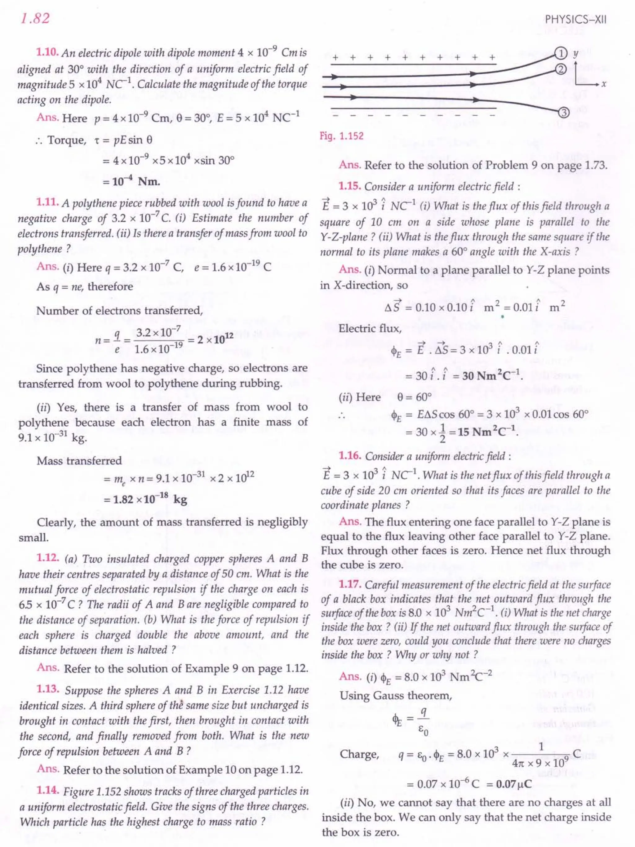
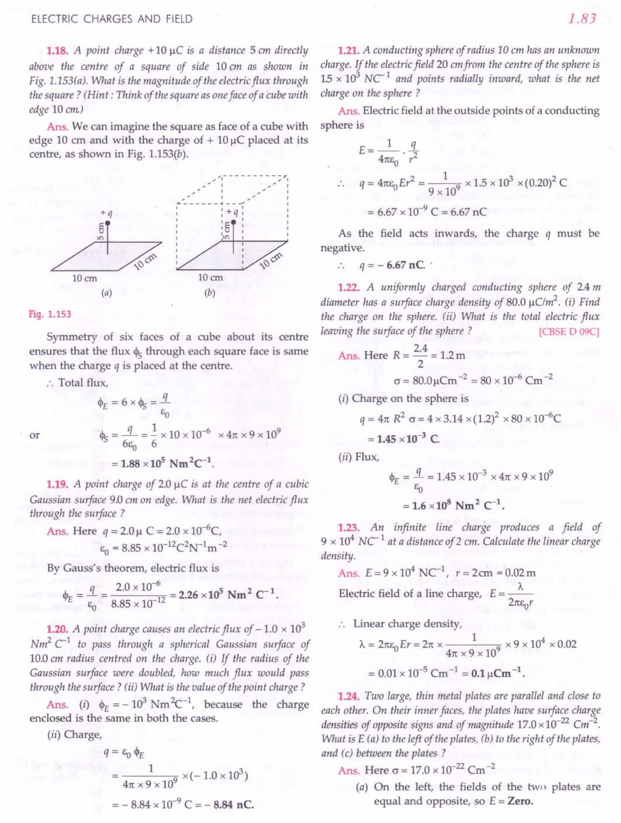
![1.84
(b) On the right, the fields of the two plates are
equal and opposite, so E = Zero.
(c) Between the plates, the fields due to both
plates are in same direction. So the resultant
field is
E = ~ + ~ = ~ = 17 x 10-22
x 41t x 9 x 109
2f:O 2EO EO
= 19.2 x 10⁻¹⁰
NC-1
•
1.25. An oil drop of 12 excess electrons is held stationary
under a constant electric field of255 x 104
Vm-1
in Millikan's
oil drop experiment. The density of the oil is
1.26 g cm-3. Estimate the radius of the drop. ( g = 9.81 ms-2
;
e = 160 x 10- 19 C)
Ans. Force on the oil drop due to electric field
= qE= neE
Weight of oil drop
= mg = volume xdensity xg = ~ 1t r3pg
3
The field E must act vertically
downward so that the negatively
charged oil drop experiences an
upward force and balances the weight
of the drop.
When the drop is held stationary,
mg
Fig. 1.154
or
Weight of oil drop
= Force on the oil drop due to electric field
4 r = [ 3neE]1/3
- 1tr3 pg = neE ..
3 41tpg
Now n = 12, e = 1.6 x 10⁻¹⁹ C,
E = 2.55 x 10⁴
Vm-1, g = 9.81 ms-2
p = 1.26 g em-3 = 1.26 x 10³ kg m-3
r = [3 x 12 x 1.6 x 10-
19
x 2.55 x 104 ]1/3
.. 4 x 3.14 x 1.26 x 103 x 9.81
= [ 9 x 16 x 255 x 10_15]1/3
314 x 126 x 981
= (9.46 x 10⁻⁴)1/3 x 10-5
= 0.0981 x 10⁻⁵ m = 9.81 x 10⁻⁴ mm.
1.26. Which among the curves shown in Fig. 1.155, cannot
possibly represent electrostatic field lines?
Ans. Only Fig. 1.155(c) is right and the remaining
figures cannot represent the electrostatic field lines.
Figure 1.155(a) is wrong because field lines must be
normal to a conductor.
Figure 1.155(b) is wrong because lines of force cannot
start from a negative charge.
PHYSICS-XII
(b)
(c)
(d) (e)
Fig. 1.155
Figure 1.155(c) is right because it satisfies all the
properties of lines of force.
Figure 1.155(d) is wrong because lines of force cannot
intersect each other.
Figure 1.155(e) is wrong because electrostatic field
lines cannot form closed loops.
1.27. In a certain region of space, electric field is along the
Z-direction throughout. The magnitude of electric field is,
however, not constant but increases uniformly along the
positive Z-direction at the rate of 105
NC1m-1. What are the
force and torque experienced by a system having a total dipole
moment equal to 10-
7
C m in the negative Z-direction ?
Ans. The situation is shown in Fig. 1.156.
As the electric field changes uniformly in the positive
Z-direction, so
BE, = + 105 NC1m-1 BEx = 0 a~ = 0
Bz ' ax ' By
As the system has a total dipole moment in the
negative Z-direction, so
pz = - 10- 7 Cm, Px = 0, Py = 0](https://image.slidesharecdn.com/slaroraclass12thphysicsbyrockytrickster-250318042948-c8b51a5a/75/SL-ARORA-CLASS-12TH-PHYSICS-BY-ROCKY-TRICKSTER-pdf-72-2048.jpg)
![ELECTRIC CHARGES AND FIELD
z
x
+q
-q
~P
.J--------y
Fig. 1.156
In a non-uniform electric field, the force on the dipole
will be
8E 8E 8rc
F=p _x+p _Y+p _'""'z_'
x8x Yay z8z
= 0 + 0 - 10-7
x 105
= -10-2
N
The negative sign shows that the force on the dipole
acts in the negative Z-direction.
As the dipole moment p acts in the negative
Z-direction while the electric field E acts in the positive
Z-direction, so e = 180°.
Torque, 't = pE sin 180° = pE x 0 = O.
1.28. (i) A conductor A with a cavity [Fig. 1.157(a)] is
given a charge Q. Show that the entire charge must appear on
the outer surface of the conductor.
(ii) Another conductor B with charge q is inserted into
the cavity keeping B insulated from A Show that the total
charge on the outside surface of A is Q+ q [Fig. 1.157(b)].
(iii) A sensitive instrument is to be shielded from the strong
electrostatic fields in its environment. Suggest a possible way.
Q Q+q
(a) (b)
Fig. 1.157
Ans, (i) Refer answer to Q.25(6) on page 2.25.
(ii) Consider a Gaussian surface inside the conductor
but quite close to the cavity.
Inside the conductor, E = O.
1.85
Fig. 1.158
By Gauss's theorem,
J.. _! --"E d--"S
_ Total charge _
'i'E-r' - -0
EO
i.e., the total charge enclosed by the Gaussian surface must
be zero. This requires a charge of - q units to be induced
on inner surface of conductor A. But an equal and
opposite charge of + q units must appear on outer surface
A so that charge on the surface of A is Q + q.
Hence the total charge on the surface of A is Q + q.
(iii) The instrument should be enclosed in a metallic
case. This will provide an electrostatic shielding to the
instrument.
1.29. A hollow charged conductor has a tiny hole cut into its
surface. Show that the electric field in the hole is ~ ~, where ~
2Eo
is the unit vector in the outward normal direction, and (J is the
surface charge density near the hole.
Ans. Consider the charged conductor with the hole
filled up, as shown by shaded portion in Fig. 1.159.
Applying Gauss's theorem, we find that field just outside
is ~;; and is zero inside. This field can be viewed as the
EO
superposition of the field f2 due to the filled up hole plus
B
A
Fig. 1.159
the field f1 due to the rest of the charged conductor. Since
inside the conductor the field vanishes, the two fields
must be equal and opposite, i.e.,
...(1)](https://image.slidesharecdn.com/slaroraclass12thphysicsbyrockytrickster-250318042948-c8b51a5a/75/SL-ARORA-CLASS-12TH-PHYSICS-BY-ROCKY-TRICKSTER-pdf-73-2048.jpg)
![1.86
And outside the conductor, the fields are added up :
c
11+E2=-
EO
Adding equations (1) and (2), we get
211 = ~ or 11= ~
EO 2ea
Hence the field due to the rest of the conductor or the
field in the hole is
E=~n
2Eo
where n is a unit vector in the outward normal direction.
1.30. Obtain the formula for the electric field due to a long
thin wire of uniform linear charge density A without using
Gauss's law.
[Hint. Use Coulomb's law directly and evaluate the
necessary integral.]
Ans. Refer to the solution of Example 47 on page 1.37.
1.31. It is now believed that protons and neutrons are
themselves built out of more elementary units called quarks. A
proton and a neutron consists of three quarks each. Two types of
quarks, the so called 'up' quark (denoted by u) of charge + (213) e,
and the 'down' quark (denoted by d) of charge ( -1/3) e, together
with electrons build up ordinary matter. Suggest a possible
quark composition of a proton and neutron.
Ans. Charge on 'up' quark (u) = + ~ e
Charge on 'down' quark (d) = - ~ e
Charge on a proton = e
Charge on a neutron = 0
Let a proton contain x 'up' quarks and (3 - x) 'down'
quarks. Then total charge on a proton is
ux+d(3-x)=e
or '£ex-1e(3-x)=e
3 3
2 x
or -x-1+-=1
3 3
or x = 2 and 3 - x = 3 - 2 = 1
Thus a proton contains 2 'up' quarks and 1 'down'
quark. Its quark composition should be : uud.
Let a neutron contain y 'up' quarks and (3 - y) 'down'
quarks. Then total charge on a neutron must be
uy + d (3 - y) = 0
or .£ ey _1 e (3 - y) = 0
3 3
ill ~y-1+~=0
or y = 1 and 3 - Y= 3 - 1= 2
Thus a neutron contains 1 'up' quark and 2 'down'
quarks. Its composition should be : udd.
PHYSICS-XII
...(2)
1.32. (a) Consider an arbitrary electrostatic field configu-
ration. A small test charge is placed at a null point (i.e., where
-->
E = 0) of the configuration. Show that the equilibrium of the
test charge is necessarily unstable.
(b) Verify this result for the simple configuration of two
charges of the same magnitude and sign placed a certain
distance apart.
Ans. (a) We can prove it by contradiction. Suppose the
test charge placed at null point be in stable equilibrium.
Since the stable equilibrium requires restoring force in all
directions, therefore, the test charge displaced slightly in
any direction will experience a restoring force towards the
null point. That is, all field lines near the null point should
be directed towards the null point. This indicates that
there is a net inward flux of electric field through a closed
surface around the null point. But, by Gauss's law, the
flux of electric field through a surface enclosing no charge
must be zero. This contradicts our assumption. Hence the
test charge placed at the centre must be necessarily in
unstable equilibrium.
(b) The null point lies on the midpoint of the line
joining the two charges. If the test charge is displaced
slightly on either side of the null point along this line, it
will experience a restoring force. But if it is displaced
normal to this line, the net force takes it away from the
null point. That is, no restoring force acts in the normal
direction. But stable equilibrium demands restoring force
in all directions, hence test charge placed at null point will
not be in stable equilibrium.
1.33. A particle of mass m and charge ( - o) enters the region
between the two charged plates initially moving along x-axis
with speed Vx (like particle 1 in Fig. 1.152). The length of plate is
Land a uniform electric field Eis maintained between the plates.
Show that the vertical deflection of the particle at the far edge of
the plate is qEL2
/ (2m v;).
Compare this motion with motion of a projectile in
gravitational field.
Ans. The motion of the charge - q in the region of the
electric field Ebetween the two charged plates is shown in
Fig. 1.160.
Fig. 1.160](https://image.slidesharecdn.com/slaroraclass12thphysicsbyrockytrickster-250318042948-c8b51a5a/75/SL-ARORA-CLASS-12TH-PHYSICS-BY-ROCKY-TRICKSTER-pdf-74-2048.jpg)
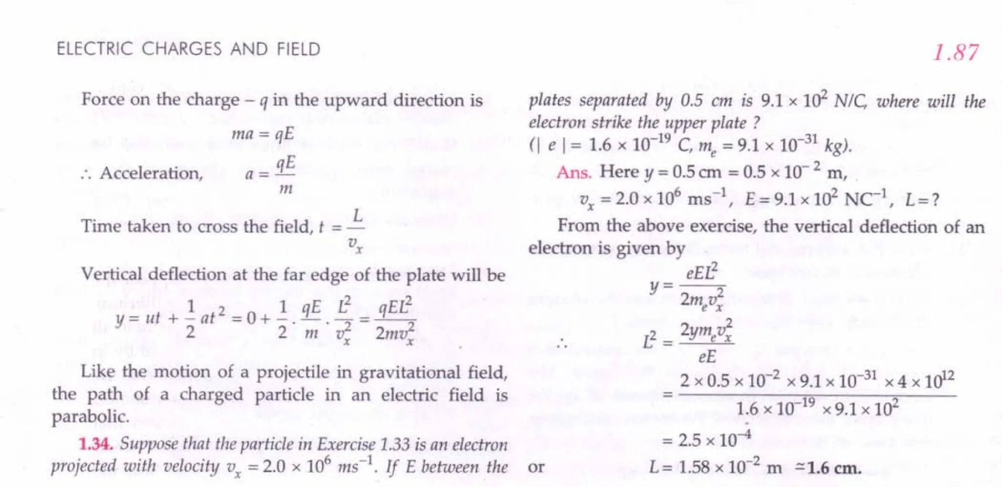
![Text Based Exercises
r/+YPE A : VERY SHORT ANSWER QU ESTIONS (1 mark each)
1. What is the cause of charging a body?
2. An ebonite rod is rubbed with wool or fur. What
type of charges do they acquire? [Haryana 93]
3. A glass rod is rubbed with silk. What type of
charges do they acquire? [CBSEOD 90]
4. Why does an ebonite rod get negatively charged on
rubbing with wool ?
5. Consider three charged bodies P, Q and R If P and
Q repel each other and P attracts R, what is the
nature of the force between Q and R?
6. A positively charged glass rod is brought near an
uncharged pith ball pendulum. What happens to
the pith ball ?
7. When a polythene piece is rubbed with wool, it
acquires negative charge. Is there transfer of mass
from wool to polythene ?
8. Is the force acting between two point electric
charges ql and q2 kept at some distance in air,
attractive or repulsive when:
(i) ql q2 > 0 (ii) ql q2 < 0 ? [CBSE03,07]
9. Name any two basic properties of electric charges.
[CBSED 95C; Punjab 05C]
10. What do you understand by quantisation of
electric charges? [Punjab07, lOC; CBSEOD 92]
11. What is the cause of quantisation of electric
charge? [Punjab lOC]
12. What do you mean by additivity of electric charge?
13. What do you mean by conservation of electric charge?
14. Is the total charge of the universe conserved?
15. A glass rod, when rubbed with silk cloth, acquires a
charge of 1.6 x 10⁻¹³
C What is the charge on silk
cloth ? [CBSED 91 ; Himachal 99; Haryana 99]
16. Two insulated charged copper spheres A and B of
identical size have the charges qA and q B respec-
tively. A third sphere C of the same size but
uncharged is brought in contact with the first and
then with the second and finally removed from both.
What are the new charges on A and B?[CBSEF 11]
17. What is the least possible value of charge?
[Haryana 02]
18. State Coulomb's law of force between charges at
rest. Express the same in SI units.
[CBSEOD 94 ; ISCE93; Haryana 02]
19. In Coulomb's law, F = k ql~2 , what are the factors
r
on which the proportionality constant k depends?
[Himachal 02 ; CPMT93]
20. Name and define the SI unit of charge.
[Punjab 09C,11]
21. In the relation F = k ql ~2 , what is the value of k in
r
free space? [Haryana 02]](https://image.slidesharecdn.com/slaroraclass12thphysicsbyrockytrickster-250318042948-c8b51a5a/75/SL-ARORA-CLASS-12TH-PHYSICS-BY-ROCKY-TRICKSTER-pdf-76-2048.jpg)
!["
1.88
22. Give the SI unit of electrical permittivity of free
space. [Haryana02]
23. Write down the value of absolute permittivity of
free space. [Punjab96]
24. Deduce the dimensional formula for the propor-
tionality constant k in Coulomb's law.
25. Write the dimensional formula for the permittivity
constant EO of free space.
26. What is the force of repulsion between two charges
of 1 C each, kept 1 m apart in vacuum ?
27. Two point charges ''II' and 'q2' are placed at a
distance "d' apart as shown in the figure. The
electric field intensity is zero at a point' P' on the
line joining them as shown. Write two conclusions
that you can draw from this. [CBSE
D 14C]
•••• --- d ---....,._ •........• p
ql q2
28. Define dielectric constant of a medium in terms of
force between electric charges.
[CBSE
D 05llC; F 10; Punjab11]
29. In a medium the force of attraction between two
point electric charges, distance d apart, is F. What
distance apart should these be kept in the same
medium so that the force between them becomes
3 F ? [CBSE
OD98]
30. The force between two charges placed in vacuum is
F. What happens to the force if the two charges are
dipped in kerosene oil of dielectric constant, K = 2?
31. State the superposition principle for electrostatic
force on a charge due to a number of charges.
[NCERT;Haryana01]
32. A force F is acting between two point charges 'q1
and q2' If a third charge q3 is placed quite close to Q2'
what happens to the force between Q1 and Q2 ?
33. How many electrons are present in 1 coulomb of
charge ? [Himachal92; Punjab99]
34. Define volume charge density at a point. Write its
SI unit.
35. Define surface charge density at a point. Write its SI
unit.
36. Defineline charge density at a point. Write its SIunit.
37. Define electric field at a point.
[CBSE
OD95; Punjab2000]
38. Is electric field intensity a scalar or vector quantity ?
Give its SI unit. [CBSE
D 99C]
39. Write the dimensional formula of electric field.
40. Name the physical quantity whose SI unit is
newton coulomb-1. [CBSE
D 98]
41. Draw the pattern of electric field around a point
charge (i) Q > 0 and (ii) Q < O. [CBSE
095, 95C]
PHYSICS-XII
42. Sketch the lines of force due to two equal positive
charges placed near each other. [CBSE
D 96C,03]
43. Sketch the lines of force of a + ve point charge
placed near a -ve point charge of the same
magnitude. [CBSE
D 96C]
44. Draw the lines of force of an electric dipole.
[CBSE
OD95C]
45. Two point charges Q1 and Q2 placed a distance d
apart are such that there is no point where the field
vanishes. What can be concluded from this ?
46. A proton is placed in a uniform electric field
directed along the positive x-axis. In which
direction will it tend to move? [CBSE
D llC]
47. What is an electric dipole? [CBSE
OD08,11]
48. Define electric dipole moment. Write its SI unit.
[CBSE
OD08,11; F 13]
49. Is electric dipole moment a scalar or vector
quantity? [CBSE
06C; F 13]
50. What is a point (ideal) dipole? Give example.
51. How much is the dipole moment of non-polar
molecule?
52. An electric dipole is placed in a uniform electric
field. What is the net force acting on it ?
[CBSE
D 92C; F 94C]
53. When is the torque on a dipole in a field maximum ?
54. What is the effect of torque on a dipole in an electric
field?
55. When does an electric dipole placed in a
non-uniform electric field experience a zero torque
but non-zero force?
56. What is the nature of symmetry of dipole field?
57. Will an electric dipole have translational motion
when placed in a non-uniform electric field? Give
reason for your answer.
58. Does the torque exerted on a dipole in a
non-uniform field depend on the orientation of the
dipole with respect to the field?
59. What is the charge of a dipole? [CBSE
D 10C]
60. Under what condition will a charged circular loop
behave like a point charge in respect of its electric
field?
61. Define electric flux. [Punjab2000,01; CBSE
D 13C]
62. Name the principle which is mathematical
equivalent of Coulomb's law and superposition
principle.
63. What is the relation between electric intensity and
flux? [Punjab97,98,99]
64. How is electric flux expressed in terms of surface
integral of the electric field ?
65. State Gauss theorem in electrostatics.
[Punjab02; CBSE
D 08C]](https://image.slidesharecdn.com/slaroraclass12thphysicsbyrockytrickster-250318042948-c8b51a5a/75/SL-ARORA-CLASS-12TH-PHYSICS-BY-ROCKY-TRICKSTER-pdf-77-2048.jpg)
![ELECTRIC CHARGES AND FIELD
66. Is electric flux a scalar or a vector 7
[CBSE Sample Paper 96]
67. Give the 51unit of electric flux 7 [CBSE D 13C]
68. Give the 51 unit of surface integral [f E. is1 of an
5
electric field 7
69. What is the direction of an area vector 7
70. What is a Gaussian surface 7
71. What is the use of Gaussian surface 7
72. How much is the electric flux through a closed
surface due to a charge lying outside the closed
surface 7
73. Two plane sheets of charge densities + (J and - (J are
kept in air as shown in Fig. 1.161. What are the
electric field intensities at points A and B 7
[CBSE D 03C]
---------------------+cr
• B
----------------------cr
Fig. 1.161
74. Two small balls, having equal positive charge q
coulomb are suspended by two insulating strings of
equal length 1metre from a hook fixed to a stand.
The whole set up is taken in a satellite into space
where there is no gravity. What is the angle
between the two strings and the tension in each
string 7 [TIT 86]
An electric dipole of dipole moment 20 x 10-6 Cm is
enclosed by a closed surface. What is the net flux
corning out of the surface 7 [CBSE D 05]
How does the coulomb force between two point
charges depend upon the dielectric constant of the
medium 7 [CBSE OD 05]
77. Two fixed point charges + 4e and + e units are
separated by a distance a. Where should a third
charge q be placed for it to be in equilibrium 7
[CBSEOD 05]
What is the angle between the directions of electric
field at any (i) axial point and (ii) equitorial point
due to an electric dipole 7 [CBSE Sample Paper 08]
75.
76.
78.
Answers
1.89
79. If the radius of the Gaussian surface enclosing a
charge q is halved, how does the electricflux through
the Gaussian surface change 7 [CBSE OD 08]
A dipole, of dipole moment p, is present in a uni-
80.
81.
-->
form electric field E . Write the value of the angle
--> -->
between p and E for which the torque, expe-
rienced by the dipole, is minimum. [CBSE D 09C]
A charge' c( is placed at the centre of a cube. What is
the electric flux passing through the cube 7
[CBSEOD 12]
A charge' c( is placed at the centre of a cube of side I.
What is the electric flux passing through each face
of the cube 7. [CBSE 00 12]
A charge' c( is placed at the centre of a cube of side I.
What is the electric flux passing through two
opposite faces of the cube 7 [CBSE OD 12]
A charge Q I-lC is placed at the centre of a cube.
What is the flux corning out from anyone surface 7
[CBSE F 10]
Charges of magnitudes 2Q and -Q are located at
points (a,a,a) and (4a,a,a). Find the ratio of the
flux of electric field, due to these charges, through
concentric spheres of radii 2a and 8a centered at the
origin. [CBSE Sample Paper 11]
Two charges of magnitudes -3Q and +2Q are
located at points (a,O) and (4a,O) respectively. What
is the electric flux due to these charges through a
sphere of radius Sa with its centre at the origin 7
[CBSE OD 13]
Two concentric spherical shells of radii R and 2R
are given charges Q1
and Q2
respectively. The
surface charge densities on the outer surfaces are
equal. Determine the ratio Q1: Q2. [CBSE F13]
Write the expression for the torque -t acting on a
dipole of dipole moment p placed in an electric
82.
83.
84.
85.
86.
87.
88.
-->
field E.
89.
[CBSE F 15]
What is the electric flux through a cube of side 1 ern
which encloses an electric dipole 7 [CBSE D 15]
•
1. Charging occurs due to the transfer of electrons
from one body to another.
2. The ebonite rod acquires a negative charge and fur
or wool acquires an equal positive charge.
3. The glass rod acquires positive charge and silk
acquires an equal negative charge.
4. This is because electrons in wool are less tightly
bound than electrons in ebonite rod.
5. Attractive.
6. The pith ball is attracted towards the rod, touches it
and then thrown away.](https://image.slidesharecdn.com/slaroraclass12thphysicsbyrockytrickster-250318042948-c8b51a5a/75/SL-ARORA-CLASS-12TH-PHYSICS-BY-ROCKY-TRICKSTER-pdf-78-2048.jpg)
![1.90
7. The polythene piece acquires negative charge due
to transfer of material particles like electrons from
wool to it, so there is a transfer of mass from wool
to polythene.
8. (i) When q1 q2 > 0, the force is repulsive
(ii) When q1 q2 < 0, the force is attractive.
9. Electric charges are (i) quantised, (ii) additive and
(iii) conserved.
10. Quantisation of electric charge means that the total
charge (q) of a body is always an integral multiple of
a basic charge (e) which is the charge on an electron.
Thus q = ne, where n = 0, ± 1,± 2, ± 3, .
11. The basic cause of quantisation of electric charge is
that during rubbing only an integral number of
electrons canbe transferred from one body to another.
12. Additivity of electric charge means that the total
charge on a system is the algebraic sum (taking into
account proper signs) of all individual charges in
the system.
13. Conservation of electric charge means that the total
charge of an isolated system remains unchanged
with time.
14. Yes, charge conservation is a global phenomenon.
15. To conserve charge, the silk cloth acquires negative
charge of 1.6 x 10- 13c.
16. New charge on sphere A,
q' _ qA
A - 2
New charge on sphere B,
, qB+qA/2 2qB+qA
qB = 2 4
17. The least possible value of charge is the magnitude
of the charge on an electron or proton and it is
e = 1.6 x 10- 19C.
18. Refer to point 14 of Glimpses on page 1.100.
19. The proportionality constant k depends on the
nature of the medium between the two charges and
the system of units chosen.
20. The 51 unit of electric charge is coulomb. One
coulomb is that amount of charge which repels an
equal and similar charge with a force of 9 x 10⁹N
when placed in vacuum at a distance of 1 metre
from it.
21. k = 9 x 10⁹Nm2c-2.
22. 51 unit of &0
= C2N-1m -2.
23. Permittivity of free space,
&0= 8.85 x 10⁻¹²C2
· N-1 m -2.
24. [k] = Fr
2
= MLT -:L
2
= [ML3T-4A-2].
M2 (AT)
PHYSICS-XII
25. [&]=_1_.M2= (AT)2 =[M-1L-3T4A2].
o 41tF r2 [MLT 2L2]
26. F = 9 x 10⁹
N.
27. (i) The point charges q1 and q2 must be of opposite
nature or signs.
(ii) The magnitude of charge q1 must be greater
than that of charge q2'
28. The dielectric constant of a medium is the ratio of
the force between two charges placed some
distance apart in vacuum to the force between the
same two charges when they are placed the same
distance apart in the given medium.
1 3F d
2
d' = ~ d.
29. As F oc 2 .. - = -2 or r:
d F d' ~3.
30.
F. F
F. = -.i!!!. = -
kerosene K 2
The principle of superposition states that the total
force on a given charge is the vector sum of the
individual forces exerted on it by all other charges,
the force between two charges being exerted in
such a manner as if all other charges were absent.
-4 -4 -4 -4
F = 1i2 + 1i3 + + fiN
By the superposition principle, the force between
two charges does not depend on the presence of
third charge. Hence the force between q1 and q2
remains equal to F.
q 1C 18
33. n = - = 19 = 6.25 x 10 electrons.
e 1.6 x 10 C
31.
32.
34. The volume charge density (p) at a point is defined
as the charge contained per unit volume around
that point.
p =!!!L
dV
The 51 unit ofp is coulomb per cubic metre (C m -3).
35. The surface charge density (c) at a point is the
charge per unit area around that point
cr= dq .
dS
The 51 unit for cris Cm -2.
36. The line charge density at a point on a line is the
charge per unit length of the line at that point
A= dq
dL
The 51 unit for A is Cm -1.
37. The electric field at a point is defined as the electro-
static force per unit positive charge acting on a
vanishingly small test charge placed at that point.
F
E = lim
qo -40 qo
Mathematically,](https://image.slidesharecdn.com/slaroraclass12thphysicsbyrockytrickster-250318042948-c8b51a5a/75/SL-ARORA-CLASS-12TH-PHYSICS-BY-ROCKY-TRICKSTER-pdf-79-2048.jpg)
![ELECTRIC CHARGES AND FIELD
38. Electric field is a vector quantity. Its direction is
same as that of the force on a unit positive test
charge.
SI unit of electric field = NC1 or Vm.1.
39. [Electric Field]
Force MLy-2
---=---
Charge C
= MLy-2 = [MLT-3A-1].
AT
40. Ne1
is the SI unit of electric field.
41. (i) See Fig. 1.74 on page 1.47 (ii) See Fig. 1.75 on
page 1.47.
42. See Fig. 1.77 on page 1.47.
43. See Fig. 1.76 on page 1.47.
44. See Fig. 1.76 on page 1.47.
45. The point charges % and q2 are equal and opposite.
46. As the proton has a positive charge, it will tend to
move along positive x-axis i.e., along the direction
of the electric field.
47. An electric dipole is a pair of equal and opposite
charges separated by some distance.
48. Electric dipole moment is the product of either
....
charge q and the vector 2 a drawn from the - ve
charge to the + ve charge.
.... ...•
p = q x 2a
Its SI unit is coulomb metre (Cm).
49. Electric dipole moment is a vector quantity.
50. A point dipole is one which has negligibly small
size. In such a dipole, charge q -+ 00 and size 2a -+ 0
in such a way that the product p = q x 2a has a finite
value. Atomic dipoles are point dipoles.
51. Zero.
52. Zero.
53. Torque is maximum when dipole is held perpen-
dicular to the electric field.
54. Torque tends to align the dipole along the direction
of the electric field.
55. When the dipole is placed parallel to the non-
uniform electric field.
56. The dipole field is cylindrically symmetric.
57. Yes. In a non-uniform electric field, an electric
dipole experiences unequal forces at its ends. The
two forces add up to give a resultant force which
gives a translatory motion to the dipole.
58. Yes. In a non-uniform electric field, the field vector
E (;7)changes from point to point, either in magni-
tude or in direction or both. Therefore, the torque
1.91
----+ ---+ ---t ---t -+
r = P x E (r ) for a dipole located at r changes
with the change in orientation of the dipole with
respect to the field.
59. Zero.
60. When the observation point on the axis of the
circular loop lies at a distance much greater than its
radius, the electric field of the circular loop is
similar to that of a point charge.
61. Electric flux over an area in an electric field repre-
sents the total number of electriclines of forcecrossing
this area normally. If the normal drawn to the
.... ....
surface area tJ.S makes an angle 9with the field E,
then the electric flux through this area is
.... ...•
<1>£ = EtJ.S cos 9 = E . tJ.S
62. Gauss's theorem of electrostatics.
63.
....
The relation between electric intensity E and flux
<1>£ is <1>£ = E tJ.S
cos 9
The electric flux <1>£ through any surface, open or
closed, is equal to the surface integral of the electric
.... ....
field E over the surface S,
64.
65.
f
...•...•
<1>£ = E. dS
s
Gauss's theorem states that the flux of electric field
through any closed surface Sis 1/ EO times the total
charge q enclosed by S.
Mathematically,
<1>£ =f E .is =.1..
s EO
Electric flux is a scalar.
SI unit of electric flux = Nm 2C-1
.
SI unit of f E. dS = Nm 2c-1
.
66.
67.
68.
69. The direction of an area vector is along the outward
drawn normal to the surface.
70. An imaginary closed surface enclosing a charge is
called the Gaussian surface of that charge.
71. By a clever choice of Gaussian surface, we can
easily find the electric field produced by certain
charge systems which are otherwise quite difficult
to determine by the application of Coulomb's law
and superposition principle.
72. Zero.
a
73. EA = 0 and EB = - .
Eo
74. As the two balls are in the state of weightlessness,
the strings would become horizontal due to the
force of repulsion.](https://image.slidesharecdn.com/slaroraclass12thphysicsbyrockytrickster-250318042948-c8b51a5a/75/SL-ARORA-CLASS-12TH-PHYSICS-BY-ROCKY-TRICKSTER-pdf-80-2048.jpg)
![1.92
:. Angle between the two strings = 180°
1 q2
Tension in each string = -- -- N
41tSo . (2/)2 .
75. Zero, because the net charge on the dipole is zero.
76F Fvac· F 1
. med = -- I.e., med oc-
K K
,
77. Refer to the solution of Example 13 on page 1.13.
78. (i) At any axial point, E acts in the direction p.
(ii) At any equatorial point, E acts in the opposite
-->
direction of p
Hence the. angle between the directions of the
above two electric fields is 180°.
79. Electric flux (~£ = q / EO) remains unchanged
because the charge enclosed by the Gaussian
surface remains same.
80. Torque experienced by the dipole is minimum
--> -->
when angle between p and E is 0°.
1: = pE sin 0° = O.
PHYSICS-XII
81 A. ..«
. 't'£-
EO
A. -~ ~_~ s.
83. 't'£ - . - .
6 EO 3 EO
84. Flux through each face of the cube,
~ =~. Q IlNm2
C1
E 6 E
o
85. ~('=2a) =~...i=2: 1
~(, = 8a) 2Q- Q
Net charge enclosed
86. ~£ = -----'''-------
EO
-3Q+2Q Q
EO EO
87. q = 41tR2~ = 1 : 4.
Q2
41t(2R) cr'
--> --> -->
88; 1: = P x E
89. Zero, because the net charge on the dipole is zero.
"YPE B : SHORT ANSWER QUESTIONS (2 or 3 marks each)
1. What is frictional electricity? Briefly describe the
electronic theory of frictional electricity.
2. What is electric charge ? Is it a scalar or vector ?
Name its SI unit.
3. How will you show experimentally that there are
only two kinds pf electric charges?
4. Define electrostatic induction. Briefly explain how
an insulated metal sphere can be positively charged
by induction.
5. What is meant by quantization of electric charge?
What is its cause? [Haryana2000; Punjab01]
6. Give six properties of electric charges. [Punjab99C]
7. State the law of conservation of charge. Give two
examples to illustrate it.
[Himachal96 ; Haryana98, 2000 ; Punjab06C, 10C]
8. How does the speed of an electrically charged
particle affects its (i) mass and (ii) charge?
[CBSE D 93]
9. State Coulomb's law of force between two electric
charges and state its limitations. Also define the
SI unit of electric charge. [Haryana96 ; Punjab2003]
10. Write Coulomb's law in vector form. What is the
importance of expressing it in vector form ?
[Haryana91, 95 ; Punjab98C, 2000]
11. Write the vector form of force acting between two
--> -->
charges ql and q2 having 1. and '2 as their position
vectors respectively. [Himachal2000]
12. State Coulomb's law in vector form and prove that
--> -->
F21 = -li2
where letters have their usual meanings.
[Haryana97]
13. Define electric field intensity. What is its SI unit?
What is relation between electric field and force?
[CBSE OD 91]
14. Define electric field at a point. Give its physical
Significance.
15. Derive an expression for electric field intensity at a
point at distance, from a point charge q.
[CBSE OD 94 ; Haryana95, 99]
16. Write an expression for the force exerted on a test
charge by a continuous charge distribution.
17: Define the term electric dipole moment of a dipole.
State its SI unit. [CBSE OD 08, 11]
18. Define electric field intensity and derive an
expression for it at a point on the axial line of a
dipole. Also determine its direction.
[Punjab2000, 01 ; Haryana98, 02 ; CBSE D 92, 95]](https://image.slidesharecdn.com/slaroraclass12thphysicsbyrockytrickster-250318042948-c8b51a5a/75/SL-ARORA-CLASS-12TH-PHYSICS-BY-ROCKY-TRICKSTER-pdf-81-2048.jpg)
![ELECTRIC CHARGES AND FIELD
19. Define the term 'electric dipole moment'. Is it a
scalar or vector ?
Deduce an expression for the electric field at a
point on the equatorial plane of an electric dipole
of length 2a. [ Haryana 02 ; CBSE F 09 ; OD 13]
20. Define electric field intensity. Write its SI unit.
Write the magnitude and direction of electric field
intensity due to an electric dipole of length 2a at the
midpoint of the line joining the two charges.
[CBSE OD 05]
21. What is an electric dipole? Derive an expression
for the torque acting on an electric dipole, when held
in a uniform electric field. Hence define the dipole
moment. [Haryana 01, 02 ; CBSE D 08 ; OD 03C]
22. Define the term electric dipole moment. Give its
unit. Derive an expression for the maximum torque
acting on an electric dipole, when held ill a uniform
electric field. [CBSE D 02]
23. An electric dipole is placed in uniform external /
-+
electric field E . Show that the torque on the dipole
-+ -+ -+
is given by 't = P x E
where p is the dipole moment of the dipole. What
is the net force experienced by the dipole? Identify
two pairs of perpendicular vectors in the
expression. [CBSE DISC]
24. Draw a labelled diagram showing an electric dipole
-+
making an angle e with a uniform electric field E .
Derive an expression for the torque experienced by
the dipole. [rSCE 95; CBSE OD 14]
25. An elecfric dipole is held in a uniform electric field.
(i) Using suitable diagram, show that it does not
undergo any translatory motion, and
(ii) Derive an expression for the torque acting on it
and specify its direction. When is this torque
maximum ? [CBSE DOS, 08]
26. In a non-uniform electric field, is there any torque or
force acting on a dipole held parallel or antiparallel
to the field. Ifyes, show them by suitable diagrams.
27. Briefly explain how does a comb run through dry
hair attract small pieces of paper.
28. Define an electric field line. Draw the pattern of the
field lines around a system of two equal positive
charges separated by a small distance.
[CBSE D 03 ; Sample Paper 11]
29. Define electric line of force and give its two
important properties. [CBSE DOS]
30. What do electric lines of force represent? Explain
repulsion between two like charges on their basis.
[Punjab 97C]
1.93
31. Define electric flux. Write its SI unit.
A charge q is enclosed. by a spherical surface of
radius R If the radius is reduced to half, how
would the electric flux through the surface change?
[CBSEOD 09]
32. Prove that 1/ r2
dependence of electric field of a
point charge is consistent with the concept of the
electric field lines.
33. State and prove Gauss's theorem in electrostatics.
[Punjab 03 ; CBSE OD 92C, 95]
34. Using Gauss's theorem, obtain an expression for
the force between two point charges. [CBSE OD 91]
35. State Gauss's theorem and express it mathe-
matically. Using it, derive an expression for the
electric field intensity at a point near a thin infinite
plane sheet of charge density O'Cm-2
. [Punjab 03;
CBSE D 07, 09, 12 ; CBSE OD 01, 04, OS,06C]
36. Using Gauss's law establish that the magnitude of
electric field intenisty, at a point, due to an infinite
plane sheet with uniform charge density a; is
independent of the distance of the field point.
[CBSE Sample Paper 11]
37. Use Gauss's law to derive the expression for the
electric field between two uniformly charged large
parallel sheets with surface charge densities 0' and
-0' respectively. [CBSE OD 09]
38. State Gauss's theorem in electrostatics. Uskg this
theorem, -prove that no electric field exists inside a
hollow charged conducting sphere.
[Punjab 03 ; CBSE D 02! 03 C ; CBSE OD 97]
39. A thin conducting spherical shell.of radius R has
charge Q spread uniformly over its surface. Using
Gauss's law, derive an expression for an electric
field at a point outside the shell. Draw a graph of
electricfield E(r) with distance r from the centre of the
shell for 0::; r::; 00. [CBSE D 04, 08, 09; OD 06C, 07]
40. Using Gauss's law obtain the expression for the
electric field due to a uniformaly charged thin
spherical shell of radius R at a point outside the
shell. Draw a graph showing the variation of electric
field with r, for r> Rand r < R [CBSE D 11]
41. A thin straight infinitely long conducting wire
having charge density A. is enclosed by a cylin-
drical surface of radius r and length I, its axis
coinciding with the length of wire. Find the
expression for the electric flux through the surface
of the cylinder. [CBSE OD 11]
42. State Gauss's theorem in electrostatics. Using this
theorem, derive an expression for the electric field
intensity due to an infinitely long, straight wire of
linear charge density A. Cm - 1.
[CBSE D 04, 08, 09 ; OD OS,06C, 07]](https://image.slidesharecdn.com/slaroraclass12thphysicsbyrockytrickster-250318042948-c8b51a5a/75/SL-ARORA-CLASS-12TH-PHYSICS-BY-ROCKY-TRICKSTER-pdf-82-2048.jpg)
![1.94
Answers
PHYSICS-XII
••
1. Refer to points 2 and 6 of.Glimpses on page 1.99.
2. Refer to point 3 of Glimpses on page 1.99.
3. Refer answer to Q. 5 on page 1.2.
4. Refer answer to Q. 11 on page 1.4 and Q. 13 on
page 1.5.
5. Refer answer to Q. 16 on page 1.6.
6. The properties of electric charges are·as follows :
(i) Like charges repel and unlike charges attract
each other.
(ii) Electric charges are quantized.
(iii) Electric charges are additive.
(iv) Electric charges are conserved.
(v) The magnitude of elementary negative charge
is same as that of elementary positive charge
and is equal to 1.6 x 10⁻¹⁹
C.
(vi) Unlike mass, the electric charge on a body is
not affected by its motion.
7. Refer answer to Q. 18 on page 1.8.
8. Refer answer to Q. 19 on page 1.8.
9. Refer to point 14 of Glimpses and the solution of
Problem 3 on page 1.67.
10. Refer answer to Q. 22 on page 1.10.
11. Refer answer to Q. 22 on page 1.10.
12. Refer answer to Q. 22 on page 1.10.
13. Refer answer to Q. 29 and Q. 30 on page 1.25.
14. Refer answer to Q. 29 and Q. 30 on page 1.25.
15. Refer answer to Q. 31 on page 1.29.
16. Refer answer to Q. 33 on page 1.35.
-> -> ->
Add the forces Fv ' Fs and FL .
17. Refer answer to Q. 48 on page 1.91.
18. Refer answer to Q. 37 on page 1.40.
19. Refer answer to Q. 38 on page 1.40.
20. Refer answer to Q. 29 on page 1.25. At any
equatorial point of a dipole,
-> 1 p"
~a = - 47t EO • (,2 + a2)3/2 p
At the midpoint of the dipole (, = 0), the magnitude
of the field is
1 p
E;.qua = 47t e a3
o
The direction of the field is from +ve to -ve charge.
21. Refer answer to Q. 40 on page 1.41.
22. Refer answer to Q. 40 on page 1.41.
23. Refer answer to Q. 40 on page 1.41.
24. Refer answer to Q. 40 on page 1.41.
25. Refer answer to Q. 40 on page 1.41.
26. Refer answer to Q. 41 on page 1.42.
27. Refer answer to Q. 41 on page 1.42.
28. See Fig. 1.77 on page 1.47.
29. Refer answer to Q. 43 on page 1.45.
30. Refer answer to Q. 44(iv) on page 1.47.
31. Refer to point 33 of Glimpses. If the radius of the
spherical surface is reduced to half, the electric flux
would not change as the charge enclosed remains
the same.
32. Refer answer to Q. 46 on page 1.48.
33. Refer answer to Q. 49 on page 1.49.
34. Refer answer to Q. 51 on page 1.50.
35. Refer answer to Q. 53 on page 1.56.
36. Refer answer to Q. 53 on page 1.56.
37. Refer answer to Q. 55 on page 1.57.
38. Refer answer to Q. 56(c) on page 1.58.
39. Refer answer to Q. 56(a) on page 1.58 and see
Fig. 1.103.
40. Refer answer to Q. 56(a) on page 1.58 and see
Fig. 1.103.
41. Refer for answer to Q. 52 on page 1.56.
42. Refer answer to Q. 52 on page 1.56.
rJlTYPE C : LONG ANSWER QU ESTIONS (5 marks each)
1. State the principle of superposition and use it to
obtain the expression for the total force exerted on a
point charge due to an assembly of (N - 1)discrete
point charges. [Haryana 02]
2. Obtain an expression for the electric field at any
point due to a continuous charge distribution.
Hence extend it for the electric field of a general
source charge distribution.
3. (a) Consider a system of ncharges Ql,Q2, ... ,qn with
.. ->->-> -> I
position vectors 1."2' '3' ..·,'n re ative to
some origin '0'. Deduce the expression for the
->
net electric field E at a point P with position
vector ~,due to this system of charges.](https://image.slidesharecdn.com/slaroraclass12thphysicsbyrockytrickster-250318042948-c8b51a5a/75/SL-ARORA-CLASS-12TH-PHYSICS-BY-ROCKY-TRICKSTER-pdf-83-2048.jpg)
![ELECTRIC CHARGES AND FIELD
(b) Find the resultant electric field due to an
electric dipole of dipole moment 2aq, (2a being
the separation between the charges ± q) at a
- point distant 'x' on its equator. [CBSE F 15]
4. A dipole is made up of two charges + q and -q
separated by a distance 2a. Derive an expression for
~
the electricfield Ee due to this dipole at a point distant r
from the centre of the dipole on the equatorial plane.
--->
Draw the shape of the graph, between IEel and r
when r » a.If this dipole were to be put in a uniform
~
external electric field E,obtain an expression for the
torque acting on the dipole. [CBSE SP 15]
5. (a) An electric dipole of dipole moment p consists
of point charges +q and -q separated by a
distance 2a apart. Deduce the expression for
--->
the electric field E due to the dipole at a
distance x from the centre of the dipole on its
--->
axial line in terms of the dipole moment p.
Hence show that in the limit x » a,
E~2p/(41tEox3). y
(b) Given the electric
field in the region
---> A
E = 2xi, find the net
electric flux through
the cube and the z
charge enclosed by it.
[CBSE D 15]
6. (a) State the theorem which relates total charge
enclosed within a closed surface and the
electric flux passing through it. Prove it for a
single point charge.
(b) An 'atom' was earlier assumed to be a sphere
of radius a having a positively charged point
nucleus of charge + Ze at its centre. This nucleus
was believed to be surrounded by a uniform
density of negative charge that made the atom
neutral as a whole. Use this theorem to find the
electric field of this 'atom' at a distance r(r < a)
from the centre of the atom. [CBSE SP 15]
7. (a) Define electric flux. Write its SI units.
Fig. 1.162
Answers
1.95
(b) Using Gauss's law, prove that the electricfield at
a point due to a uniformly charged infinite plane
sheet is independent of the distance from it.
(c) How is the field directed if (i) the sheet is
positively charged, (ii) negatively charged?
[CBSE D 12]
8. State Gauss's law in electrostatics. Using this
theorem, show mathematically that for any point
outside the shell, the field due to uniformly charged
thin spherical shell is the same as if entire charge
of the shell is concentrated at the centre. Why do
you expect the electric field inside the shell to be zero
according to this theorem ? [CBSE D 92; OD06]
9. Using Gauss' law, deduce the expression for the
electric field due to a uniformly charged spherical
conducting shell of radius R at a point (i) outside
and (ii) inside the shell.
Plot a graph showing variation of electric field as a
function of r > R and r < R (r being the distance
from the centre of the shell). [CBSE OD 13,13C]
10. (a) Using Gauss' law, derive an expression for the
electric field intensity at any point outside a
uniformly charged thin spherical shell of
radius R and the density (J C / m 2. Draw the
field lines when the charge density of the
sphere is (i) positive, (ii) negative.
(b) A uniformly charged conducting sphere of
2.5 m in diameter has a surface charge density
of 100IlC/ m 2. Calculate the (i) charge on the
sphere (ii) total electric flux passing through
the sphere. [CBSE D 08]
11. (a) Define electric flux. Write its SI unit.
(b) State and explain Gauss's law. Find out the out-
ward flux due to a point charge + q placed at
the centre of a cube of side' a'. Why is it found
to be independent of the size and shape of the
surface enclosing it ? Explain. [CBSE OD 15]
12. (a) Define electric flux. Write its SI unit.
"Gauss's law in electrostatics is true for any
closed surface, no matter what its shape or size
is". Justify this statement with the help of a
suitable example.
(b) Use Gauss's law to prove that the electric field
inside a uniformly charged spherical shell is
zero. [CBSE OD 15]
1. Refer answer to Q. 27 on page 1.19.
2. Refer answer to Q. 34 on page 1.35.
3. (a) Refer answer to Q. 32 on page 1.29.
(b) Refer answer to Q. 38 on page 1.40.
•
4. Refer answer to Q. 38 on page 1.40 and Q. 40 on
page 1.41.
1
For r » a, l1,qua ex;r3'](https://image.slidesharecdn.com/slaroraclass12thphysicsbyrockytrickster-250318042948-c8b51a5a/75/SL-ARORA-CLASS-12TH-PHYSICS-BY-ROCKY-TRICKSTER-pdf-84-2048.jpg)
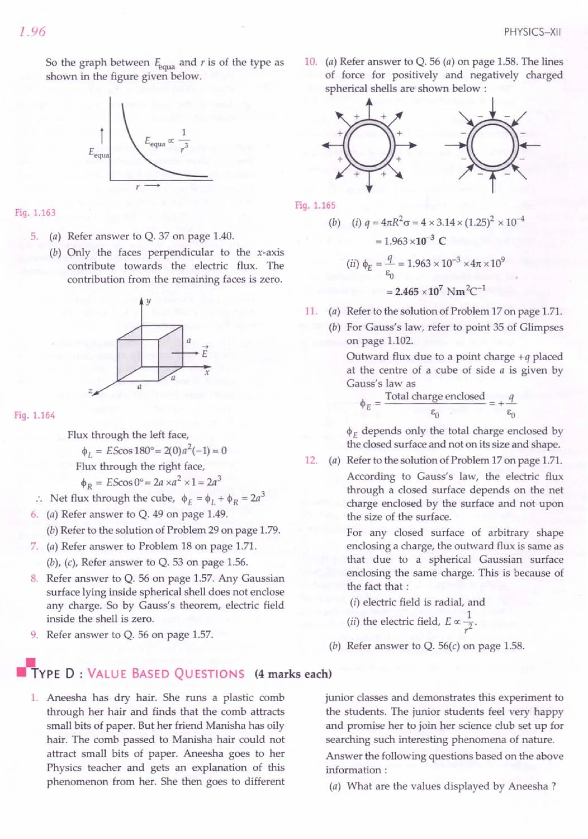
![1.100
14. Coulomb's law. The force of attraction or
repulsion between two stationary point charges
ql and q2 is directly proportional to the product
qlq2 and inversely proportional to the square of
the distance, between them. Mathematically,
F = k qlq2
?
The proportionality constant k depends on the
nature of the medium between the two charges
and the system of units chosen to measure F, ql' q2
and r. For free space and in 51 units,
k =_1_ =9 x 10⁹ Nm2C-2,
41tEo
EO is called permittivity of free space and its
value is 8.854 x 10⁻¹² C2N-1m-2.
Hence Coulomb's law in 51 units may be
expressed as
F __ 1_ q1q2
- 41tE
O
' ?
15. 51 unit of charge is coulomb (C). It is that
amount of charge that repels an equal and
similar charge with a force of 9 x 10⁹
N when
placed in vacuum at a distance of one metre
from it.
16. Permittivity (E). It is the property of a medium
which determines the electric force between
two charges situated in that medium.
17. Dielectric constant or relative permittivity. The
ratio (E / EO) of the permittivity of the given
medium to that of free space is known as
relative permittivity (Er
) or dielectic constant (K)
of the given medium,
E F
E
r
or K = - = -.Yl!f...
EO Frned
The dielectric constant of a medium may be
defined as the ratio of the force between two
charges placed some distance apart in free space
to the force between the same two charges when
they are placed the same distance apart in the
given medium.
Coulomb's law for any medium other than
vacuum can be written as
F _ 1 qlq2 __ 1_ q1q2 _ Fvac
rned - 41tE ----; - 41tEOK ? - K
18. Electrostatic force vs. gravitational force.
Electrostatic forces are much stronger than
PHYSICS-XII
gravitational forces. The ratio of the electric
force and gravitational force between a proton
and an electron is
Fe =~-:::'227x 1039
FG Gmpme
19. Principle of superposition of electrostatic forces.
When a number of charges are interacting, the
total force on a given charge is the vector sum of
the forces exerted on it due to all other charges.
The force between two charges is not affected
by the presence of other charges. The total force
on charge ql due to the charges q2' q3' , qN
will be
~ ~
Fl = F12 +
.x:
41tEo
~ ~
FI3 + , + FIN
N
L
i= 2
qi (ii - r;)
I ~ ~13
'1 - 'i
~ ~
" 1:-r
where 1:. = 1 I
11 ~ ~
l'i - 'i I
= a unit vector pointing from qi to ql'
20. Electric field. An electric field is said to exist at a
point, if a force of electrical origin is exerted
on a stationary charge placed at that point.
Quantitatively, it is defined as the electrostatic
force per unit test charge acting on 'a
vanishingly small positive test charge placed at
the given point. Mathematically,
~
E == lim ~
qo~ a qo
Electric field is a vector quantity whose
direction is same as that of the force exerted on a
positive test charge.
21. Units and dimensions of electric field. The 51
unit of electric field is newton per coulomb
(NC-1
) or volt per metre (Vm-1
). The
dimensions of electric field are
[E] = Force = MLr
2
Charge C
= MLr
2
= [MLr3A-1]
AT](https://image.slidesharecdn.com/slaroraclass12thphysicsbyrockytrickster-250318042948-c8b51a5a/75/SL-ARORA-CLASS-12TH-PHYSICS-BY-ROCKY-TRICKSTER-pdf-88-2048.jpg)
![ELECTRIC CHARGES AND FIELD (Competition Section)
22. Electric field due to a point charge. The electric
field of a point charge q at distance r from it is
given by
1 q
E=-- -
471: EO . r2
If q is positive, E points radially outwards and if
q is negative, E points radially inwards. This
field is spherically symmetric.
23. Electric field due to a system of point charges :
Superposition principle for electric fields. The
principle states that the electric field at any
point due to a group of point charges is equal to
the vector sum of the electric fields produced by
each charge individually at that point, when all
other charges are assumed to be absent.
N
L
i= 1
qi ct -1;)
1 r -1; 1
3
24. Continuous charge distribution. When the
charge involved is much greater than the charge
on an electron, we can ignore its quantum
nature and assume that the charge is distributed
in a continuous manner. This is known as a
continuous charge distribution.
Volume charge density, p =!!i Cm-3
dV
Surface charge density, c = dq Cm-2
dS
Linear charge density, A. = dq Cm-1
dL
25. Electrostatic force and field due to a continuous
charge distribution. The total force on a charge
qo due to a continuous charge distribution is
given by
~
~ F
E = cont
cont q
. 0
= _1_ [f £.. ~dV + f ~ ~dS + fL ~ ~dL 1
471:Eo v? 5 r: r:
1.101
26. Electric field due to a general charge distribution.
It is given by
~ ~ ~
Etota! = Ediscreat + Econt
= _1_ [f q~ ~ + f £..; dV
471:EO i=1 'i v ?
+f ?; dS + f ~; dL]
5 L
27. Electric dipole and dipole moment. An electric
dipole is a pair of equal and opposite charges
+ q and - q separated by some distance 2a. Its
dipole momentis given by
p = Either charge x vector drawn from - q to + q
=qx2ii
Magnitude of dipole moment, p = q x 2a
Dipole moment is a vector quantity having
direction along the dipole axis from - q to + q.lts
SI unit is coulomb metre (em).
28. Electric field at an axial point of a dipole. The
dipole field on the axis at distance r from the
centre is
1 2pr _ 1 2p
Eaxia1 = -- . 2 2 2 - -- . - for r » a.
471:Eo (r-a 471: EO r3
At any axial point, the direction of dipole field is
along the direction of dipole moment p
29. Electric field at an equatorial point of a dipole.
The electric field at a point on the perpendicular
bisector of the dipole at distance r from its
centre is
_ 1 P _ 1 P
Eequa ---. 2 23/2 - --. ::Iforr» a.
471: EO (r" + a ) 471: EO r:
At any equatorial point, the direction of dipole
field is antiparallel to the direction of dipole
~
moment p.
In contrast to 1/? dependence of the electric
field of a point charge, the dipole field has 1/ r3
dependence. Moreover, the electric field due to
a short dipole at a certain distance along the axis
is twice the electric field at the same distance
along the equatorial line.
30. Torque on a dipole in a uniform electric field.
The torque on a dipole of moment p when placed](https://image.slidesharecdn.com/slaroraclass12thphysicsbyrockytrickster-250318042948-c8b51a5a/75/SL-ARORA-CLASS-12TH-PHYSICS-BY-ROCKY-TRICKSTER-pdf-89-2048.jpg)
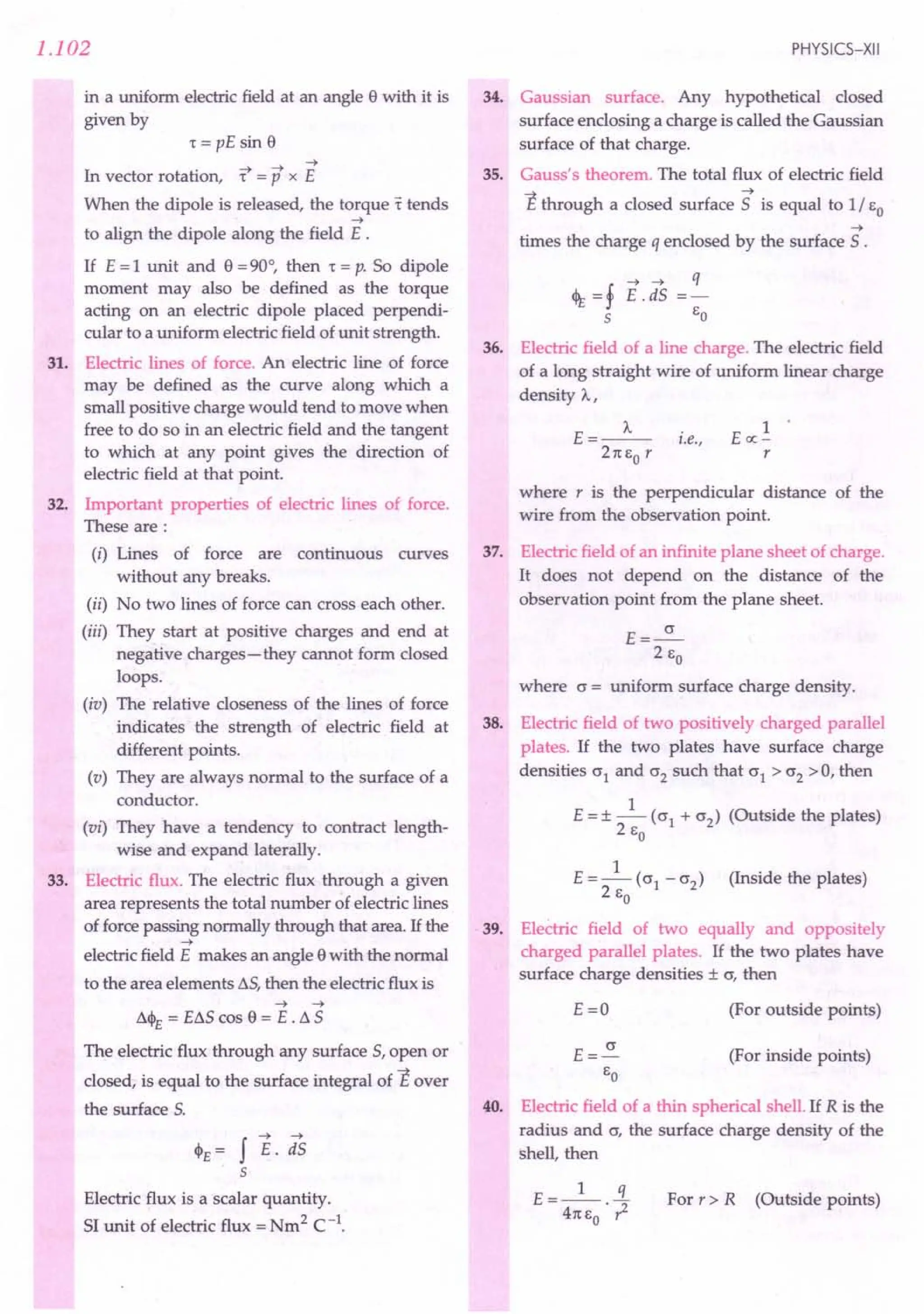
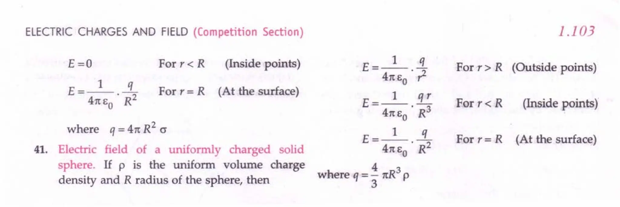
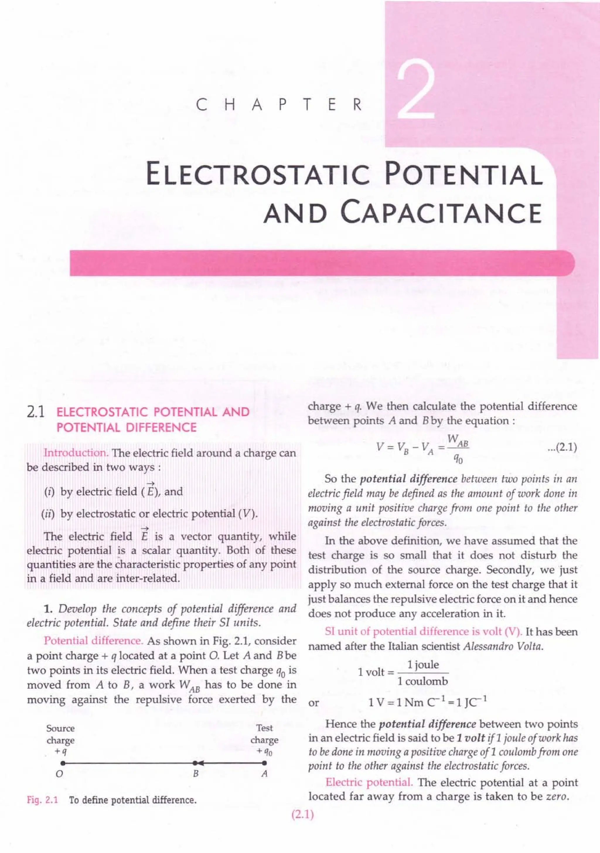
![2.2
In Fig. 2.1,if the point A lies at infinity, then VA = 0, so
that
w
V= VB=-
qo
where W is the amount of work done in moving the
test charge qofrom infinity to the point Band VBrefers
to the potential at point B.
So the electric potential at a point in an electricfield is
the amount of work done in moving a unit positive charge
from infinity to that point against the electrostatic forces.
. . Work done
Electric potential = ----
Charge
SI unit of electric potential is volt (V). The electric
potential at a point in an electricfield is said to be 1 volt if
one joule of work has to be done in moving a positive charge
of 1 coulomb from infinity to that point against the
electrostatic forces.
2.2 ELECTRIC POTENTIAL DUE TO
A POINT CHARGE
2. Derive an expression for the electric potential at a
distance r from a point charge q. What is the nature of
this potential ?
Electric potential due to a point charge. Consider a
positive point charge q placed at the origin O. We wish
to calculate its electric potential at a point P at distance
r from it, as shown in Fig. 2.2. By definition, the electric
potential at point P will be equal to the amount of work
done in bringing a unit positive charge from infinity to
the point P.
q ~ qo F
(9~--------
••
----~.~--~.~--~.
__----oo
o P
'1+--- r -----+t
B A
14 x -----.t~1
Fig. 2.2 Electric potential due to a point charge.
Suppose a test charge qo is placed at point A at
distance x from O. By Coulomb's law, the electrostatic
force acting on charge qois
F __ 1_ qqo
- 4rc EO • x2
~
The force F acts away from the charge q. The small
work done in moving the test charge qo from A to B
~
through small displacement dx against the electro-
static force is
~ ~
dW = F . dx = Fdx cos 1800
= - Fdx
PHYSICS-XII
r r
W = f dW = - f Fdx = - fl. qqo dx
00 co 4rc EO x2
= _~ f X-2 dx =_~ [_.!.]r
4rc EO co 4rc EO X co
_~[~_~] __ 1_ q%
- 4rc EO r 00 - 4rc EO· r .
Hence the work done in moving a unit test charge
from infinity to the point P, or the electric potential at
point Pis
V= W or V=_l_.2.
qo 4rc EO r
Clearly, V cc 1/ r. Thus the electric potential due to a
point charge is spherically symmetric as it depends only
on the distance of the observation point from the
charge and not on the direction of that point with
respect to the point charge. Moreover, we note that the
potential at infinity is zero.
Figure 2.3 shows the variation of electrostatic
potential (V cc 1/r) and the electrostatic field (E o; 1/1)
with distance r from a charge q.
5~-w--r--.---~--r-~--~---r--'---'
4.5
4
3.5
3
t 2.5
t<l
2
:::':
1.5
I
0.5
00 0.5
V=_l_. !!..
41[1:0 r
L5 2 2.5 3 3.5 4 4.5 5
r~
Fig. 2.3 Variation of potential V and field E
with r from a point charge q.
2.3 ELECTRIC POTENTIAL DUE TO A DIPOLE
3. Derive an expression for the potential at a point
along the axial line of a short dipole.
Electric potential at an axial point of a dipole. As
shown in Fig. 2.4, consider an electric dipole consisting
of two point charges - q and + q and separated by
distance 2a. Let P be a point on the axis of the dipole at
a distance r from its centre 0.
-q +q
ee======t:1===:::::::eemummu-l
A 0 B P
I+--- a -~~1"4-- a -----+I
The total work done in moving the charge qo from 14 ~I
infinity to the point P will be Fig. 2.4 Potential at an axial point of a dipole.](https://image.slidesharecdn.com/slaroraclass12thphysicsbyrockytrickster-250318042948-c8b51a5a/75/SL-ARORA-CLASS-12TH-PHYSICS-BY-ROCKY-TRICKSTER-pdf-93-2048.jpg)
![ELECTROSTATIC POTENTIAL AND CAPACITANCE
Electric potential at point P due to the dipole is
1 - q 1 q
V=V +V =--.-+--.-
1 2 41t EO AP 41t EO BP
1 q 1 q
=---.--+--.--
41t~ r+a 41t~ r-a
__ q [_1 __1 ]
41t EO r - a r + a
=_q_[(r+a)-(r-a)]=_l_ qx2a
2 2 . 2 2
41t EO r - a 41t EO r: - a
or V- 1 P
---'--2
41t EO ? -a
[.: p=qx2a]
For a short dipole, a2
< < ?, so V = _1_ E
41t EO . ? .
4. Show mathematically that the potential at a point
on the equatorial line of an electric dipole is zero. or
Electric potential at an equatorial point of a dipole.
As shown in Fig. 2.5, consider an electric dipole
consisting of charges - q and + q and separated by or
distance 2a. Let P be a point on the perpendicular
bisector of the dipole at distance r from its centre O.
p
Fig. 2.5 Potential at an equatorial point of a dipole.
Electric potential at point P due to the dipole is
1 - q 1 q
V=V +V =--.-+--.-
1 2 41t EO AP 41t EO BP
= __ 1_ q +_1_ q =0
41t EO . ~?+ a2 41t EO . ~?+ a2 .
5. Derive an expression for the electric potential at
any general point at distance rfrom the centre of a dipole.
Electric potential at any general point due to a
dipole. Consider an electric dipole consisting of two
point charges - q and + q and separated by distance 2a,
as shown in Fig. 2.6. We wish to determine the potential
at a point P at a distance r from the centre 0, the direc-
~
tion OP making an angle e with dipole moment p.
2.3
Let AP = r1
and BP = r2
. P
Net potential at point P due to the dipole is ,":
" I
V=V1+V2 rl,'" /
=_1_.-q+_1_.!1. "" /r2
41t EO r1 41t EO r2 ,,' /
,rv! I
q [1 1] ~.: "v" :
= 41t EO ~ - ~ ", L e···-. /
A B
[ ]
-q . 0 +q
- 41tQE
o
~2r2 I+-- 2a
--.t
Fig. 2.6
If the point P lies far away from the dipole, then
r1 -'2'" ABcos e =2a cos e and 'lr2"'?
V=-q- 2acose
41t EO . ?
V- 1 pcose
- 41tEo .-?-
--t ~ ~ 1
V- 1 p.r _ 1 p.r
- 41tEo --r-41tEo ~
Here p = q x 2a, is the dipole moment and
" ~
'='/',
~ ~
is a unit vector along the position vector OP = r .
Special Cases
(i) When the point P lies on the axial line of the
dipole, e =0° or 180°, and
1 p
V=+-- -
- 41t EO . ?
i.e., the potential has greatest positive or the
greatest negative value.
(ii) When the point P lies on the equatorial line of the
dipole, e =90°, and V =0, i.e., the potential at
any point on the equatorial line of the dipole is
zero. However, the electric field at such points
is non-zero.
6. Give the contrasting features of electric potential of
a dipole from that due to a single charge.
Differences between electric potentials of a dipole
and a single charge.
1. The potential due to a dipole depends not only
on distance r but also on the angle between the position
~
vector, of the observation point and the dipole moment
~
vector p . The potential due to a single charge depends
only on r.
2. The potential due to a dipoleis cylindrically symmetric
about the dipole axis. If we rotate the observation point](https://image.slidesharecdn.com/slaroraclass12thphysicsbyrockytrickster-250318042948-c8b51a5a/75/SL-ARORA-CLASS-12TH-PHYSICS-BY-ROCKY-TRICKSTER-pdf-94-2048.jpg)
![2.4
P about the dipole axis (keeping rand 8 fixed), the
potential V does not change. The potential due to a
single charge is spherically symmetric.
3. At large distance, the dipole potential falls off as
1/ ?while the potential due to a single charge falls off
as 1/ r.
2.4 ELECTRIC POTENTIAL DUE TO
A SYSTEM OF CHARGES
7. Derive an expression for the electric potential at a
point due to a group of N point charges.
Electric potential due to a group of point charges.
As shown in Fig. 2.7, suppose N point charges
ql' q2' q3' ....., qN lie at distances r1, r2, r3,·····"N from a
point P.
p~~----------~--------------~q4
Fig. 2.7 Potential at a point due to a
system of N point charges.
Electric potential at point P due to charge ql is
V =_1_ !ll
1 .
41t EO r1
Similarly, electric potentials at point P due to other
charges will be
_ 1 q2 _ 1 q3 _ 1 qN
V2 ---.-, V3---·-, ..., VN ---.-
41t EO r2 41tEo r3 41t EO rN
As electric potential is a scalar quantity, so the total
potential at point P will be equal to the algebraic sum
of all the individual potentials, i.e.,
V = VI + V2 + V3 + ...+ VN
=_I_[ql + q2 + q3 + ...+ qN]
41t EO 11 '2 r3 rN
V=_I_ ~ qi
41tEo i=1 ';
~ ~ ~ ~
If r1
, r2
, r3
, ... ,rN
are the position vectors of the N
or
point charges, the electric potential at a point whose
~
position vector is r , would be
V=_I_ ~ qi
41t EO i= 1 1 7_~1
or
PHYSICS-XII
2.5 ELECTRIC POTENTIAL DUE TO A
CONTINUOUS CHARGE DISTRIBUTION
8. Deduce an expression for the potential at a point
due to a continuous charge distribution. Hence write the
expression for the electric potential due to a general source.
Electric potential due to a continuous charge
distribution. We can imagine that a continuous charge
distribution consists of a number of small charge
~ ~
elements located at positions ~. If r is the position
vector of point P, then the electric potential at point P
due to the continuous charge distribution can be
written as
V- 1 f dq
41tE ~ ~
o 1 r - '; 1
When the charge is distributed continuously in a
volume V, dq = P dV, where p is volume charge density.
The potential at point P due to the volume charge
distribution will be
V_I f p dV
v - 41tE ~ ~
oVlr-~1
When the charge is distributed continuously over
an area 5, dq = o dS where o is surface charge density.
V_I f cr dS
5 - 41tE ~ ~
o Sir - '; 1
When the charge is distributed uniformly along a
line L, dq = 'AdL, where A is line charge density.
V_I f AdL
L - 41tE ~ ~
. oLlr-~1
The net potential at the point P due to the conti-
nuous charge distribution will be the algebraic sum of
the above potentials.
V::ont = Vv + Vs + VL
or V =_l_[J ~+J ~+J ~l
cont 4 ---+ ---+- ~ ~ ~-t
11: EO vir - rjl sir -rjl L Ir - rjl
Electric potential due to a general source. The
potential due to a general source charge distribution,
which consists of continuous as well as discrete point
charges, can be written as
V = V::ont + Vdiscrete
V = __1
__ [f p dV + f cr dS
41t EO v 17 - ~ 1 5 17 - ~ 1
+ f A dL " qi 1
~~+L.. ~~
L 1 r - '; 1 All point 1 r - ~ 1
charges](https://image.slidesharecdn.com/slaroraclass12thphysicsbyrockytrickster-250318042948-c8b51a5a/75/SL-ARORA-CLASS-12TH-PHYSICS-BY-ROCKY-TRICKSTER-pdf-95-2048.jpg)
![ELECTROSTATIC POTENTIAL AND CAPACITANCE
2.6 ELECTRIC POTENTIAL DUE TO A
UNIFORMLY CHARGED THIN
SPHERICAL SHELL
9. Write expression for the electric potential due to a
uniformly charged spherical shell at a point (i) outside the
shell, (ii) on the shell and (iii) inside the shell.
Electric potential due to uniformly charged thin
spherical shell. Consider a uniformly charged spherical
shell of radius R and carrying charge q. We wish to
calculate its potential at point P at distance r from its
centre 0, as shown in Fig. 2.8.
p
v V=_l_.~
~ __ 4rc
.•.•
Eo R
Shellwith
charge Q
Fig. 2.8 Potential due to
a spherical shell.
Fig. 2.9 Variation of potential
due to charged shell with distance
T from its centre.
(i) When the point P lies outside the shell. We know
that for a uniformly charged spherical shell, the electric
field outside the shell is as if the entire charge is
concentrated at the centre. Hence electric potential at
an outside point is equal to that of a point charge
located at the centre, which is given by
V=_I_!i [Forr>R]
4m;0 r
(ii) When point P lies on the surface of the shell. Here
r = R.Hence the potential on the surface of the shell is
V=_I_!L [For r= R]
4m;0 R
(iii) When point P lies inside the shell. The electric field
at any point inside the shell is zero. Hence electric
potential due to a uniformly charged spherical shell is
constant everywhere inside the shell and its value is
equal to that on the surface. Thus,
V =_I_!L [For r « R]
4m,0 R
Figure 2.9 shows the variation of the potential V
due to a uniformly charged spherical shell with
distance r measured from the centre of the shell. Note
that V is constant (= q / 4m;oR) from r =0 to r = R along
a horizontal line and thereafter V IX 1/ r for points
outside the shell.
2.5
r>Electric ;::: :~r
~:~'O:::::hil'
pot~ti.~
gradient is a vector quantity.
~ The electric potential near an isolated positive charge is
positive because work has to be done by an external
agent to push a positive charge in, from infinity.
~ The electric potential near an isolated negative charge is
negative because the positive test charge is attracted by
the negative charge.
~ The electric potential due to a charge q at its own
location is not defined - it is infinite.
~ Because of arbitrary choice of the reference point, the
electric potential at a point is arbitrary to within an
additive constant: But it is immaterial because it is the
potential difference between two points which is
physically significant.
~ For defining electric potential at any point, generally a
point far away from the source charges is taken as the
referencepoint. Such a point is assumed to be at infinity.
~ As the electrostatic force is a conservative force, so the
work done in moving a unit positive charge from one
point to another or the potential difference between
two points does not depend on the path along which
the test charge is moved. )
Examples based on
..
Formulae Used
Work done W
1. Potential difference = or V = -
Charge q
2. Electric potential due to a point charge q at
distance r from it,
V = _1_.1
4rc EO r
3. Electric potential at a point due to N point charges,
V = _1_ ~ !iL
4rc EO i = 1 1j
4. Electric potential at a point due to a dipole,
~
V_I pcos e _ 1 P .r
- 4rc EO -r-2- - 4rc EO ~
Units Used
Charge q is in coulomb, distance r in metre, work
done W in joule and potential difference V in volt.
Example 1. lfl00 J of work has to be done in moving an
electric charge of 4Cfrom a place, where potential is -10 V
to another place, where potential is V volt, find the value
ofV.](https://image.slidesharecdn.com/slaroraclass12thphysicsbyrockytrickster-250318042948-c8b51a5a/75/SL-ARORA-CLASS-12TH-PHYSICS-BY-ROCKY-TRICKSTER-pdf-96-2048.jpg)
![ELECTROSTATIC POTENTIAL AND CAPACITANCE
(ii) As potential at any point inside the sphere
= Potential on the surface
:. Potential at a distance of 0.1 em from the centre
= 1.08 x 10⁶
v.
Example 8. Twenty seven drops of same size are charged at
220 Veach. They coalesce to form a bigger drop. Calculate
the potential of the bigger drop. [Punjab 01)
Solution. Let radius of each small drop = r
Radius of large drop = R
Then i1tR3=27xi1tr3
3 3
or R =3r
Potential of each small drop,
V=_l_.!1.
41t EO r
:. Total charge on 27 drops,
Q = 27 q = 27 X 41t EO r V
Potential of large drop,
V' = _1_. Q = _1_ ._27_x_4_1t-,Eo,,-r_V_
41t EO R 41t EO 3r
= 9 V = 9 x 220 = 1980 V.
Example 9. Two charges 3 x 10⁻⁸ C and - 2 x 10⁻⁸ Care
located 15 em apart. At what point on the line joining the
two charges is the electric potential zero? Take the potential
at infinity to be zero. [ CERT)
Solution. As shown in Fig. 2.11, suppose the two
point charges are placed on X-axis with the positive
charge located on the origin 0.
-8 -8
q}=3 x 10 C q2=-2 x 10 C
o-----------+--------~o
o P A
I--- X .,. 0.15 - x ---+l
Fig. 2.11 Zero of electric potential for two charges.
Let the potential be zero at the point P and OP = x.
For x < 0 (i.e., to the left of 0), the potentials of the two
charges cannot add up to zero. Clearly, x must be
positive. If x lies between 0 and A then
VI+V2=0
1 [ql + q2 ] - 0
41t EO x 0.15-x
or 9X10⁹[3X10-
8
_2XlO-
8
]=0
x 0.15-x
3 2
or -----=0
x 0.15-x
which gives x = 0.09 m = 9 em
2.7
The other possibility is that x may also lie on OA
produced, as shown in Fig. 2.12.
-8 -8
q}=3x10 C Q2=-2xlO C
o--------------------~o~------------~I
o A P
I
.....
: 0._15
__
- -_-_-_-x-~'Io-,
--x - 0.15 =1
Fig. 2.12
As VI + V2
=0
.. _1_ [3X 10-
8
_ 2 x 10-
8
] =0
41t EO X x -0.15
which gives x = 0.45 m = 45 em
Thus the electric potential is zero at 9 ern and 45 em
away from the positive charge on the side of the
negative charge.
Example 10. Calculate the electric potential at the centre
of a square of side .J2 m, having charges 100J.lc, - 50 J.lc,
20 J.lc, and - 60 J.lC at the four corners of the square.
[CBSE OD 06C]
Solution. Diagonal of the square
= ~(.J2)2 + (.J2)2 =2 m
Distance of each charge from the centre of the
square is
r = Half diagonal = 1m
., Potential at the centre of the square is
V=_l_[ql + q2 + q3 + q4]
41t EO r r r r
V = 9 x 10⁹ [100 x 10-
6
50 x 10-
6
1 1
20 x 10-6
60 x 10-6
]
+ ----
I 1
= 9 x 109 x 10-6 x 10 = 9 x 10⁴ v.
Example 11. Four charges + q, + q, - q and - q are placed
respectively at the corners A, B, C and D of a square of side
'a' arranged in the given order. Calculate the electric
potential at the centre o. If
E and F are the midpoints
of sides BC and CD respec- a/2
tively, what will be the
work done in carrying a
charge 'e' from 0 to E and a/2
from 0 to F ?
Solution. Let OA =
OB= OC = OD=r.
Fig. 2.13](https://image.slidesharecdn.com/slaroraclass12thphysicsbyrockytrickster-250318042948-c8b51a5a/75/SL-ARORA-CLASS-12TH-PHYSICS-BY-ROCKY-TRICKSTER-pdf-98-2048.jpg)
![2.8
Then the potential at the centre 0 is
V = _1_ [!l. + !l. _ !l. _ !l.] = 0
o 4TCEO
r r r r
Again, the potential at point E is
1 [q q q q]
VE = 4TCE
O
AE + BE - CE - DE =0
[.: AE = DE, BE = CEl
Now, AF = BF =)a
2
+(~r= ~a
.. The potential at point F is
1 [q q q q]
VF = 4TCE
O
AF + BF - CF - DF
-.ss.[_1__ .2..] [.:AF = BF, CF = DFl
4TCEO AF CF
2q [2 2] q (1 )
= 4TCE
O
.Jsa - -;; = TCE
O
a .Js-1
Work done in moving the charge' e' from 0 to Eis
W = e [VE - Vol = e x 0 = 0
Work done in moving the charge 'e' from 0 to F is
W=e[VF -vol=e[-q (~-1)-0]
TCEoa,,5
= TC::aCk-1).
Example 12. A short electric dipole has dipole moment of
4 x 10⁻⁹ Cm Determine the electric potential due to the
dipole at a point distant 0.3 mfrom the centre of the dipole
situated (a) on the axial line (b) on equatorial line and (c) on
a line making an angle of 60° with the dipole axis.
Solution. Here p = 4 x 10⁻⁹
Cm, r =0.3 m.
(a) Potential at a point on the axial line is
1 p 9 x 109 x 4 x 10-9
V=--.-= =400 V.
41tEo ? (0.3)2
(b) Potential at a point on the equatorial line = o.
(c) Potential at a point on a line that makes an angle
of 60° with dipole axis is
V __ 1_ pcosS
- 4TCE
O
• ?
9 x 109
x 4 x 10-9 cos 60°
2 =200 V.
(0.3)
Example 13. Two point charges of +3~C and-3 ~C are
placed 2 x 10⁻³ mapari from each other. Calculate (i) electric
field and electric potential at a distance of 0.6 m from the
PHYSICS-XII
dipole in broad-side-on position (ii) electric field and electric
potential at the same point after rotating the dipole through
90°.
Solution. Dipole moment,
p = q x 21 =3 x 10-6 x 2 x 10-3 =6 x 10⁻⁹Cm
(i) Electric field in broad-side-on position is
E= _1_. E = 9x 10
9
x6x 10-
9
=250 Net
4TC
EO r3 (0.6)3
Electric potential in broad-side-on position, V = O.
(ii) When the dipole is rotated through 90°, the
same point is now in end-on-position with respect to
the dipole.
E=_l_. 2p=500 Net
4TC
EO r3
1 p 9 x 109
x 6 x 10-9
V=--.-= =150V.
4TCE
O
? (0.6l
Example 14. Two charges -q and +q are located at points
A(O,O,-a) and B(O,O,+a) respectively. How much work is
done in moving a test charge from point P(7,O,0) to
Q( -3,0,0) ? [CBSE 0 09)
Solution. Points P and Q are located on the equa-
torial line of the electric dipole and potential of the
dipole at any equatorial point is zero.
:. Work done in moving a test charge qofrom P to Q,
W = qO(VQ- Vp)=qo(O-O)=O.
-q
B(O, 0, a)
Q(-3, 0, 0)
X
P(7, 0, 0)
+q
~--~~------~-------'----.Z
A(O, 0, - a)
y
Fig. 2.14
r-p roblems For Practice
1. The work done in moving a charge of 3 C between
two points is 6 J. What is the potential difference
between the two points? (Ans. 2 V)
2. The electric potential at 0.9 m from a point charge is
+ 50 V. What is the magnitude and sign of the
charge? [CBSE D 95C]
(Ans. 5 x 10- 9 C, positive)](https://image.slidesharecdn.com/slaroraclass12thphysicsbyrockytrickster-250318042948-c8b51a5a/75/SL-ARORA-CLASS-12TH-PHYSICS-BY-ROCKY-TRICKSTER-pdf-99-2048.jpg)
![ELECTROSTATIC POTENTIAL AND CAPACITANCE
3. The electric field at a point due to a point charge is
20 NC-1
and the electric potential at that point is
10 JC-1
. Calculate the distance of the point from the
charge and the magnitude of the charge.
[CBSED 06]
(Ans. 0.5 m, 0.55 x 1O-9
q
4. Two points A and B are located in diametrically
opposite directions of a point charge of + 2 J.lCat
distances 2.0 m and 1.0 m respectively from it.
Determine the potential difference VA - VB'
(Ans. - 9 x 10³
V)
5. A hollow metal sphere is charged with 0.4 J.lCof
charge and has a radius of 0.1 m. Find the potential
(i) at the surface (il) inside the sphere (iil) at a
distance of 0.6 m from the centre. The sphere is
placed in air. (Ans. 36 kV, 36 kV, 6 kV)
6. Two point charges of + 10 J.lC and + 20 J.lC are
placed in free space 2 cm apart. Find the electric
potential at the middle point of the line joining the
two charges. (Ans. 27 MV)
7. Two point charges q and -2q are kept 'd' distance
apart. Find the location of the point relative to
charge 'q' at which potential due to this system of
charges is zero. [CBSEOD 14C]
(Ans. At distance d / 3 from charge q)
8. Two point charges, one of + 100 J.lCand another of
- 400 J.lC,are kept 30 cm apart. Find the points of
zero potential on the line joining the two charges
(assume the potential at infinity to be zero).
(Ans.6 cm from + 100 J.lCcharge)
9. A charge q = + 1J.lCis held at 0 between the points
A and Bsuch that AO = 2 m and 80 = Irn, as shown
in Fig. 2.15(a). Calculate the potential difference
(VA - VB)' What will be the value of the potential
difference (VA - VB) if position of B is changed as
shown in Fig. 2.15(b) ? (Ans. - 4500 V, - 4500 V)
q
• • •
B 1m 0 2m A
(a)
B
1m
q
0 2m A
(b)
Fig. 2.15
10. Two small spheres of radius 'a' each carrying
charges + q and - q are placed at points A and B,
distance'd' apart. Calculate the potential difference
between points A and B. (Ans.2q/4TtEOd)
2.9
11. The sides of rectangle ABCD are 15 cm and 5 ern, as
shown in Fig. 2.16. Point charges of - 5 J.lC and
+ 2J.1Care placed at the vertices Band D respec-
tively. Calculate electric potentials at the vertices A
and C. Also calculate the work done in carrying a
charge of 3 J.lCfrom A to C. (Ans. 2.52 J)
A 0
Fig. 2.16
12. Charges of 2.0 x 10⁻⁶ C and 1.0 x 10⁻⁶
C are placed at
the comers A and B of a square of side 5.0 cm as
shown in Fig. 2.17. How much work will be done in
moving a charge of 1.0 x 1O-6Cfrom C to D against
the electric field? (Ans. 0.053 J)
o 5cm C
,,0:,
A B
Fig. 2.17
13. Calculate the potential at the centre of a square
ABCD of each side .fi m due to charges 2, - 2, - 3
and 6 J.lCat four comers of it. [Haryana 97]
(Ans. 2.7 x 10⁴
V)
14. Charges of + 1.0 x 10⁻¹¹
C, - 2.0 x 10⁻¹¹
C,
+ 1.0 x 10⁻¹¹
C are placed respectively at the comers
B, C and D of a rectangle ABCD. Determine the
potential at the comer A. Given AB = 4 em and
BC= 3cm.
(Ans. 1.65 V)
15. ABCD is a square of side 0.2 m. Charges of 2 x10⁻⁹
,
4 x 10⁻⁹
, 8 x 10⁻⁹
C are placed at the comers A, B
and C respectively. Calculate the work required to
transfer a charge of 2 x 10⁻⁹
C from D to the centre a
of the square. [Kamataka 88]
(Ans. 6.27 x 10- 7 J)
16. Positive charges of 6, 12 and 24 nC are placed at the
three vertices of a square. What charge must be
placed at the fourth vertex so that total potential at
the centre of the square is zero? (Ans. - 42 nq
17. Two equal charges, 2.0 x 10⁻⁷
C each are held fixed
at a separation of 20 cm. A third charge of equal
magnitude is placed midway between the two
charges. It is now moved to a point 20 ern from both
the charges. How much work is done by the electric
field during the process? (Ans. - 3.6 x 10⁻³ J)](https://image.slidesharecdn.com/slaroraclass12thphysicsbyrockytrickster-250318042948-c8b51a5a/75/SL-ARORA-CLASS-12TH-PHYSICS-BY-ROCKY-TRICKSTER-pdf-100-2048.jpg)
![2.10
18. ABC is a right-angled triangle, where AB and BC
are 25 em and 60 em respectively; a metal sphere of
2 em radius charged to a P9tential of 9 x 10⁵
V is
placed at B. Find the amount of work done in
carrying a positive charge of 1 C from C to A.
A (Ans. 0.042 J)
~c
Fig. 2.18
HINTS
w 6J
1. V=-=-=2V.
q 3C
2. As V = _1_}. .. 50 = 9 x 10⁹ x-.!L.
41tEo r 0.9
_ 50 x 0.9 _ 5 lO-9
C
or q----9 - x
9 x 10
As the potential is positive, the charge q must be
positive.
3. Electric field of a point charge,
E= _1_ .!L = 20 NCI
41tEo r2
Electric potential of a point charge,
V = _1_ . .1= 10 JCI
41tEo r
Clearly, distance r = V = 10 = 0.5 m
E 20
Magnitude of charge,
10 x 0.5 -9
q=41tEo' V.r=---9 =0.55x10 C.
9 x 10
4. Here' q=2f,lC=2x10⁻⁶C,rA=2m,rB=lm
V - V = -q-[~_1.]
A B 41tEo r
A
r
B
= 2 x 10-
6
x 9 x 10
9
[~- ~JV
= - 9 x 10³
V.
5. (i) Potential at the surface,
1 q 4 x 10-7
x 9 x 109
V=--.-=-----
41tEO r 0.1
= 36000 V = 36 kV.
(ir) Potential inside a hollow conductor is the same
as on its surface.
(iii) When r = 0.6 m,
9 x 109 x 4 x 10-7
V = = 6000 V = 6 kV.
0.6
PHYSICS-XII
6. V = t'J + V
2
= _1_ [ ql + q2]
41tEO '1 r2
9 [ 10 x 10-6 20 x 10-6]
= 9 x 10 + --:--:- _
0.01 0.01
= 27 x 106
V = 27 MV.
7. Let the point P of zero potential lie at distance x
from the charge q.
q x d -x -2q
o~--~I--~~--------~o
A P B
.. _1_.9 ..+ _1_. (-2q) =0 or.! =_2_ or x =:!..
41tEoX 41tEo(d - x) x d - x 3
8. Suppose the point of zero potential is located at
distance x metre from the charge of + 100 u C, Then
V = _1_ [100 x 10-
6
_ 400 x 10-6] = 0.
41tEo x 0.30 - x
This gives x = 0.06 m = 6 em i.e., the point of zero
potential lies at 6 em from the charge of + 100f,lc.
V V
_ 9 [ 1.0 x 10⁻⁶ 1.0 x 10⁻⁶]
9. A - B - 9 x 10 - ---
2.0 1.0
=-4500V
As potential is a scalar quantity, so change in position
of the charge does not affect the value of potential.
10. VB- VA=_1_.~ __ l_.=.!L-.-3L
41teo d 41tEo d 41teo d
[
2 10-6 5 10-6]
11. VA= 9 x 10⁹ x - x = - 7.8 x 10⁵ V
0.15 0.05
[
2 x 10⁻⁶ 5 x 10⁻⁶]
Ve = 9 x 10⁹ - = 0.6 x 10⁵ V
0.05 0.15
W = q (Ve - VA)= 3.0 x 10⁻⁶(0.6 x 10⁵ + 7.8 x 10⁵)
=2.52 J.
12. V - _1_ [~ + .31...J
e - 41tEo AC BC
9
9 [2.0 x 10- 6 1.0 x 10- 6 ]
= x10 + -----
-Ii x 0.05 0.05
=9000[ 2+.fi]V
.fi x 0.05
V 1 [ql q2J
D = 47tEO AD + BD
. 0:
9 [2.0 x 10⁻⁶ 1.0 x 10⁻⁶]
=9x1 +-;=--
0.05 .fi x 0.05
= 9000 [ 2.fi + 1 ] V
.fi x 0.05](https://image.slidesharecdn.com/slaroraclass12thphysicsbyrockytrickster-250318042948-c8b51a5a/75/SL-ARORA-CLASS-12TH-PHYSICS-BY-ROCKY-TRICKSTER-pdf-101-2048.jpg)
![ELECTROSTATIC POTENTIAL AND CAPACITANCE
W= q(Vo - Vc)
= 1.0 x 10-6 x 9000 [2..fi + 1- 2 - ..fi]
-Ii x 0.05
= 0.053 J.
13. Diagonal of the square = ~(..fi)2 + (..fi)2 = 2 m
Distance of each charge from the centre,
r = Half diagonal = 1 m
:. Potential at the centre of the square is
9 [2 x 10⁻⁶ 2 x 10⁻⁶ 3 x 10⁻⁶ 6 x 10⁻⁶]
V=9x10 -----------+---
1 1 1 1
= 2.7 x 10⁴
V.
14. AC= ~42 + 32 = 5crn = 0.05 m, AD= BC = 0.03 m
1 [ 1.0 x10⁻¹¹
2.0 x 10⁻¹¹
1.0 x 10⁻¹¹
]
V=-- - +----
41teo 0.04 0.05 0.03
=1.65 V.
9 [2 x 10⁻⁹
4 x 10⁻⁹
8 x 10⁻⁹
]
15. V0 = 9 x 10 + + ---
0.2 0.2 Ji 0.2
= 577.26 V
9 [2 x 10⁻⁹
4 x 10-
9
8 x 10⁻⁹
]
V =9xlO + +----r~
o 0.1..fi 0.1..fi 0.1..fi
= 890.82V
W = q [V 0 - VoJ = 2 x 10⁻⁹
[890.82 - 577.26]
= 6.27 x 10⁻⁷
J.
16. Suppose a charge of q nC be placed at the fourth
vertex.
Let length of half diagonal be x metre.
9 [ 6 x 10⁻⁹
12 x 10-9
24 x 10-9
Vo = 9 x 10 + + ---
x x x
q x 10-
9
]
+ =0
x
~ + 12 + 24 + 3.. = 0
x x x x
3..= _ 42
x x
or q = -42 nC.
17. The situation is shown in Fig. 2.19.
" 1 [ 2 x 10⁻⁷ 2 x 1O~7]"
V -V =-- +---
C 0 41tto 0.20' 0.20
1 [2 x 10-
7
2 x 10-
7
]
- 41tto 0.10 + 0.10
= - 1.8 x 10⁻⁴ V
or
or
2.11
c
Fig. 2.19
W = q(Vc - Vo)
= - 2 x 10-7
x 1.8 x 104
= - 3.6 x 10⁻³
J.
18. Potential of the charged sphere is
V=_l_.!1.
41tEO r
.. 9 x 105 = 9 x 10⁹ x -q-
0.02
0.02 2 -6 C
q = 104 = x 10 = 21-1
Potential at A due to charge q is
1 q 9 x 109
x 2 x 10-6
VA
=--.-= V
41tEO r 0.25
or
Potential at C due to charge q is
9 x 109
x 2 x 10-6
Vc= V
0.60
Potential difference between A and C is
VA - Vc = 1.8 x 10⁻³ [_1 1_] V
0.25 0.60
1.8 x 7
= --V = 0.042 V
300
Work done in moving a charge of + 1C from C to A
W = q (VA - Vc) = 1 x 0.042 = 0.042 J.
2.7 RELATION BETWEEN ELECTRIC FIELD
AND POTENTIAL
10. Show that the electric field at any point is equal to
the negative of the potential gradient at that point.
Computing electric field from electric potential. As
shown in Fig. 2.20, consider the electric field due to
charge + q located at the origin O. Let A and Bbe two
adjacent points separated by distance dr. The two
+q
•
a B A
Fig. 2.20 Relation between potential and field.](https://image.slidesharecdn.com/slaroraclass12thphysicsbyrockytrickster-250318042948-c8b51a5a/75/SL-ARORA-CLASS-12TH-PHYSICS-BY-ROCKY-TRICKSTER-pdf-102-2048.jpg)
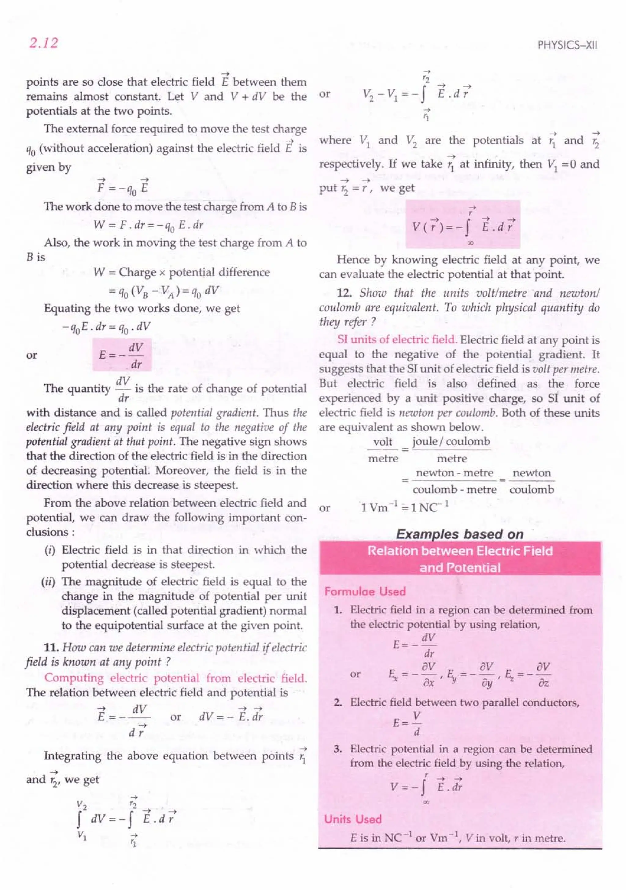
![ELECTROSTATIC POTENTIAL AND CAPACITANCE
Example 15. Find the electric field between two metal
plates 3 mm apart, connected to 12 V battery.
Solution. Electric field,
E ==V == 12 V ==
4 x 10³ Vm-1
d 3 x 10⁻³ m
Example 16. Calculate the voltage needed to balance an oil
drop carrying 10 electrons when located between the plates
of a capacitor which are 5 mmuparitg« 10 ms" 2). The mass
of oil drop is 3 x 10- 16kg.
Solution. q ==
ne ==
10 x 1.6 x 10- 19C
m==3x 10-16 kg, d ==5mm ==5x 10⁻³ m
E== V == V Vm-1
d 5 x 10- 3
For the charged oil drop to remain stationary in
electric field,
qE ==
mg
10 x 1.6 x 10-19 x V 3 ==3x 10-16 x 10
5 x 10-
3 x 10-16 x 10 x 5 x 10-3
V == ==
9.47 V.
10 x 1.6 x 10-19
or
Example 17. An infinite plane sheet of charge densitJj
10- 8 Cm 2 is held in air. In this situation how far apart are
two equipotential surfaces, whose p.d. is 5 V ?
Solution. Electric field of an infinite plane sheet of
charge,
E==~
21:0
If M is the separation between two equipotential
surfaces having potential difference to. V, then
E ==to.V
M
(j to.V
or
21:0 M
M==21:0
to.V ==2xB,B5x 10-12 x 5
(j 10-8
==
B.B5 x 10-3
m ==
8.85 mm.
Example 18. A spark passes in air when the potential
gradient at the surface of a charged conductor is
3 x 10⁶
Vm-1
. What must be the radius of an insulated
metal sphere which can be charged to a potential of 3 x 10⁶
V
before sparking into air ?
Solution. Potential gradient,
dV ==3x 10⁶ Vm-1
dr
dV ==
3 x 10⁶
dr
V ==
3 x 10⁶
r
or
or
2.13
or
But V-==
3 x 10⁶
V
. . 3 x 10⁶
r ==
3 x 10⁶
r ==1m.
Example 19. A uniform electric field E of 300 NC1
is
directed along negative X-axis. A, Band C are three points
in thefield, having x and y coordinates (in metre), as shown
in Fig. 2,21. Find the potential differences to. VBA' to. VCBand
to.VCA
·
y
B (4, 4)
C(-3,4)
.~----~--------~--
A (4, 1)
E'~----~--------~--
------------~o+---------------~~x
Fig. 2.21
Solution. (i) No work is done in moving a unit
positive charge from A to B because the displacement
of the charge is perpendicular to the electric field. Thus
the points A and B are at the same potential.
.. to.VBA==0
(ii) Work is done by the electric field as the positive
~
charge moves from B to C ii.e., in the direction of E).
Thus the point C is at a lower potential than the point R
As E==_to.V
Sx
to.VCB
==
- E f'o.x ==
-300 Ne1 x 7 m
==
- 2100 V.
(iii) Points A and B lie on an equipotential surface.
So VB ==VA
to.VCA
==VC-VA ==VC-VB==to.VCB
==
-2100 V.
Example 20. Three points A, Band C lie in a uniform
electric field (E)of5 x 103
NC1
as shown in thefigure. Find
the potential difference between A and C. [CBSE F 09]
~
,,
5cm',
I
13cm
~E
I
'IC
Fig. 2.22](https://image.slidesharecdn.com/slaroraclass12thphysicsbyrockytrickster-250318042948-c8b51a5a/75/SL-ARORA-CLASS-12TH-PHYSICS-BY-ROCKY-TRICKSTER-pdf-104-2048.jpg)
![2.14
Solution. Points B and C lie on an equipotential
surface, so Vc = VB"
P'D. between A and C = P'D, between A and B
=-Eill
= -Sx 103
NC1
x 4x 10-2
m [.: E = - ~J
= -200 V. [ill = AB = ~S2 _32 = 4 em]
Example 21 . If the potential in the region of space around
the point (-1m,2 m,3 m) is given by
V = (10x2 + Sy2 -3z2
) volt, calculate the three components
of electric field at this point.
Solution. Here x = -1 m, y =2. m, z =3 m
As V = lOx2 + Sl-3z2
av a 2 2 2
E =--=--(10x +Sy -3z)
x ax ax
= -20x =-20 x (-1)=20 Vm-1
.
av a 2 2 2
E =-=--(lOx +Sy -3z )=-10y
Y 8y dy
=-10x2 =-20Vm-1
E =_av =-~(10x2+Sy2-3z2)=6z
Z az dz
= 6 x 3 = 18 Vm -1.
j2)roblems For Practice
1. A uniform electric field of 20 NC-1
exists in the
vertically downward direction. Determine the
increase in the electric potential as one goes up
through a height of 50 cm. (Ans. 10 V)
2. A uniform electric field of 30 NC-1
exists along the
X-axis. Calculate the potential difference VB - VA
between the points A (4 m, 2 m)and B(10 m, 5 m).
(Ans. - 180 V)
----t 1 1'1 1
3. An electric field E = 20 i + 30 j NC - exists in free
space. If the potential at the origin is taken zero,
determine the potential at point (2 m, 2 m).
(Ans. -100 V)
4. The electric field in a region is given by E = ~ I,
x
Write the 51unit for A. Write an expression for the
potential in the region assuming the potential at
infinity to be zero. ( Ans. Nm 3C-1,;:2)
5. Figure 2.23shows some equipotential surfaces. What
can you say about the magnitude and the direction of
the electricfield ?
(Ans. E = ~ Vm-1, radially outward)
r
PHYSICS-XII
30V
20cm:
9
'
"
,
, '
60~~~~
20V
Fig. 2.23
HINTS
1. L'1V = - EL'1 r = - 20 x (-~) = 10 V.
100
2. ~V = - So L'1x = - 30(10 - 4) = -180 V.
3. ~ V = - So L'1 x - E,.L'1 Y = - 20 x 2 - 30 x 2 = -100 V.
4. .: 51unit of electric field = NC-1
:. 51unit of A = NC-1 x m3 = Nm3 C-1
(x,y,z) Ad A
Potential, V = - f -; = -2 .
x 2x
00
5. For the equipotential surface of 60 V,
60 V = kq =--'.:L
r 0.10m
or kq = 60 V x 0.10 m = 6 Vm
E- kq _£ V -1
•. - 2 - 2 m
r r
Clearly, E decreases with r. The direction of electric
field will be radially outward because V decreases
with r.
2.8 EQUIPOTENTIAL SURFACES AND THEIR
PROPERTIES
13. What is an equipotential surface ? Give an
example.
Equipotential surface. Any surface that has same
electric potential at every point on it is called an equipo-
tential surface. The surface may be surface of a body or a
surface in space. For example, as we shall see later on,
the surface of a charged conductor is an equipotential
surface. By joining points of constant potential, we can
draw equipotential surfaces throughout the region in
which an electric field exists.
14. State and prove the important properties of
equipotential surfaces.
Properties of equipotential surfaces: 1. No work is
done in moving a test charge over an equipotential surface.](https://image.slidesharecdn.com/slaroraclass12thphysicsbyrockytrickster-250318042948-c8b51a5a/75/SL-ARORA-CLASS-12TH-PHYSICS-BY-ROCKY-TRICKSTER-pdf-105-2048.jpg)
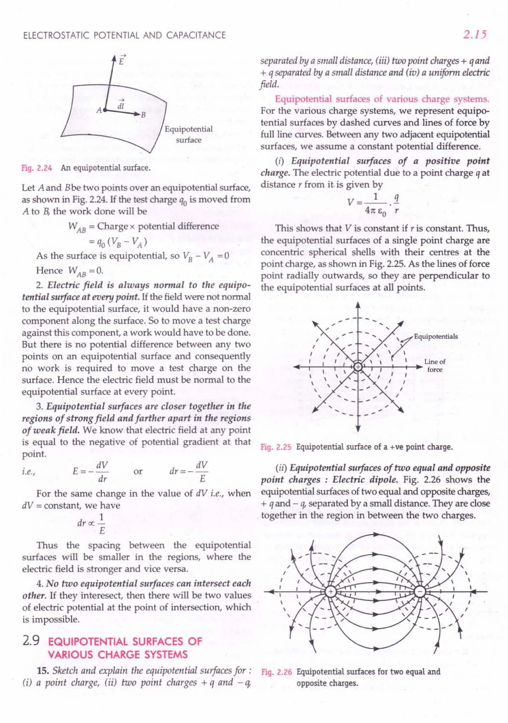
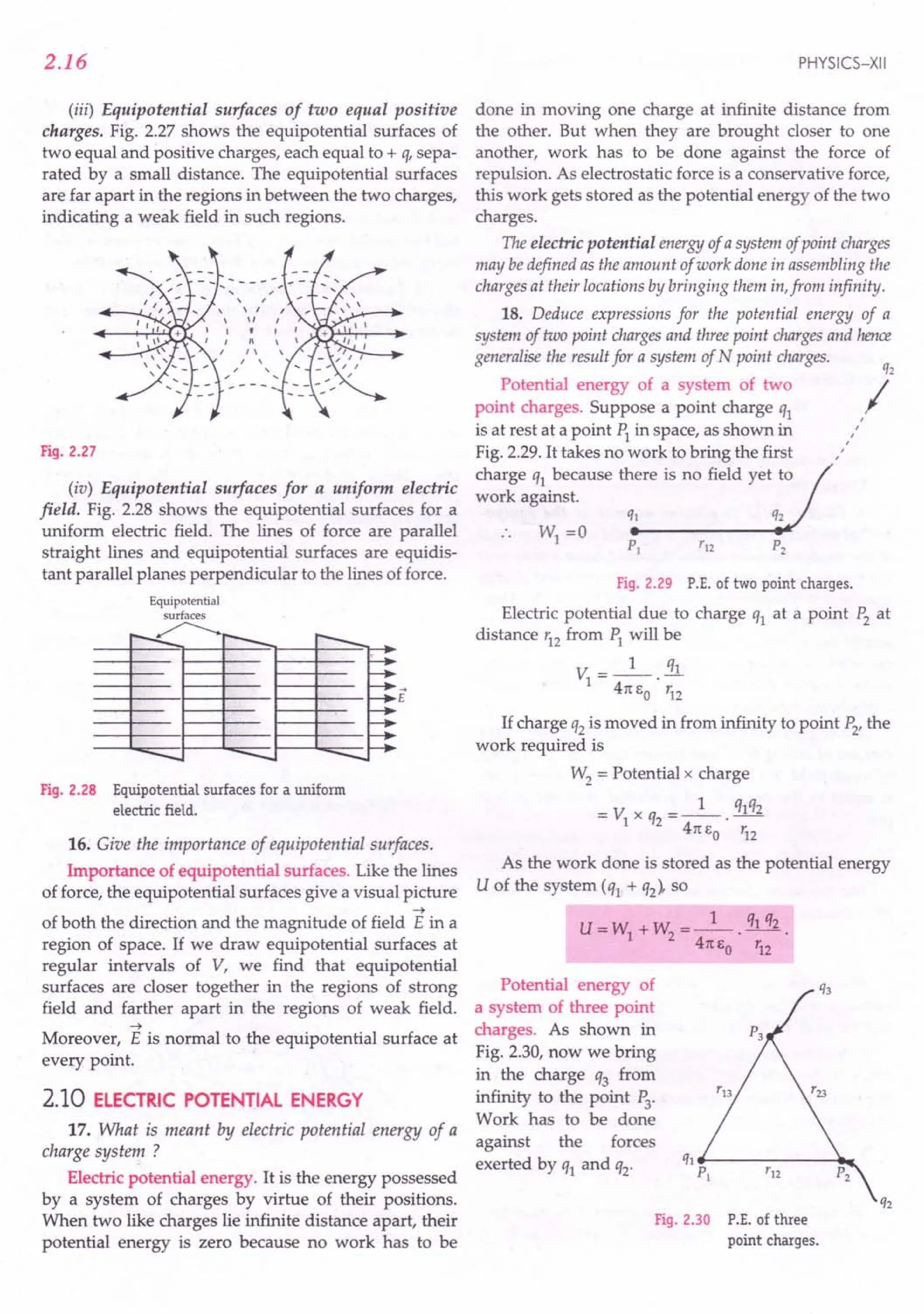
![ELECTROSTATIC POTENTIAL AND CAPACITANCE
Therefore
W3 = Potential at point P3 due to q1 and q2
x charge q3
or W3 = _1_ [!!.L+ 31..] x q3 = _1_ [q1q3 + q2q3]
41t EO r13 123 41t EO r13 r23
Hence the electrostatic potential energy of the
system q1 + q2 + q3 is
U = Total work done to assemble the three charges
=W1 + W2 + W3
or U= _1_ [q1q2 + q1q3 + q2q3]
41t EO r12 r13 r23
Potential energy of a system of N point charges.
The expression for the potential energy of N point
charges can be written as
U=_l_ L qiqj =.!.._1_ f f fJiqj
41t EO all pairs 'ij 2 41t EO i = 1 j = 1 'i;
i7' j
As double summation counts every pair twice, to
avoid this the factor 1/2 has been introduced.
NOT E The potential at jth charge due to all other
charges can be written as
V. = I3£
} k= 1 r'k
k7'j }
The expression for P.E. of N point charges can be written as
U=1. ~ q,[ _1_ I qk ]=1. Iq.Y.
2j=1 } 41t EO k= 1 rl
2j=1 } }
k7' } }
For Your Knowledge
~ Electric potential energy is a scalar quantity. While
finding its value, the value of various charges must be
substituted with their proper signs.
~ The potential energy of two like charges (ql q2 > 0) is positive.
As the electrostatic force is repulsive, so a positive
amount of work has to be done against this force to
bring the charges from infinity to a finite separation.
~ The potential energy of two unlike charges (ql q2 < 0) is
negative. As the electrostatic force is attractive, so a
positive amount of work has to be done against this
force to take the charges from the given locations to
infinity. Conversely, a negative amount of work is
needed to bring the charges from infinity to the present
locations, so the potential energy is negative.
~ As electrostatic force is a conservative force, so the
potential energy of a charge configuration is inde-
pendent of the manner in which the charges are
assembled to the present locations. The potential energy
is a characteristic of the present state of configuration,
not on how this state is attained.
2.17
~ Positive potential energy implies that work can be
obtained by releasingthe charges,while negative potential
energy indicates that an external agency will have to do
work to separate the charges infinite distance apart.
~ Electric potential is a characteristic of an electric field, it
does not matter whether a charged object is placed in
that field or not. It is measured in JC-1
or volt. On the
other hand, electric potential energy is the energy of a
charged object in an external electric field. More
precisely, it is the energy of the system consisting of the
charged object and the external electric field (or charges
producing that field). It is measured in joule.
2.11 POTENTIAL ENERGY IN AN
EXTERNAL FIELD
19. Write an expression for the potential energy of a
single charge in an external field. Hence define electric
potential.
Potential energy of a single charge. We wish to
determine the potential energy of a charge q in an
~
external electric field E at a point P where the corres-
ponding external potential is V. By definition, V at a
point P is the amount of work done in bringing a unit
positive charge from infinity to the point P. Thus, the
work done in bringing a charge q from infinity to the
point P will be qV, i.e., W = qV
This work done is stored as the potential energy of
~
the charge q. If r is the position vector of point P
relative to some origin, then
~ . ~
U(r)=qV(r)
P. E. of a charge in an external field
= Charge x external electric potential
As V= U
q
So we can define electric potential at agiven point in
an external field as the potential energy of a unit positive
charge at that point.
20. Write an expression for the potential energy of
two point charges ql and Q2' separated by distance rin an
electric field E.
Potential energy of a system of two point charges in
~ ~
an external field. Let V(r1
) and V(r2
) be the electric
~
potentials of the field E at the points having position
~ ~
vectors r1
and r2
as shown in Fig. 2.31.
~
Work done in bringing q1 from 00 to r1 against the
external field](https://image.slidesharecdn.com/slaroraclass12thphysicsbyrockytrickster-250318042948-c8b51a5a/75/SL-ARORA-CLASS-12TH-PHYSICS-BY-ROCKY-TRICKSTER-pdf-108-2048.jpg)
![2.18
0
--
'I
I Source
, charges
-='=- - ofE Q2VCr;)
Fig. 2.31 P.E. of two charges in an external field.
~
Work done in bringing q2 from OC! to '2 against the
external field
~
= q2V( '2)
Work done on q2 against the force exerted by q1
_1_ q1q2
4m:o' '12
where '12 is the distance between q1 and q2'
Total potential energy of the system = The work
done in assembling the two charges
~ ~ 1 q1q2
U=q1V( 1J)+q2V('2)+--'-
41t1:o '12
or
21. Define electron volt. Express it in joule.
Units of electrostatic potential energy. Suppose an
electron (q = 1.6 x 10⁻¹⁹ C) is moved through a potential
difference of 1volt, then the change in its P.E. would be
I:J.U = q I:J.V =1.6 x 10-19 ex 1v =1.6 x 10⁻¹⁹ J
This is a commonly used unit of energy in atomic
physics and we call it electron volt (eV).
Thus electron volt is the potential energy gained or lost by
an electron in moving through a potential difference of 1volt.
1eV = 1.6 x 10⁻¹⁹ J
Multiples and submultiples of eV
1meV (milli electron volt)
= 10- 3 eV = 1.6 x 10⁻²² J
1keY (kilo electron volt)
= 103 eV = 1.6 x 10⁻¹⁶ J
1MeV (million electron volt)
= 106 eV = 1.6 x 10⁻¹³ J
1GeV (giga electron volt)
= 109
eV =1.6 x 10-to J
1TeV (tera electron volt)
= 1012 eV = 1.6 x 10⁻⁷ J.
PHYSICS-XII
2.12 POTENTIAL ENERGY OF A DIPOLE IN
A UNIFORM ELECTRIC FIELD
22. Derive an expression for the potential energy of a
dipole in a uniform electric field. Discuss the conditions of
stable and unstable equilibrium.
Potential energy of a dipole placed in a uniform
electric field. As shown in Fig. 2.32, consider an electric
~
dipole placed in a uniform electric field E with its
~
dipole moment p making an angle 8 with the field.
Two equal and opposite forces + q E and - q E act on
its two ends. The two forces form a couple. The torque
exerted by the couple will be
't = qE x 2a sin 8 = pE sin 8
where q x 2a = p, is the dipole moment.
+q ->
.0....:.... ...•. +qE
->
-----------r~~~--~----~E
: 2a sin e
->
-qE .•.••.--a:
-q
Fig. 2.32 Torque on a dipole in a uniform electric field.
1£ the dipole is rotated through a small angle d8
against the torque acting on it, then the small work
done is
dW = 't d8 = pE sin 8 d8
The total work done in rotating the dipole from its
orientation making an angle 81
, with the direction of
the field to 82
will be
82
W = f dW = f pE sin 8 d8
~
= pE [- cos 8]~ = pE (cos 81 - cos 82)
This work done is stored as the potential energy U
of the dipole.
.. U = pE (cos 81 - cos 82)
1£ initially the dipole is oriented perpendicular to
the direction of the field (81
= 90°) and then brought to
some orientation making an angle 8 with the field
(82
= 8), then potential energy of the dipole will be
U = pE (cos 90° - cos 8) = pE (0 - cos 8)
~ ~
or U = - pE cos 8 = - P . E](https://image.slidesharecdn.com/slaroraclass12thphysicsbyrockytrickster-250318042948-c8b51a5a/75/SL-ARORA-CLASS-12TH-PHYSICS-BY-ROCKY-TRICKSTER-pdf-109-2048.jpg)
![ELECTROSTATIC POTENTIAL AND CAPACITANCE
Special Cases
1. Position of stable equilibrium. When e =0°,
u= - pE cos 0° = - pE
Thus the potential energy of a dipole is minimum
when its dipole moment is parallel to the external
field. This is the position of stable equilibrium.
2. Position of zero energy. When e = 90°,
U = - pE cos 90° =0.
Thus the potential energy of a dipole is zero
when it is held perpendicular to the external
field. This can be explained as follows. If we
hold the dipole perpendicular to the electric
field and bring it from infinity into the field,
then the work done on charge + q by the
external agent is equal to the work done on
charge - q.The net work done on the dipole will
be zero and hence its potential energy is zero.
3. Position of unstable equilibrium. When e = 180°,
U = - pE cos 180° = + pE
Thus the potential energy of a dipole is maximum
when its dipole moment is antiparallel to the external
field. This is the position of unstable equilibrium.
Examples based on
Electric Potential Energy
Formulae Used
1. Electric potential energy of a system of two point
charges,
U=_I_. q1q2
41t eo 'i2
2. Electric potential energy of a system of N point
charges,
U=_l_ L qjqk
41t eo all pairs rjk
3. Potential energy of an electric dipole in a uniform
electric field,
u= - pE(cos 82
-cos~)
If initially the dipole is perpendicular to the field
E, ~ = 90° and 82
= 8 (say), then
-4 -4
U = - pE cos 8 = - P . E
If initially the dipole is parallel to the field E,
~ = 0° and 82
= 8 (say), then
U = - pE(cos 8-1) = pE(I-cos 8)
Units Used
Charges are in coulomb, distances in metre,
energy in joule or in electron volt (eV) and dipole
moment in coulomb metre (Cm).
leV = 1.6 x 10⁻¹⁹ C, 1MeV = 1.6 x 10⁻¹³ C.
2.19
Example 22
(a) Determine the electrostatic potential energy of a
system consisting of two charges 7 ~C and - 2 ~C
(and with no external field) placed at (-9 em,O,O)
and (9 em,a,0) respectively.
(b) How much work is required to separate the two
charges infinitely away from each other ?
(c) Suppose the same system of charges is now placed in
an external electric field E = A (1/ 1) ;
A =9 x 10⁵ Cm-2. What would the electrostatic
energy of the configuration be ? [NCERT]
Solution. (a) q1 = 7 ~C = 7 x 10⁻⁶
c,. q2 = - 2 x 10⁻⁶
C,
r=18 em =0.18 m
Electrostatic potential energy of the two charges is
U=_I_. q1q2
41t eo r
9 x 109
x 7 x 10-6
x (- 2) x 10-6
--------'-----'--- = -0.7 J.
0.18
(b) Work required to separate two charges infinitely
away from each other,
W = U2 - U1 =0 - U =-(-0.7)=0.7 J.
(c) Energy of the two charges in the external electric field
= Energy of interaction of two charges with the
external electric field
+ Mutual interaction energy of the two charges
= q1V (r1)+ q2V (r2)+ _1_ ql~2
4m;0 r:
= q1 A + q2 A + _1_ q1q2
1. r2 4m;0 1
= [7~C + -2~C] x 9 x 10⁵
Cm-2
-0.7 J
0.09 m 0.09m
= (70 -20) -0.7 = 50 - 0.7 = 49.3 J.
Example 23. Three charges - q, + Q and - q are placed at
equal distances on a straight line. If the potential energy of
the system of three charges is zero, find the ratio Q / q.
Solution. As shown in Fig. 2.33, suppose the three
charges are placed at points A, Band C respectively on
a straight line, such that AB = BC = r.
-q +Q
• •
-q
•
A B
I--- r '1'
C
r ------I
Fig. 2.33
As the total P.E. of the system is zero, so
_1_ [- qQ + (- q)(-q) + Q(-q)] =0
41t EO r 2r r
or - Q + !t. - Q = a or 2 Q = !t. or Q =.!. = 1 : 4.
2 2 q 4](https://image.slidesharecdn.com/slaroraclass12thphysicsbyrockytrickster-250318042948-c8b51a5a/75/SL-ARORA-CLASS-12TH-PHYSICS-BY-ROCKY-TRICKSTER-pdf-110-2048.jpg)
![2.20
Example 24. Two positive point charges of 0.2 /lC and
0.01 /lC are placed 10 em apart. Calculate the work done in
reducing the distance to 5 em.
Solution. Here q1 = 0.2 x 1O-6C, q2 = 0.01 x 10⁻⁶C
Initial separation (r) = 10 em = 0.10 m
Final separation (r
f
) = 5 em = 0.05 m
Work done = Change in potential energy
= Final P. E. - Initial P. E.
__ 1_ q1q2__ 1_ q1q2- q1q2 [~-.!l
- 4m,0· r
f
4m,o '; - 41tEo r
f
';
= 0.2 x 10-6 x 0.01 x 10-6 x 9 x 109 [_1 l_J
0.05 0.10
= 1.8 x 10⁻⁴ J.
Example 25. Two electrons, each moving with a velocity of
106
ms-l, are released towards each other. What will be the
closest distance of approach between them ?
Solution. Let robe the distance of closest approach
of the two electrons. At this distance, the entire K.E. of
the electrons changes into their P.E. Therefore,
1 2 1 2 1 ee
-mv +-mv =---
2 2 41tEo ~
1 e2 9 x 109 x (1.6 x 10-19)2
r, = --. -- = ----'-,;-;---~;O-'---
o 41tEO mv2 9.1 x 10-31 x (106)2
= 2.53 x 10-tO
m.
Example 26. Two particles have equal masses of5.0 g each
and opposite charges of +4 x 10⁻⁵ C and -4.0 x 10⁻⁵ C. They
are released from rest with a separation of 1.0 m between
them. Find the speeds of the particles when the separation is
reduced to 50 em.
Solution. Here m = 5.0 g = 5 x 10⁻³ kg.
q =±4x 1O-5
C, r
1
=1.0 m, r2
=50 em =0.50 m
Let v = speed of each particle at the separation of
50 cm.
From energy conservation principle,
K.E. of the two particles at 50 em separation
+ P.E. of the two particles at 50 em separation
= P.E. of the two particles at 1.0 m separation
.!mv2 + .!mv2 + _1_. q1q2 = _1_. q1q2
2 2 47tEO r2 41tEO r1
mv2 = q1q2 [~_ ~Jl or v2 = q1q2 [r2 - r1]
41tEO r1 r2 41tEOm r1
r2
v2 = 4 x 10⁻⁵
x (-4 x 10-
5
) x 9 x 10
9
[0.50 -1.0]
5 x 10⁻³ 1.0 x 0.50
= 2880 or v = 53.67 ms-t.
PHYSICS-XII
Example 27. Four charges /~q -.qD
are arranged at the corners of a
square ABCD of side d as
shown in Fig. 2.34. (i) Find the
work required to put together
this arrangement. (ii) A charge
qois brought to the centre E of B __._----- .• C
the square, the four charges - q + q
being held fixed at its corners. Fig. 2.34
How much extra work is
needed to do this ? [NCERT ; CBSE F 15]
Solution. (i) Given AB = BC = CD = AD = d
.. AC= BD=~d2 + d2 =..fi d
d ,
,
Work required to put the four charges together
= Total electrostatic P.E. of the four charges
=_I_[qAqB + qAqC+ qAqO+ qBqC+ qBqO+ qcqo]
47t EO AB AC AD BC BD CD
_ 1 [q2 q2 q2 q2 q2 q2]
- 41tEO - d + J2d- d -d + J2 d - d
=-L(4-J2).
47t Eo
(ii) Extra work needed to bring charge qo to centre E
W = qox Electrostatic potential at E due to the
four charges
-q[ q + -q
- 0 41tEo(d I ..fi) 41tEo(d I ..fi)
+ q + -q ]-0
41tE
o
(dl..fi) 41tE
o
(dl..fi) -.
Example 28. Three point
charges, +Q,+2Q and -3Q A(+Q)
are placed at the vertices of an
equilateraltriangle ABt ofside I
(Fig. 2.35). If these charges are
displaced to the midpoints ~,
1 and C1
respectively, find the
amount of the work done in B(+ 2Q) B1 q- 3Q)
shifting the charges to the new
locations. [CBSE OD 2015] Fig. 2.34
Solution. ~ 1 = 1 C1 =~ C1
= AB =.i
2 2
Initial P.E. of the system is
u. = _1_[QX2Q + 2Qx (-3Q) + QX(-3Q)]
I 41tEo I I I
__ 1_7Q2
41tEO' I](https://image.slidesharecdn.com/slaroraclass12thphysicsbyrockytrickster-250318042948-c8b51a5a/75/SL-ARORA-CLASS-12TH-PHYSICS-BY-ROCKY-TRICKSTER-pdf-111-2048.jpg)
![ELECTROSTATIC POTENTIAL AND CAPACITANCE
Final P.E. of the system is
U ==_1_[QX2Q + 2Qx(-3Q) + QX(-3Q)]
f 41tEo 1/2 1/2 1/2
1 14Q2
- 41tEo ·-1-
Work done ==Uf - U,
1 14Q2 1 7Q2 1 7Q2
==---.-- + ---- ==---.-- .
41tEo I 41tEo I 41tEo I
Example 29. An electric dipole of length 2 em is placed
with its axis making an angle of 60° to a uniform electric
field of 10
5
uc:'. If it experiences a torque of 8J3 Nm,
calculate the
(i) magnitude of the charge on the dipole, and
(ii) potential energlJ of the dipole. [CBSE OD 2000]
Solution. Here 2a ==2 em ==0.02 m, 8 ==60°,
E ==10
5
NC 1: ==8J3 Nm
(i) T == pE sin 8 ==q x 2a x E sin 8
8J3 ==q x 0.02 x 10⁵ x sin 60°
== 8J3 x 2 ==8 x 10⁻³ C.
q 0.02 x 10⁵ x J3
(ii) P.E. of the dipole is
U ==- pE cos e ==- q x 2a x E cos 8
==- 8 x 10-3 x 0.02 x 105 x cos 60° ==- 8 J.
Example 30. An electric dipole of length 4 em, when placed
with its axis making an angle of 60° with a uniform electric
field experiences a torqueoj 4 J3 Nm. Calculate the (i) magni-
tude of the electric field, (ii) potential energy of the dipole, if
the dipole has charges of ± 8 nC. [CBSE OD 04 ; D 06C, 14]
Solution. Here 2 a ==4 cm ==0.04 m, 8 ==60°,
T ==4 J3 Nm, q ==8 nC ==8 x 10- 9 C
Dipole moment,
p ==q x 2a ==8 x 10-9 x 0.04 ==0.32 x 10⁻⁹ Cm.
(i) As 1: ==pE sin 8
E==
__ 1:_
P sin 8 0.32 x 10⁻⁹
x sin 60°
==4 J3 x 10
9
x 2 ==2.5 x 10¹⁰ NCl.
0.32 x J3
(ii) U ==- pE cos e
==-0.32 x 10-9
x 2.5 x 1010 x cos 60° ==- 4 J.
Example 31. A molecule of a substance has permanent
electric dipole moment equal to 10-
29
Cm. A mole of this
substance is polarized (at low temperature) t:y applying a
strong electrostatic field of magnitude (10 Vm-l
). The
direction of thefield is suddenly changed by an angle of 60°.
or
2.21
Estimate the heat released by the substance in aligning its
dipoles along the new direction of the field. For simplicity
assume 100% polarization of the sample. [NCERT]
Solution. Here p ==10-29
Cm, E ==106
Vm-1,
8 ==60°, N ==6 x 10
23
Work required to bring one dipole from position
8 ==0° to position e is
W == pE - pE cos 8 ==pE(1-cos 8)
==10-29
x 106
(1- cos 60°) J ==0.5 x 10⁻²³
J
Work required for one mole of dipoles
==W x N ==0.5 x 10-
23
x 6 x 10
23
==3.0 J
Heat released = Loss in P.E.= Work done = 3.0 J.
jOrOblems For Practice
1. Two point charges + 10 ~C and - 10 ~C are
separated by a distance of 2.0 em in air. (i) Calculate
the potential energy of the system, assuming the
zero of the potential energy to be at infinity.
(ii) Draw an equipotential surface of the system.
[CBSE D 04] (Ans. - 45 J)
2. Two point charges A and B of values + 15 IlC and
+ 9 IlC are kept 18 em apart in air. Calculate the
work done when charge B is moved by 3 cm
towards A. [CBSE OD 2000] (Ans. 1.35 J)
3. Two point charges 20 x 1O-6C and -4 x 1O-6C are
separated by a distance of 50 cm in air. (i) Find the
point on the line joining the charges, where the
electric potential is zero. (ii) Also find the electro-
static potential energy of the system. [CBSE OD OS]
[Ans. (i) 41 em from the charge of 20 x 10-6 C
(ii) - 144 Jl
4. Two charges, of magnitude 5 nC and - 2 nC, are
placed at points (2 em, 0, 0) and (x em, 0, 0) in a
region of space, where there is no other external
field. If the electrostatic potential energy of the
system is - O.5IlJ, what is the value of x ?
[CBSE D OSC] (Ans. x = 4 em)
5. Three point charges are arranged as shown in
Fig. 2.36. What is their mutual potential energy ?
Take q ==1.0 x 10--4 C and a ==10 em. (Ans. 0.27 J)
D
q a q
Fig. 2.36 Fig. 2.37
6. Determine potential energy of the charge configu-
ration shown in Fig. 2.37. ( q2 r; J
Ans.--(-.,,2)
41t Eo a](https://image.slidesharecdn.com/slaroraclass12thphysicsbyrockytrickster-250318042948-c8b51a5a/75/SL-ARORA-CLASS-12TH-PHYSICS-BY-ROCKY-TRICKSTER-pdf-112-2048.jpg)
![2.22
7. Find the amount of work
done in arranging the
three point charges, on
the vertices of an equi-
lateral triangle ABC, of
side 10 em, as shown in
the adjacent figure.
[CBSE Sample Paper 2011]
8e------,e C
6~C - 6~C
(Ans. - 3.24 J )
8. Calculate the work done to dissociate the system of
three charges placed on the vertices of a triangle as
shown in Fig. 2.38. Here q = 1.6 x 10⁻¹⁰
C.
[CBSE D 08; OD 13] (Ans. 2.304 x 10⁻⁸ J)
q
ql~:4
q,~q,
Fig. 2.39
- 4q ~----- __ + 2q
lOan
Fig. 2.38
9. What is the electrostatic potential energy of the
charge configuration shown in Fig. 2.39 ? Take
ql = + 1.0 x 10⁻⁸ C, q2 = - 2.0 x 10⁻⁸ C,
q3 = + 3.0 x 10⁻⁸ C, q4 = + 2.0 x 10⁻⁸ C
and a = 1.0 metre. (Ans. - 6.36 x 10⁻⁷
J)
10. Three point charges + q, + 2q and Qare placed at the
three vertices of an equilateral triangle. Find the value
of charge Q (in terms of q), so that electric potential
energy of the system is zero. (Ans. Q = - 2q / 3)
11. An electron (charge = -e) is placed at each of the
eight comers of a cube of side a and an a-particle
(charge = + 2e) at the centre of the cube. Calculate
the potential energy of the system.
(Ans. 3.89 x 10lOe2
/ a joule)
12. Two identical particles, each having a charge of
2.0 x 10⁻⁴ C and mass of 10g, are kept at a
separation of 10em and then released. What would
be the speeds of the particles when the separation
becomes large? (Ans. 600 ms ")
13. Find the amount of work done in rotating an electric
dipole, of dipole moment 3.2 x 10⁻⁸ em, from its
position of stable equilibrium, to the position of
unstable equilibrium, in a uniform electric field of
-intensity 104N / C. [CBSE Sample Paper 2011]
(Ans. 6.4 x 10⁻⁴ J)
14. An electric dipole consists of two opposite charges
each of magnitude 11lC separated by 2 em. The
dipole is placed in an external electric field of
1cPNC-1
. Find (i) the maximum torque exerted by
PHYSICS-XII
the field on the dipole (ii) the work which the
. external agent will have to do in turning the dipole
through 180° starting from the position e= 0°.
[Ans. (i) 2 x 10⁻³ Nm (ii) 4 x10⁻³ JJ
HINTS
1. U=_l_. qlq2
41tEO r
9 10 x 10-6 x(-10) x 10-6
=9xlO x 2 =-45J.
2.0 x 10-
For equipotential surface, see Fig. 2.26 on page 2.15.
2. W = Final P.E. - Initial P.E.
= 4~q:J~-{]
= 9 x 109 x 15 x 10-6 x 9 x 10-6 [100 _ 100]
15 18
= 1.35 J.
3. (i) Suppose the point of zero potential is located at
distance x metre from the charge of 20 x 10-6 C.
Then, V = _1_ [20 x 10-6 _ 4 x 10⁻⁶] = 0
41tEo x 0.50 - x
This gives x = 0.41m = 41 em.
(ii) U = _1_. qlq2
41tEo r
9 x 109
x 20 x 10-6 x(-4) x10-6
-------'--'--- = -1.44 J.
0.50
4. U= _1_ qlq2
41tEo r
-6 9 x 109 x 5 x 10-9 x(-2) x 10-9
:. - 0.5 x 10 = 2
(x-2)xl0
•
On solving, x = 4 em
3 q2
5. U=---
41tEo a
3 x9 x 109
x(1.0 x10-4)3 = 0.27 J.
0.10
7. W =_l_[qAqB + qAqC + qBqC]
41tEo AB AC BC
=_1_[!Li+ q(-q) + q(-q)]
41tEo r r r
1 l 9 x109 x(6x10-6)2
= - -- = - J = - 3.24 J.
41tEor 0.10 ..
8. Initial P.E. of the three charges,
U. = _1_ [ Ihq2 + q2q3 + qlq3]
I 41tf.:o r r r](https://image.slidesharecdn.com/slaroraclass12thphysicsbyrockytrickster-250318042948-c8b51a5a/75/SL-ARORA-CLASS-12TH-PHYSICS-BY-ROCKY-TRICKSTER-pdf-113-2048.jpg)
![ELECTROSTATIC POTENTIAL AND CAPACITANCE
=_1_[q(-4q) + (-4q)x2q + qX2q]
41tEo r r r
1 10q2 9x109x10x(1.6xlO-10)2
41tEo -r- = - 0.10 J
= - 2.304 x 10⁻⁸ J
Final P.E., Uf = 0
Work required to dissociate the system of three
charges,
W = U
f
- u, = 2.304 x 10⁻⁸
J.
9. U = _1_ [q1q2 + q~3 + %q4 + q2q3+ q~4 + q3q4]
41tEo a v2a a a v2a a
=; 9 x 10
9
[(1)(-2) + (1)f]) + (1)(2) + (-2)(3)
1.0 -n
+ (-2) x (2) + (3)(2)] x 10-16 J
12
9 x 109 x 10-16
12 J = -6.36 x 10-
7
J.
10. Suppose the charges + q, + 2q and Q are placed at
the comers A, Band Cof an equilateral MBC of side
a. Then
_1_ [q x 2q + q x Q+ 2q x Q] = 0
41tEo r r r
or 2q + Q + 2Q = 0 or Q = - 'lq / 3.
11. U = 9 x 10⁹ [12 (- :)( - e) + 12 (- jt e)
+ 4 (-e)(-e) +8 (-e)(2e)]
.s; ../3a/2
9 x 10
9
x 4 x e
2
[3 + 2. + ~ _ ~ lJ
a 12J3J3
36 x 109 e2 e2
---- [3 + 2.12 - 4.04] = 3.89 x 10¹⁰ - joule.
a a
12. Here q = 2.0 x 10⁻⁴ C, m = 10g = 10-2 kg I
r = lOcm = 0.10 m
Let v be the speed of each particle at infinite
separation. By conservation of energy,
P.E. of two particles at the separation of 10 em
= K.E. of the two particles at infinite separation
_1_ . ql q2 = .!. mv2 + .!. mv2
41t£o r 2 2
2 1 ql q)
or v =--.---
41tEo rm
9 x 109
x 2.0 x 10-4 x 2.0 x 10-4 4.
0.10 x 10-2 = 36 x 10
v= 600 ms-1
•
2.23
13. Here ' = 0°, 82 = 180°, P = 3.2 x 10⁻⁸ Cm,
E = 104
N/C
W = pE(cos, -cos82
)
=3.2xlO-8
x104(cos OO-cos180°)
= 3.2 x 10⁻⁴ x(l + 1)= 6.4 x10⁻⁴ J.
14. P = q x 2a = 10-6 xO.02 = 2 x 1O-8
Cm
(i) "max = pEsin 90° = 2 x 10-8
x 1ef xl
= 2 x 10⁻³
Nm.
(ii) W = pE(cos ' -cos 82)
= 2 x 10-8
x 105(cos OO-cos180°)
= 2 x 10⁻³
(1+ 1)= 4 xlO-3
J.
2.13 CONDUCTORS AND INSULATORS
23.What are conductors and insulators? Why were
insulators called dielectrics and conductors non-electrics ?
Conductors and insulators. On the basis of their
behaviour in an external electric field, most of the
materials can be broadly classified into two categories:
1. Conductors. These are the substances which allow
large scale physical movement of electric charges through
them when an external electricfield is applied. For example,
silver, copper, aluminium, graphite, human body, acids,
alkalies, etc.
2. Insulators. These are the substances which do not
allow physical movement of electricchargesthrough them when
an external electricfield is applied. For example, diamond,
glass, wood, mica, wax, distilled water, ebonite, etc.
The rubbed insulators were able to retain charges
placed on them, so they were called dielectrics. The
rubbed conductors (metals) could not retain charges
placed on them but immediately drained away the
charges, so they were called non-electrics.
2.14 FREEAND BOUND CHARGES
24. Discuss the various free and bound charges
present in conductors and insulators.
Free and bound charges. The difference between
the electrical behaviour of conductors and insulators
can be understood on the basis of free and bound
charges.
In metallic conductors, the electrons of the outer
shells of the atoms are looselybound to the nucleus.
They get detached from the atoms and move almost freely
inside the metal. In an external electric field, these free
electrons drift in the opposite direction of the electric
field. The positive ions which consist of nuclei and
electrons of inner shells remain held in their fixed posi-
tions. These immobile charges constitute the boundcharges.](https://image.slidesharecdn.com/slaroraclass12thphysicsbyrockytrickster-250318042948-c8b51a5a/75/SL-ARORA-CLASS-12TH-PHYSICS-BY-ROCKY-TRICKSTER-pdf-114-2048.jpg)
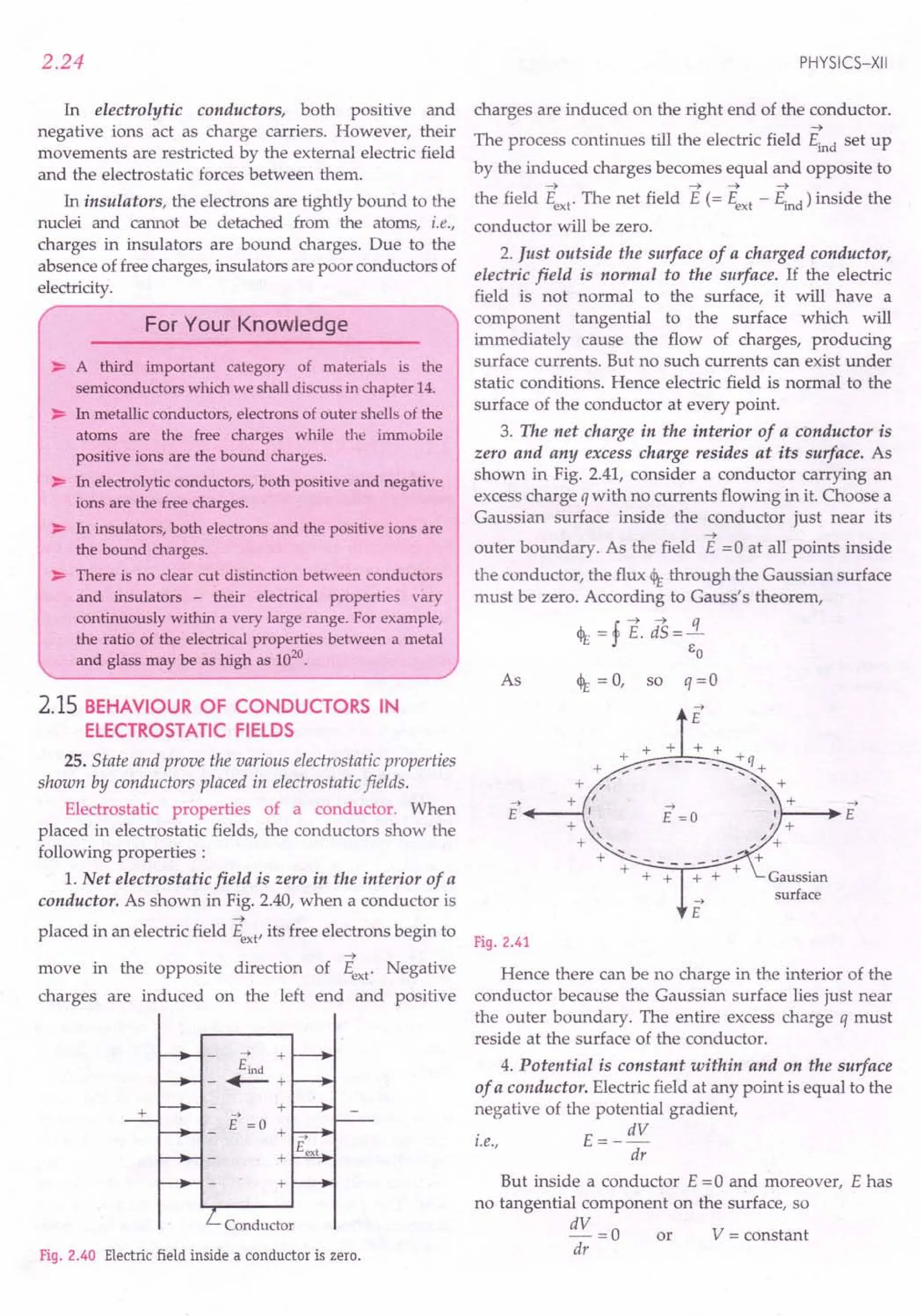
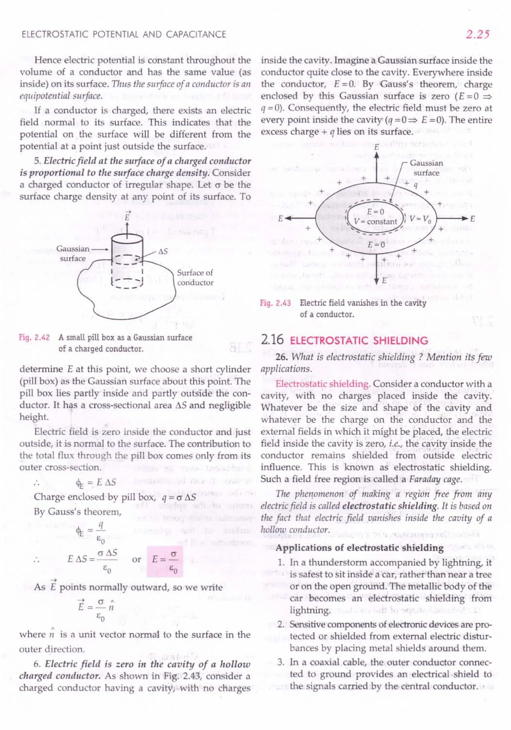
![2.26
For Your Knowledge
~ In the interior of a conductor, the electric field and the
volume charge density both vanish. Therefore,
charges in a conductor can only be at the surface.
~ Electric field at the surface of a charged conductor
must be normal to the surface at every point.
~ For a conductor without any surface charge, electric
field is zero even at the surface.
~ The entire body of each conductor, including its
surface, is at a constant potential.
~ If we have conductors of arbitrary size, shape and
charge configuration, then each conductor will have a
characteristic value of constant potential which may
differ from one conductor to another.
~ A cavity inside a conductor is shielded from outside
electrical disturbances. However, the electrostatic
shielding does not work the other way round. That is,
if we place charges inside the cavity, the exterior of
the conductor cannot be shielded from the electric
fields of the inside charges.
2.17 ELECTRICAL CAPACITANCE OF A
CONDUCTOR
27. Define electrical capacitance of a conductor. On
which factors does it depend?
Electrical capacitance of a conductor. The electrical
capacitance of a conductor is the measure of its ability to hold
electric charge. When an insulated conductor is given
some charge, it acquires a certain potential. If we
increase the charge on a conductor, its potential also
increases. If a charge Q put on an insulated conductor
increases its potential by V, then
Qoc V or Q= CV
The proportionality constant C is called the
capacitance of the conductor. Thus
. Charge
Capacitance = --"""-
Potential
Hence the capacitance of a conductor may be defined
as the charge required to increase the potential of the conductor
by unit amount.
The capacitance of a conductor is the measure of its
capacity to hold a large amount of charge without running
a high potential. It depends upon the following factors :
1. Size and shape of the conductor.
2. Nature (permittivity) of the surrounding medium.
3. Presence of the other conductors in its neigh-
bourhood.
or
It is worth-noting that the capacitance of a con-
ductor does not depend on the nature of its material
and the amount of charge existing on the conductor.
PHYSICS-XII
28. Define the unit of capacitance for a conductor.
Give its dimensions.
Units of capacitance. The 51 unit of capacitance is
farad (F), named in the honour of Michael Faraday.
The capacitance of conductor is 1farad if the addition
of a charge ofl coulomb to it, increases its potential by 1volt.
:. 1 farad = 1 coulomb or 1F = 1C = 1cv '
1 volt 1 Y
One farad is a very large unit of capacitance. For
practical purposes, we use its following submultiples:
1 millifarad = 1mF = 10-3
F
1 microfarad = IIlF = 10-6F
1 picofarad = 1pF = 10-12F
Dimensions of capacitance.The unit of capacitance is
1 F
_ 1C _ 1 C _1 C2 _ 1(As)2
------------
1Y 1J/ C 1J 1Nm
.. Dimensions of capacitance
2 2
A T =[~lL-2y4A2]
MLr2
.L
2.18 CAPACITANCE OF AN ISOLATED
SPHERICAL CAPACITOR
29. Obtain an expression for the capacitance of an
isolated spherical conductor of radius R.
Capacitance of an iso-
lated spherical conductor.
Consider an isolated sphe-
rical conductor of radius R.
The charge Q is uniformly
distributed over its entire
surface. It can be assumed
to be concentrated at the
centre of the sphere. The
potential at any point on the
Fig. 2.44 Capacitance of a
surface of the spherical
spherical conductor.
conductor will be
V=_I_. Q
41t EO R
Capacitance of the spherical conductor situated
in vacuum is
Clearly, the capacitance of a spherical conductor is
proportional to its radius.](https://image.slidesharecdn.com/slaroraclass12thphysicsbyrockytrickster-250318042948-c8b51a5a/75/SL-ARORA-CLASS-12TH-PHYSICS-BY-ROCKY-TRICKSTER-pdf-117-2048.jpg)
![ELECTROSTATIC POTENTIAL AND CAPACITANCE
Let us calculate the radius of the spherical
conductor of capacitance 1 F.
R = _1_. C =9 x 10⁹ mF-1.1 F
4rc So
= 9x 10⁹m =9 x 10⁶
km
This radius is about 1500 times the radius of the
earth (-6 x 10³
km).So we conclude:
1. One farad is a very large unit of capacitance.
2. It is not possible to have a single isolated
conductor of very large capacitance.
For Your Knowledge
~ The formula: C = 41t EO R is valid for both hollow and
solid spherical conductors.
C
As E =--
o 41t R
So the 51 unit of EO can be written as farad per metre
(Fm-1
). From Coulomb's law, the 51 unit of EO comes
out to be C2
N-1
m-2
. Both of these units are equivalent.
~ The farad (1F = 1Cy-l) is an enormously large unit
of capacitance because the coulomb is a very big unit
of charge while the volt is the unit of potential having
reasonable size.
Formulae Used
1. Capacitance of a spherical conductor of radius R,
C =4rcso R
. Charge
2. Capacitance = -----'~
Potential
or
Units Used
Charge is in coulomb, potential in volt and
capacitance in farad (F).
Example 32.An isolated sphere has a capacitance 50 pF.
(i) Calculate its radius. (ii) How much charge should be
placed 011 it to raise its potential to 104
V ?
Solution. Here C = 50 pF = 50 x 10-12
F, V = 104
V
(i) R =_1_. C =9x 10⁹mF-1 x SOx 10-12 F
4rcSo
= 45 x 1O-2
m = 45 em.
(ii) q = CV = 50 x 10-12 x 104 = 5 x 10⁻⁷
C = 0.5 1lC.
Example 33. Twenty seven spherical drops of radius 3 mm
and carrying 10-12
C of charge are combined toform a single
drop. Find the capacitance and the potential of the bigger
drop. [Haryana 01]
2.27
Solution. Let rand R be the radii of the small and
bigger drops, respectively.
Volume of the bigger drop
= 27 x Volume of a small drop
. A rcR3 = 27 x A rcr3
t.e., 3 3
or R =3r=3 x 3 mm=9 x 10⁻³
m
.'. Capacitance of the bigger drop is
C = 4rcso R = _1-
9
.9 x 10-3 F
9 x 10
= 10-12
F = 1 pF
Charge on bigger drop
q = 27 x Charge on a small drop
=27x 10-12 C
.'. Potential of bigger drop is
q 27 x 10-12
V= - = =27 V.
C 10-12
Example 34.Eight identical spherical drops, each carrying
a charge 1nC are at a potential of900 Veach. All these drops
combine together to form a single large drop. Calculate the
potential of this large drop. (Assume no wastage of any kind
and take the capacitance of a sphere of radius r as
proportional to r). [eBSE Sample Paper 15]
Solution.
Capacitance of each small drop, C ex: r => C = kr
Charge on each small drop, q = CV = (krx 900)C
Charge on large drop, q =8q = 7200kr C
Volume of a large drop =Volume of 8 small drops
ArcR3=8xArcr3 => R=81
/
3r=2r
3 3
Capacitance of large drop, C' = kR = 2kr
Hence, the potential of the large drop is
V' =!L = 7200kr = 3600 V.
C' 2 kr
Example 3S.A charged spherical conductor has a surface
charge density of 0.07 C em- 2. When the charge is increased
by 4.4 C, the surface charge density changes by
0.084 C em- 2. Find the initial charge and capacitance of the
spherical conductor.
Solution. Let q be the charge on the spherical con-
ductor and r its radius. Its surface charge density is
-q- = 0.07 C ern -2 (i)
47t? ...
When the charge is increased by 4.4 C, the surface
charge density becomes
q + 4.4 = 0.084 C cm-2 ( .. )
2 ••• II
4rc r:](https://image.slidesharecdn.com/slaroraclass12thphysicsbyrockytrickster-250318042948-c8b51a5a/75/SL-ARORA-CLASS-12TH-PHYSICS-BY-ROCKY-TRICKSTER-pdf-118-2048.jpg)
![2.28
Dividing equation (ii) by (I), we get
q + 4.4 0.084 C
--=-- or q=22
q 0.07
From equation (i), we get
~
22x7
r- - =5 cm =0.05 m
- 41t x 0.07 - 4 x 22 x 0.07
Capacitance,
C = 41t EOr = __ 1-9 x 0.05 = 5.56 x 10⁻¹² F.
9 x 10
j2)roblems ForPractice
1. Find the capacitance of a conducting sphere of
radius 10 cm situated in air. How much charge is
required to raise it to a potential of 1000 volt?
(Ans. 11 pP, 1.1 x 10⁻⁸ C)
2. Assuming the earth to be a spherical conductor of
radius 6400 km, calculate its capacitance.
[Himachal 98C; Haryana 98C]
(Ans.711IlF)
3. N drops of mercury of equal radii and possessing
equal charges combine to form a big drop. Compare
the charge, capacitance and potential of bigger drop
with the corresponding quantities ofindividual drops.
[Punjab 01]
(Ans. N, N1/3, N2/3)
HINTS
1. C = 41t EoR = _1-9 x 0.10 = 11x 10-12
F = 11 pF.
9xlO
q = CV = 11 x 10-12
p xl00G V = 1.1 x 10⁻⁸
C.
1 6
2. C=41tEoR=--9 x6.4xl0
9 x 10
= 0.711 x 1O-3p = 711 IlF.
3. Let q be the charge on each small drop and r its
radius.
Capacitance of each small drop, C = 41t EOr
Potential of each small drop, V = _1_ !1
41t Eo r
If R is the radius of the big drop, then
4 3 4 3 1/3
- nr x N = - 1tR or R = N r
3 3
Charge on the big drop, q' = Nq or
Capacitance of the big drop.
C' = 41t EO R = 41t Eo N
1
/
3
r = N
I
/
3
C
e = N1/3.
C
or
PHYSICS-XII
Potential of the big drop,
V'- 1 q' _ 1 Nq
- 41t EO • R - 41t Eo . NI/3 r
= N2/3 . __ ~ . !1= N2/3 V
47t Eo r
or
2.19 CONCEPT OF A CAPACITOR AND
ITS PRINCIPLE
30. An isolated conductor cannot have a large
capacitance, why ?
The capacitance of an isolated conductor is small.
When a conductor holds a large amount of charge, its
potential is also high. If the associated electric field
(£ = a/Eo) becomes high enough, the atoms or
molecules of the surrounding air get ionised. A
breakdown occurs in the insulation of the surrounding
medium and the charge put on the conductor gets
neutralised or leaks away. For air, the breakdown
point occurs at fields of the order of3 x 106 Vm -1. This
puts the limit on the capacitance of a conductor.
Moreover, if we tend to have a single conductor of
large capacitance, it will have practically inconvenient
large size.
31. Why does the capacitance of a conductor increase,
when an earthed connected conductor is placed near it ?
Briefly explain.
Principle of a capacitor. Consider a positively
charged metal plate A and place an uncharged plate B
close to it, as shown in Fig. 2.45. Due to induction, the
closer face of plate Bacquires negative charge and its
farther face acquires a positive charge. The negative
charge on plate Btends to reduce the potential on plate
A, while the positive charge on plate B tends to
increase the potential on A As the negative charge of
plate B is closer to plate A than its positive charge, so
the net effect is that the potential of A decreases by a
small amount and hence its capacitance increases by a
small amount.
A B A B
+ + - + + +
+ + - + + +
+ + - + + +
+ + - + + +
+ + - + + +
+ + - + + +
+ + - + + +
-i- + - + + +
+ + - + + +
+ + - + + +
+ + - + + +
+" + - + + + -
+ + - + + +
+ + - + + +
+ + - + + +
+ + - + + +
+ + - + + +
Fig. 2.45 Principle of a capacitor.](https://image.slidesharecdn.com/slaroraclass12thphysicsbyrockytrickster-250318042948-c8b51a5a/75/SL-ARORA-CLASS-12TH-PHYSICS-BY-ROCKY-TRICKSTER-pdf-119-2048.jpg)
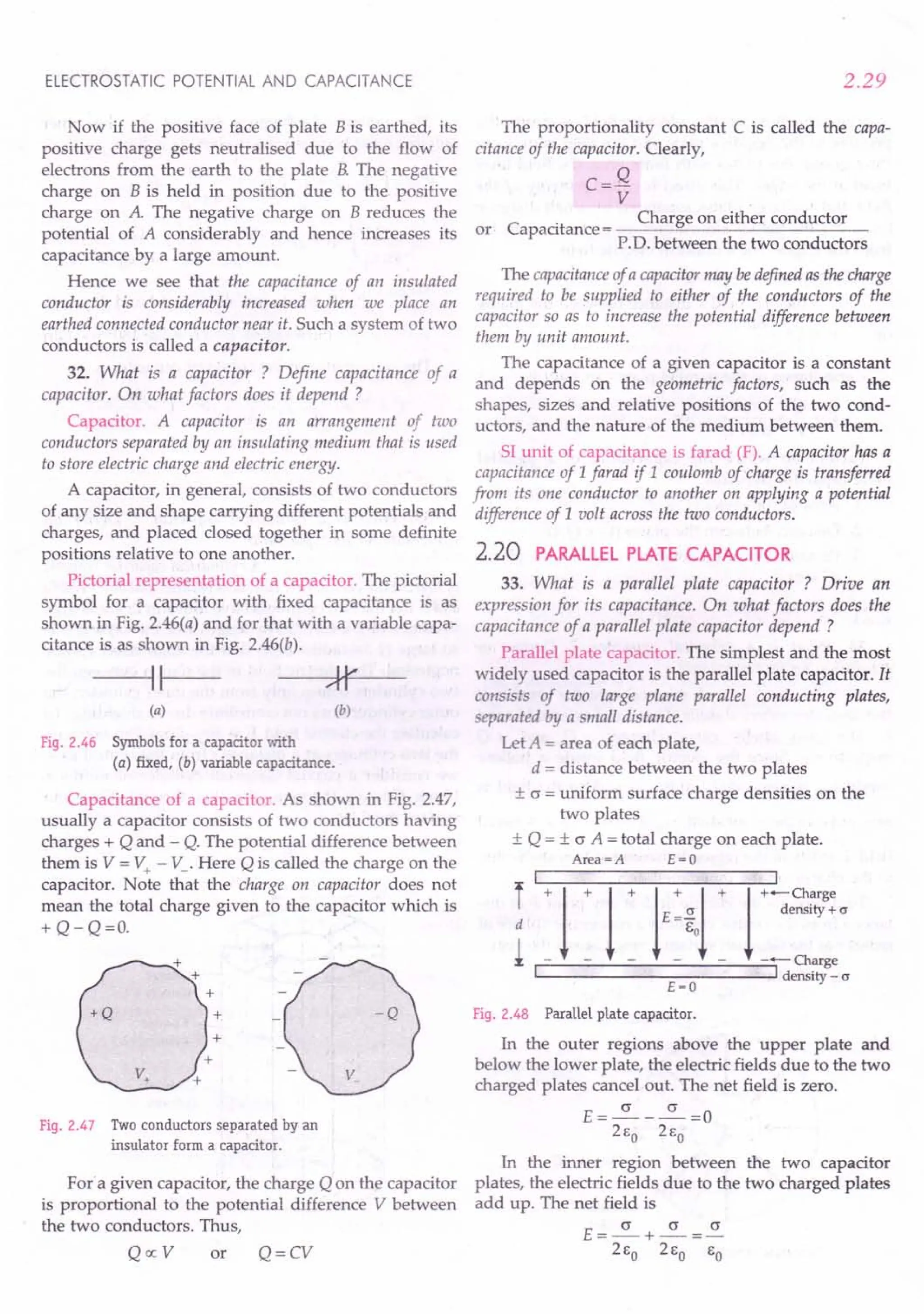
![2.30
The direction of the electric field is from the
positive to the negative plate and the field is uniform
throughout. For plates with finite area, the field lines
bend at the edges. This effect is called fringing of the
field. But for large plates separated by small distance
(A» d
2
), the field is almost uniform in the regions far
from the edges. For a uniform electric field,
P'D. between the plates
= Electric field x distance between the plates
V = Ed = ad
EO
Capacitance of the parallel plate capacitor is
C = Q = ~ or C = EoA
V ad / EO d
Factors on which the capacitance of a parallel
plate capacitor depends
1. Area of the plates (C oc A).
2. Distance between the plates (C oc 1/ d).
3. Permittivity of the medium between the plates
(COCE).
or
2.21 SPHERICAL CAPACITOR*
34. What is a spherical capacitor ? Derive an
expression for its capacitance.
Spherical capacitor. A spherical capacitor consists of
two concentric spherical shells of inner and outer radii a and
b. The two shells carry charges - Q and + Q
respectively. Since the electric field inside a hollow
-t .
conductor is zero, so E = 0 for r < a. Also the field is
-t
zero outside the outer shell, i.e., E =0 for r > b. A radial
~
field E exists in the region between the two shells due
to the charge on the inner shell only.
To determine the electric field at any point P at dis-
tance r from the centre, consider a concentric sphere of
radius r as the Gaussian surface. Using Gauss's theorem,
4t = E.4n? = Q or E=~
EO 4n Eor
£=0 Charge+Q
+
Charge-Q
Gaussian
surface
Fig. 2.49 Spherical capacitor.
PHYSICS-XII
The potential difference (caused by the inner
sphere alone) between the two shells will be
b b b
V = - f E.;t = f Edr = f ~ dr
a a a 4n EO'
Q b -2 Q [l]b Q [1 1]
=,4n EO ~ r dr = 4n EO -; a = 4n EO -;; - b
-t -t
[.: E points radially inward and dr points
-t -t
outward so E . d r = Edr 1800
= - Edr]
The capacitance of the spherical capacitor is
Q Q or C = 4n EO ab .
C=V= Q [1 1] b-a
4n EO a b
2.22 CYLINDRICAL CAPACITOR*
35. What is a cylindrical capacitor ? Derive an
expression for its capacitance.
C}lind.ica capacitor. A cylindrical capacitor consists
of two coaxial conducting cylinders of inner and outer radii a
and b. Let the two cylinders have uniform linear charge
densi ties of ± A. Cm -1. The length L of the capacitor is
so large (L» radii a or b) that the edge effect can be
neglected. The electric field in the region between the
two cylinders comes only from the inner cylinder, the
outer cylinder does not contribute due to shielding. To
calculate the electric field E at any point P in between
the two cylinders at a distance r from the central axis,
we consider a coaxial Gaussian cylinder of radius r.
Using Gauss's theorem, the flux through Gaussian
surface must be
b a
Charge
density + A.
+1-
1
+1-
1
+1
1
1
+1
1
+1-
1
+ 1 --J..-I---L-
Charge
density - A.
Gaussian
cylinder
Fig. 2.50](https://image.slidesharecdn.com/slaroraclass12thphysicsbyrockytrickster-250318042948-c8b51a5a/75/SL-ARORA-CLASS-12TH-PHYSICS-BY-ROCKY-TRICKSTER-pdf-121-2048.jpg)
![ELECTROSTATIC POTENTIAL AND CAPACITANCE
or E .21tr L= ')...L
eo
E=_J..._
21t eo r
:. Potential difference between the two cylinders is
b-+-+ b
V = - f E. dr = f Edr
a
a
[.: E and d -; are in
opposite directions]
or
b J... J... b 1
= f --dr=-f -dr
a 21t eo r 21t eo a r
J... b J...
=-[lnr] =-[lnb-lna]
21t eo a 2 1teo
V=~ln~
21t eo a
Total charge on each cylinder is Q= LA
. . Capacitance of cylindrical capacitor is
C=Q= LA or C=21teoL
V _J..._ln~ ln~
21t eo a a
Exam /es based on
- .- - . .•. . .. ...
Formulae Used
1. Capacitance, C = 3..
V
2. Capacitance of a parallel plate capacitor, C = Bod
A
3. P.D. between the two plates of a capacitor having
charges % and q2'
V = q1 - q2
2C
4. Capacitance of a spherical capacitor, C = 41tSo ..!!!!.....
b-a
Here a and b are the radii of inner and outer shells
of the spherical capacitor.
S. Capacitance of a cylindrical capacitor,
L L
C = 21tSo --b = 21tSo b
loge - 2303 log10 -
a a
Here a and b are the radii of inner and outer coaxial
cylinders and L is the length of the capacitor.
Units Used
Capacitance C is in farad, charge q in coulomb,
potential difference V in volt, thicknesses d and t
in metre.
Constant Used
Permittivity constant, EO = 8.85 x 10⁻¹²C2N-1m-2
2.31
Example 36. When 1.0 x 10¹² electrons are transferred
from one conductor to another of a capacitor, a potential
difference of 10 V develops between the two conductors.
Calculate the capacitance of the capacitor.
Solution. Here q = ne = 1.0 x 1012.x 1.6 x 10-19
=1.6 x 10⁻⁷ C
V=lOV
.. C = ..i = 1.6 x 10-
7
= 1.6 x 10⁻⁸ F.
V 10
Example 37. A capacitor of unknown capacitance is
connected across a battery of V volts. The charge stored in it
is 360 ~c.When potential across the capacitor is reduced by
120 V, the charge stored in it becomes 120 ~c.Calculate:
(i) The potential y and the unknown capacitanceC
(ii) What will be the charge stored in the capacitor, if
the voltage applied had increased by 120 V ?
[CBSE D 13]
Solution. (i) Let C be the capacitance of the capa-
citor and V the potential drop across the plates. Then
q= CV=360~C
When the potential difference is reduced by 120 V,
if = C(V -120)=120 ~C
.. _V_=36O =3
V -120 120
C = ..i = 360 ~C = 2 F.
V 180V ~
V=180 V
(it) When the voltage is increased by 120 V,
l' = C(V +120) =2~Fx (180 +120) = 600 ~C
Example 38. A parallel plate capacitor has plate area of
25.0 art and a separation of2.0 mm between its plates. The
capacitor is connected to 12 V battery. (j) Find the charge on
the capacitor. (ii) If the plate separation is decreased by
1.0 mm what extra charge is given by the battery to the
positive plate ?
Solution. A =25.0 cm2 =25 x 10-4 m2,
d = 2.0 mm = 2 x 10- 3 m, V = 12 V
C = eo A = 8.85 x 10-
12
x 25 x 10-4 =1.1 x 10⁻¹¹ F
d 2 x 10⁻³
(i) q = CV = 1.1 x 10-11 x 12 = 1.32 x 10⁻¹⁰
C
(ii) Here d' = 2.0 -1.0 = 1.0 mm = 1 x 10⁻³ m
C' = 8.85 x 10-
12
x 25 x 10-4 =2.2 x lO-11F
.. Ix 10-3
if = cv =2.2 x 10-11 x 12 =2.64 x 10⁻¹⁰ C
Extra charge given by the battery to the positive
plate is
q' - q = (2.64 -1.32)x 10-10 = 1.32 x 10⁻¹⁰ C.](https://image.slidesharecdn.com/slaroraclass12thphysicsbyrockytrickster-250318042948-c8b51a5a/75/SL-ARORA-CLASS-12TH-PHYSICS-BY-ROCKY-TRICKSTER-pdf-122-2048.jpg)
![2.32
Example 39. Two parallel plate air capacitors have their
plate areas 100 and 500 err?- respectively. If they have the
same charge and potential and the distance between the
plates of the first capacitor is 0.5 mm what is the distance
between the plates of the second capacitor ? [Punjab97C]
Solution. As capacitance, C = q / V and the two
capacitors have the same charge q and potential V, so
they have the equal capacitances, i.e.,
C1 = C2
EO~= EO ~
d1. d2
d=~d
2 ~ 1
But ~ =100 cm2,'~ =500 crn2,
d1
= 0.5 mm = 0.05 ~m
d - 500 x 0.05 -025 - 2 5
. . 2 - 100 -. em - . nun.
or
or
Example 40. A sphere of radius 0.03 mis suspended within
a hollow sphere of radius 0.05 m. If the inner sphere is
charged to a potential of 1500 volt and outer sphere is earthed,
find the capacitance and the charge on the inner sphere.
Solution. Here a = 0.03 m, b = 0.05 m, V = 1500 V
The capacitance of the air-filled spherical capacitor is
41t EO ab 0.03 x 0.05
C=--"--
b - a 9 x 109 x (0.05 -0.03)
= 8.33 x .10-12
F = 8.33 pF.
Charge, q = CV =;8.33 x 10-12 x 1500
= 1.25 x 10⁻⁸ C.
Example 41. The thickness of air layer between the two
coatings of a spherical capacitor is 2 em The capacitor has
the same capacitance as the sphere ofl.2 m diameter. Find
the radii 0/ its surfaces.
41t E ab
Solution. Here 0 = 41t EO R
b-a
~=R
b-a
Now b - a =2 cm and R =.!2 m =60 ern
2
", ~..
·or
ab =60
2
or ab·=!120
(b + a)2 = (b - a)2 + 4ab
= 22 + 4 x 120 = 484
or b + a =22
or 2+a+a=22 [':b-a=2crn]
a = 10 em and b = 12 em.
PHYSICS-XII
Example 42. The negative plate of aparallel plate capacitor
is given a charge of - 20 x 10-8
C. Find the charges
appearing on the four surfaces of the capacitor plates.
Solution. As shown in Fig. 2.51, let the charge
appearing on the inner surface of the negative plate be
- Q. Then the charge on its outer surface will be
Q-20 x 10-8 C
1 2 3 4
• p
-8
Q - 20 x 10 C
-Q +Q -Q
Fig. 2.51
The induced charge on the inner surface of the
positive plate will be + Q and that on the outer surface
will be - Q, as the positive plate is electrically neutral.
To find Q, we consider the electric field at a point P
inside the negative plate.
Field due to surface 1= ~, towards left
2Eo A
Field due to surface 2 = ~, towards right
2Eo A
Field due to surface 3 = ~, towards left
2Eo A
. 20x 10-8C
Field due to surface 4 = , towards left
2Eo A
As the point P lies inside the conductor, the field
here must be zero.
~_~+~+ Q-20x10-
8
=0
2Eo A 2Eo A 2Eo A 2EoA
2Q-20x10-8
=0'
Q = + 10 x 1O-8
C
:. Charge on surface 1 = -10 x 10-8
C
Charge on surface 2 = + 10 x 10-8
C
Charge on surface 3 = =: 10 x 10-8
C
Charge on surface 4 = - 10 x 10-8 C.
problems For Practice
or
1. A capacitor of 20 J.1F
is charged to a potential of
10 kV. Find the charge accumulated on each plate
of the capacitor. (Ans, 0.2C)](https://image.slidesharecdn.com/slaroraclass12thphysicsbyrockytrickster-250318042948-c8b51a5a/75/SL-ARORA-CLASS-12TH-PHYSICS-BY-ROCKY-TRICKSTER-pdf-123-2048.jpg)
![ELECTROSTATIC POTENTIAL AND CAPACITANCE
2. Calculate the capacitance of a parallel plate capa-
citor having circular discs of radii 5.0cm each. The
separation between the discs is 1.0mm.
(Ans. 0.69 x 10- 10 F)
3. A parallel plate air capacitor consists of two circular
plates of diameter 8 cm. At what distance should
the plates be held so as to have the same capa-
citance as that of a sphere of diameter 20 cm ?
(Ans. 4 mm)
4. A parallel-plate capacitor has plates of area 200 em2
and separation between the plates 1.0 mm. (i) What
potential difference will be developed if a charge of
1.0 nC is given to the capacitor? (ii) If the plate
separation is now increased to 2.0 mm, what will be
the new potential difference? (Ans. 5.65 V, 11.3 V)
5. Two metallic conductors have net charges of
+ 70 pC and - 70 pC, which result in a potential
difference of 20 V between them. What is the
capacitance of the system? (Ans. 3.5 pF)
6. A spherical capacitor has an inner sphere of radius
9 em and an outer phere of radius 10em. The outer
sphere is earthed and the inner sphere is charged.
What is the capacitance of the capacitor?
(Ans. 0.1 nF)
7. The stratosphere acts as a conducting layer for the
earth. If the stratosphere extends beyond 50 krn
from the surface of the earth, then calculate the
capacitance of the spherical capacitor formed
between stratosphere and earth's surface. Take radius
of the earth as 6400 krn. (An . 0.092 F)
8. A charge of + 2.0 x 10⁻⁸ C is placed on the positive
plate and a charge of -1.0 x 10- C on the negative
plate of a parallel plate capacitor of capacitance
1.2x10⁻³ ~F. Calculate the potential difference
developed between the plates. (Ans. 12.5 V)
HINTS
1. C = 20~F = 20 xlO-6
F, V = 10 kV = 104
V
Charge, q = CV = 20 x 10-6
x104C= 0.2 C
2. Here r = 5.0em = 0.05 m, d = 1.0 mm = 10- 3 m
Capacitance,
3.
EoA eonr2
C=-=--
d d
n x (0.05)2 -10 .
= 9 3 = 0.69 x 10 F.
4n x 9 x 10 x 10
eA Eonri
_0_ = 4nl'.~R or --- =4ne R
d -u 4d 0
d = .s:= (0.08)2 = 4 x 10- 3 m = 4 mm.
16 R 16 x 0.10
or
2.33
c- Eo A _ 8.85 x 10-12
x 200x10-4
- d - Lx 10-3
=0.177 x 10⁻⁹ F = 0.177nF
. q 1nC
(I) V = - = = 5.65 V.
C 0.177nF
(ii) When the plate separation increases from
1.0mm to 2.0mm, the capacitance decreases by
a factor of 2. For the same charge, the potential
difference will increase by a factor of 2.
:. V' = 2 V = 2 x 5.65 =11.3 V.
5. Charge on the capacitor,
q = 70 pC = 70 x 10-12
C
C = .i = 70x 10-
12
C = 3.5 pF.
V 20V
4.
6. Here a = 9em = 0.09 m, b = 10cm = 0.10 m
C = 41tEoab= _1_. 0.09 x 0.10 F
b - a 9 x 10⁹ (0.10 - 0.09)
= 0.01xO.10xlO-9F = 0.lx10-9F = 0.1 nF.
0.01
7. Here
a = radius of the earth = 6.4 x 10⁶
m
b = distance of the stratosphere layer from the
centre of the earth
= 6400+ 50 = 6450km = 6.45 x 10⁶
m
ab 1 6.4 x 106
x 6.45 x 106
C = 4n Eo a _ b = 9 x 109 x (6.45 _ 6.4) x 106
= 0.092 F.
8. V = ~ - q2 = 20 x10-
8
+ 1.0x10-
8
= 12.5 V.
2C 2 x 1.2 x 10 9
2.23 COMBINATION OF CAPACITORS IN
SERIES AND IN PARALLEL
36. A number of capacitors are connected in series.
Derive an expression for the equivalent capacitance of the
series combination.
Capacitors in series. When the negative plate of one
capacitor is connected to the positive plate of the second, and
the negative of the second to the positive of third and so on,
the capacitors are said to be connected in series.
Figure 252 shows three capacitors of capacitances
C1
, C2
and C
3
connected in series. A potential
difference V is applied across the combination. This
sets up charges ± Q on the two plates of each capacitor.
What actually happens is, a charge + Q is given to the
left plate of capacitor C1
during the charging process.
The charge + Q induces a charge - Q on the right plate
of C] and a charge - Q on the left plate of C2
, etc.](https://image.slidesharecdn.com/slaroraclass12thphysicsbyrockytrickster-250318042948-c8b51a5a/75/SL-ARORA-CLASS-12TH-PHYSICS-BY-ROCKY-TRICKSTER-pdf-124-2048.jpg)
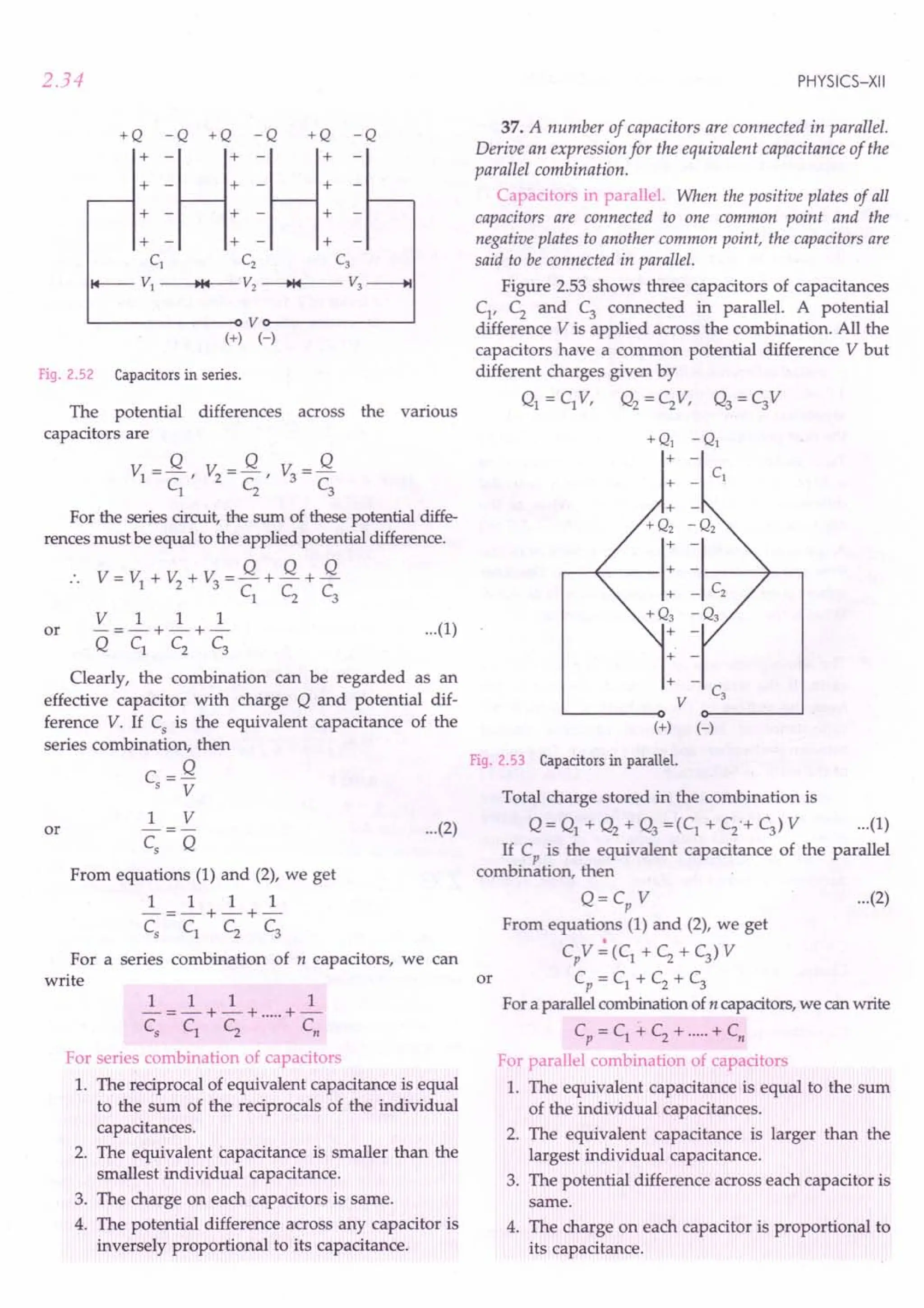
![ELECTROSTATIC POTENTIAL AND CAPACITANCE
iliiiiiiiiiiiiiiiiiii~LE~xampleS_b_a.s__e_d_O_n -----'
Formulae Used
1. In series combination,
1 1 1 1
-=-+-+-+ ...
C
s
c,. CZ C;
2. In parallel combination, Cp
= c,. + CZ + C; + ...
3. In series combination, charge on each capacitor is
same (equal to the charge supplied by battery) but
potential differences across the capacitors may be
different.
4. In parallel combination, potential difference on
each capacitor is same but the charges on the capa-
citors may be different.
Units Used
Capacitances are in farad, potential differences in
volt and charges in coulomb.
Example 43. Two capacitors of capacitance of 6 !IF and
12 !IF are connected in series with a battery. The voltage
across the 6 !IF capacitor is 2 V. Compute the total battery
voltage. [CBSE 00 06]
Solution. As the two capacitors are connected in
series, the charge on each capacitor must be same.
Charge on 6!lF = Charge on 12 !IF
capacitor capacitor
or 6 !IF x 2 volt = 12 !IF x V volt
6x2
:. PD. across 12 !IF capacitor = -- = 1volt
12
Battery voltage = VI + V2 =2 V + 1 V = 3 V.
Example 44. Two capacitors of capacitances 3!lF and
6 !IF, are charged to potentials of2 V and 5 V respectively.
These two charged capacitors are connected in series. Find
the potential across each of the two capacitors now.
[CBSE Sample Paper 04]
Solution. Total charge on the two capacitors
=CIVI + C2V2 =(3x2 +6x 5)!lC=36!lC
In series combination, charge is conserved.
.. Charge on either capacitor,
q = 36!lC
Potential on 3 !IF capacitor =!L = 36 !lC = 12 V
CI 3!lF
Potential on 6 !IF capacitor =!L = 36 !lC = 6 V.
C2
6!lF
Example 45. Two capacitors have a capacitance of 5!lF
when connected in parallel and 1.2 !IF when connected in
series. Calculate their capacitances.
2.35
Solution. Let the two capacitances be CI !IF and C2
!IF.
In parallel, Cp = CI + C2
= 5 !IF
CC
Cs
= 1 2 = 1.2 !IF
CI + C2
CI(5 - CI) = 1.2
5
2
CI - 5CI + 6 = 0
Hence, CI = 2 or 3!lF
:. The capacitances are of 2!lF and 31lF.
Example 46. Three capacitors of equal capacitance, when
connected in series have net capacitance CI
, and when
connected in parallel hque net capacitance C2. What is the
value of CI / C2 ?
Solution. Let C = capacitance of each capacitor.
For series combination,
In series,
or
or
1 1 1 1 3
-=-+-+-=- or
CI C C C C
For parallel combination,
CI_C 1_1
C
2
-3"'3C-9
Example 47. In Fig. 2.54, each of the uncharged capacitors
has a capacitance of25 !IF. What charge will flow through
the meter M when the switch 5 is closed ?
C2
= C + C + C =3C
r~
4200 V
l~_I J Ie
Fig. 2.54
Solution. As the three capacitors are connected in
parallel, their equivalent capacitance is
Cp = C + C + C =3C =3 x 25!lF =75!lF
V= 4200 V
Charge, q = Cp
V = 75 x 10-6 x 4200
= 315 x 10- 3 C = 315 me
Example 48. Calculate the charge supplied by the battery
in the arrangement shown in Fig. 2.55.
Fig. 2.55
10V](https://image.slidesharecdn.com/slaroraclass12thphysicsbyrockytrickster-250318042948-c8b51a5a/75/SL-ARORA-CLASS-12TH-PHYSICS-BY-ROCKY-TRICKSTER-pdf-126-2048.jpg)
![2.36
Solution. The given arrangement is equivalent to
the arrangement shown in Fig. 2.56.
c1 = 5 J.1f
II
+11 -
II
+11
Cz = 6 J.1f
+ I -
I
10V
Fig. 2.56
Clearly, the two capacitors are connected in parallel.
Their equivalent capacitance is
C = C1 + C2 = 5 + 6 = 11~F
Charge supplied by the battery is
q = CV = 11~F x 10 V = 110 J..Ic.
Example 49. Three capacitors C1
, C2
and C3
are connected
to a 6 V battery, as shown in Fig. 2.57. Find the charges on
the three capacitors.
I
Fig. 2.57
Solution. The given arrangement is equivalent to
the arrangement shown in Fig. 2.58(a).
6V
+ -
(a)
C1 = 10IlF C' = 10IlF
C:J
6V
(b)
Fig. 2.58
PHYSICS-XII
Clearly, C2
and C3
are in parallel. Their equivalent
capacitance is
C' = C2
+ C3
= 5 + 5 = 10 ~F
Now C1
and C' form a series combination, as
shown in Fig. 2.58(b). Their equivalent capacitance is
C = C1 C = 10 x 10 = 5 ~F
C1
+ C 10 + 10
Charge drawn from the battery,
q = CV = 5 ~Fx 6 V =30 ~C
Charge on the capacitor C1
= q = 30 ~C
Charge on the parallel combination of C2 and
C3 =q=30 ~C
As C2
and C3
are equal, so the charge is shared
equally by the two capacitors.
30
Charge on C2 = charge on C3 = - = 15 ~C
2
Example 50. Find the equivalent capacitance of the
combination of capacitors between the points A and B as
shown in Fig. 2.59. Also calculate the total charge that flows
in the circuit when a 100 V battery is connected between the
points A and B. [CBSE D 02]
40 J.1f 60 J.1f
A o-------i ~
I ~J.1f
lOp!' ~ 6Op!'
L---~----------~---oB
Fig. 2.59
Solution. Here three capacitors of 60 ~F each are
connected in series. Their equivalent capacitance C1 is
given by
1 1 1 1 3 1
-=-+-+-=-=-
• C1 60 60 60 60 20
or C =20 ~F
The given arrangement now reduces
equivalent circuit shown in Fig. 2.60(a)
40 J.1f
(,)Ao-i::-Lo ,I 1,0,'
T T T
to the
(b)
40 IlF 40 IlF
A OI----IIf---IIf---O B
Fig. 2.60](https://image.slidesharecdn.com/slaroraclass12thphysicsbyrockytrickster-250318042948-c8b51a5a/75/SL-ARORA-CLASS-12TH-PHYSICS-BY-ROCKY-TRICKSTER-pdf-127-2048.jpg)
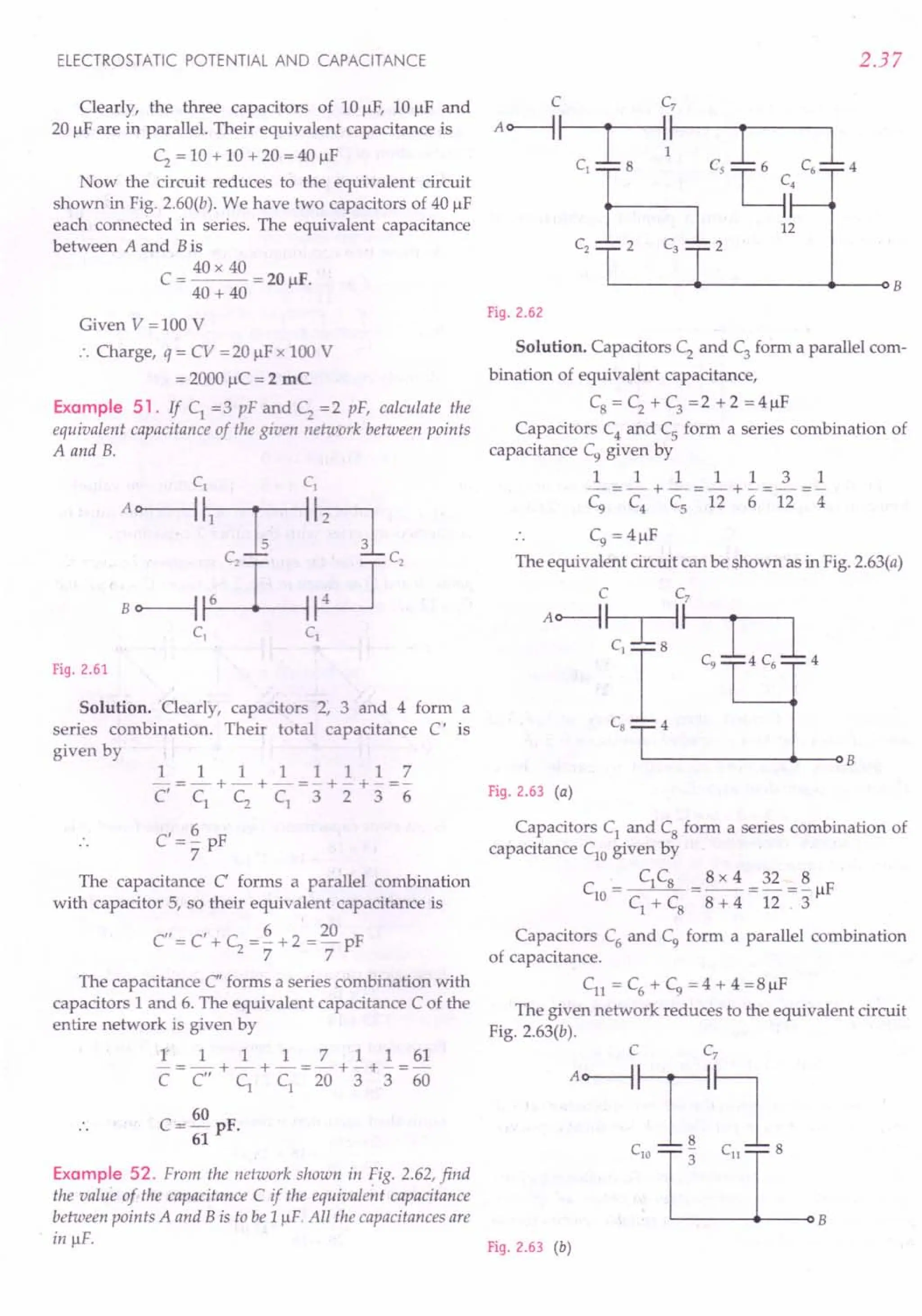
![2.38
Again, capacitors C7
and Cn form a series combi-
nation of capacitance C12
given by
C
_ C7 x Cn _1 x 8 _ 8 IF
12 - - -- r
C7
+ Cn 1 + 8 9
Now ClO
and C12
form a parallel combination of
capacitance C13
as shown in Fig. 2.63(c).
8 8 32
C13 = ClO + C12 = 3" + 9' = 9JlF
C
A~~
clOLL~ C
12
~
3 9
B
Fig. 2.63 (c)
Finally, the capacitors C and C13
form a series com- or
bination of capacitance 1 JlF as shown in Fig. 2.63(d).
C C13
A~~~B
32
9
Fig. 2.63 (d)
1 1 9
-=-+-
1 C 32
or
32
C=-JlF.
23
Example 53. Connect three capacitors of3JlF,3 JlF
and 6 JlF such that their equivalent capacitance is 5 JlF.
Solution. Capacitors connected in parallel have
maximum equivalent capacitance.
Cmax = 3 + 3 + 6 = 12 JlF
Capacitors connected in series have minimum
equivalent capacitance.
1 1 1 1 5
--=-+-+-=-
Cmin 3 3 6 6
6
or Cmin = - = 1.2 JlF
5
The required equivalent capacitance of 5 JlF lies
between Cmax and·Cmin. So
3x6
5 JlF = 3 JlF + 2 JlF = 3 JlF + - JlF
3+6
So we should connect the series combination of3 JlF
and 6 JlF capacitors in parallel with the third capacitor
of 3 JlF.
Example 54.Seven capacitors, each of capacitance 2 JlFare
to be connected in a configuration to obtain an effective
capacitance of 10 / 11 JlF. Suggest a suitable combination to
achieve the desired result. [lIT 90]
PHYSICS-XII
Solution. Suppose a parallel combination of n
capacitors is connected in series with a series
combination of (7 - n) capacitors.
Capacitance of parallel combination, C1
=2n JlF
2
Capacitance of series combination, C2
= -- JlF
7-n
As these two combinations are in series, so
C = 10 F
5 11 Jl
1 1 1 11 1 7-n
But -=-+- -=-+--
~ ~ ~ 10 2n 2
Multiplying both sides by 10 n, we get
11n = 5 + 3Sn - 5n2
Sn2
-24n-S =0
or
(n - S)(5n + 1) = 0
n = 5 [Rejecting -ve value]
Hence parallel combination of 5 capacitors must be
connected in series with the other 2 capacitors.
Examp e 55 Find the equivalent capacitance between the
points P and Q as shown in Fig. 2.64. Given C = 18 JlFand
C1 = 12 JlF. REC 97]
:&lliDc
c E C B C
Fig 2.64
Equivalent capacitance between points F and B is
18 x 18 + 18 = 27 F
18 + 18 Jl
Equivalent capacitance between points A and B is
18 x 27
12 + -- = 12 + 10.8 =22.8 "'-23 JlF
18 +27
Equivalent capacitance between points A and E is
23 x 18 + 18 = 28 F
23 + 18 Jl
Equivalent capacitance between points 0 and E is
28 x 18 + 12 = 23 F
28 + 18 Jl
Equivalent capacitance between points 0 and Q is
23 x 18 + 18 = 28 F
23 + 18 Jl
Equivalent capacitance between points P and Q is
28 x 18 = 11 F.
28 + 18 Jl](https://image.slidesharecdn.com/slaroraclass12thphysicsbyrockytrickster-250318042948-c8b51a5a/75/SL-ARORA-CLASS-12TH-PHYSICS-BY-ROCKY-TRICKSTER-pdf-129-2048.jpg)
![ELECTROSTATIC POTENTIAL AND CAPACITANCE
Example 56. Four capacitors are connected as shown in
the Fig. 2.65. Calculate the equivalent capacitance between
the points X and Y. [CBSE D 2000]
x e 1 ,1!~~hj;i~Y
Fig. 2.65
Solution. Clearly, the first plate of 2 IlF capacitor,
the second plate of 3 IlF capacitor and the first plate of
5 IlF capacitor are connected to the point A On the
other hand, the second plate of 2 IlF capacitor, the first
plate of 3 IlF capacitor and the second plate of 5 IlF
capacitor are connected to the point B.Thus the capa-
citors of 2 IlF, 3 IlF and 5 IlF are connected in parallel
between points A and B, as shown in the equivalent
circuit diagram of Fig. 2.66.
21lF
Xo---A+----II----+-B---I~y
10 JlF
Fig. 2.66
Total capacitance of the parallel combination of
capacitances 21lF, 3 IlF and 5 IlF is
C=2+3+5=IOIlF
As shown in Fig. 2.67, this parallel combination is
in series with capacitance of 10 1lF.
x o>-----II--~II--Oy
Fig. 2.67
Equivalent capacitance between X and Y
= 10 x 10 = 5 F.
10 + 10 Il
Example 57 .Five capacitors of capacitance 10 IlF each are
connected with each other, as shown in Fig. 2.68. Calculate
the total capacitance between the points A and C.
C4
A$~~c
Fig. 2.68
2.39
Solution. The given circuit can be redrawn in the
form of a wheatstone bridge as shown in Fig. 2.69.
B
c'4~
A~~rc
C
Fig. 2.69
As C1 = C2 = C4 = Cs '
C C
Therefore, -.l = --.! .
C2
c,
Thus the given circuit is a balanced wheatstone
bridge. So the potential difference across the ends of
capacitor C3 is zero. Capacitance C3 is ineffective. The
given circuit reduces to the equivalent circuit shown in
Fig. 2.70(a).
Fig. 2.70 (a)
Capacitors C1 and C2 form a series combination of
equivalent capacitance C6
given by
C = C1 x C2 = 10 x 10 = 5 IlF
6 C1 + C2 10 + 10
Similarly, C4
and Cs form a series combination of
equivalent capacitance C7 given by
C = C4 x Cs = 10 x 10 = 5 IlF
7 C4 + C
s 10 + 10
As shown in Fig. 2.70(b), C6 and C7 form a parallel
combination. Hence the equivalent capacitance of the
network is given by
C = C6
+ C7
= 5 + 5 = 10 IlF.
C6
A~~C
Fig. 2.70 (b)](https://image.slidesharecdn.com/slaroraclass12thphysicsbyrockytrickster-250318042948-c8b51a5a/75/SL-ARORA-CLASS-12TH-PHYSICS-BY-ROCKY-TRICKSTER-pdf-130-2048.jpg)
![2.40
Example 58. There are infinite number of capacitors, each
of capacitance I/-1F. Thelj are connected in rows, such that
the number of capacitors in thefirst row, second row, third
row, fourth row, are respectively 1, 2, 4, 8, ..... The rows of
these capacitors are then connected between points A and B,
as shown in Fig. 2.71. Determine the equivalent capacitance
of the network between the points A and B.
1 IlF
A B
Fig. 2.71
Solution. Let Cl, C2, Cy C4, ..... be the effective or
capacitances of the capacitors of first row, second row,
third row, fourth row, ..... respectively. Then
Cl = IIJF
1xII
C2
= -- =- /-IF
1+ 1 2
11111
-=-+-+-+-=4
C3 1 1 1 1
1
C3 = 4" /-IF
Similarly, C4
= .!./-IF,and so on.
8
As these rows are connected in parallel between
points A and B,so the equivalent capacitance between
points A and Bis
1 1 1
C = Cl + C2 + C3 + C4 + ..... =1 + - + - + - + .....
2 4 8
This is an infinite geometric progression with first
term a = 1 and common ratio r = 1/2. Hence
a 1
C=-=--=2/-1F.
l-r 1-1/2
Example 59. Find the equivalent capacitor of the ladder
(Fig. 2.72) between points A and B.
21lF 21lF
A~T,~T,~~-l"~
T T T Ihh_
Bo
Fig. 2.72
PHYSICS-XII
Solution. Let C be the equivalent capacitance of the
infinite network. It consists of repeating units of two
capacitors of I/-1F and 2 /-IF.The addition of one such
more unit will not affect the equivalent capacitance.
But then the network would appear as shown in
Fig. 2.73.
Fig. 2.73
The equivalent capacitance of the new arrangement
must be equal to C.
C=I+
2xC
2+C
or C2
- C -2 = 0
C = 2 /-IF or - 1 /-IF
As the capacitance cannot be negative, so the
equivalent capacitance of the ladder is 2/-1F.
Example 60. If Cl =20 /-IF, C2 =30 /-IF and C3 =15 /-IF
and the insulated plate of Cl
be at a potential of90 V, one
plate of C3 being earthed. What is the potential difference
between the plates of C2' three capacitors being connected in
series? [CBSE OD 15]
Solution. Here Cl = 20/-lF, C2 =30 ~lF, C3 = 15 /-IF,
V=90V
Fig. 2.74
The equivalent capacitance C of the series com-
bination is given by
11111113
-=-+-+-=-+-+-=-
C Cl C2 C3 20 30 15 20
C = 20 /-IF
3
Total potential difference =90 -0 =90 V
:. Total charge,
q = CV = 20 x 10-6.90 =600 x 10- 6 C
3
PD. between the plates of capacitor C2
is
V =..!L = 600 x 10-
6
C = 20 V.
2 C
2
30 x 10-6 F](https://image.slidesharecdn.com/slaroraclass12thphysicsbyrockytrickster-250318042948-c8b51a5a/75/SL-ARORA-CLASS-12TH-PHYSICS-BY-ROCKY-TRICKSTER-pdf-131-2048.jpg)
![ELECTROSTATIC POTENTIAL AND CAPACITANCE
Example 61. In the circuit shown in Fig. 2.75, if the point'
C isearthed and point A isgiven a potential of + 1200 V,find'
the charge on each capacitor and the potential at the point B.
C2
cb-[J
12000V I 4~F
A 3~F B 3
2 ~F
v=O
c
Fig. 2.75
Solution. Capacitors C; and C3 form a parallel com-
bination. Their equivalent capacitance is
C' = C2
+ C3
= (4 + 2) J.lF= 6 J.lF
Now Cl and C' form a series combination, there-
fore, the equivalent capacitance of the entire network is
CC' 3 x 6
C = C + C' = 3 + 6 = 2 J.lF
The charge on the equivalent capacitor is
q = CV =2 x 10-6 x 1200 C =2.4 x 10⁻³ C
This must be equal to the charge on C, and also the
sum of the charges on C2
and C3• Thus
V _ v: = -.:L = 2.4 x 10-
3
=800 V
A B C
l
3 x 10⁻⁶
VA = 1200 V
.. VB = 1200 -800 = 400 V
Hence Ve - VB = 400 -0 = 400 V
q2 = C2 (Ve - VB) = 4 x 10-6 x 400 C ==
1.6 x 10⁻³
C
q3 ==C3
(Ve - VB) =2 x 10-6 x 400 C = 0.8 x 10⁻³
C
ql ==q = 2.4 x 10⁻³C.
Example 62. A network of four 10 J.lF capacitors is
connected to a 500 V supply as shown in Fig. 2.76. Deter-
mine (a) the equivalent capacitance of the network, (b) the
charge on each capacitor. [NCERT]
+q -q
Brlhc
_q .L.+ c,-" ~+q
CI C3
+q ++++ -----q
+q' _q'
+
A
+ D
+
+
C4
SOOV
Fig. 2.76
2.41
Solution. (a) In the given network, Cl' C2 and C3 are
connected in series. Their equivalent capacitance C I is
given by
11111113
-==-+-+-==-+-+-=-
C' Cl C2 C3 10 10 10 10
C'== 10 J.lF
3
Now C' and C4 form a parallel combination. There-
fore, the equivalent capacitance of the whole network is
I 10 40
C= C + C4 ==-+ 10 =-J.lF =13.3 J.lF.
3 3
or
(b) It is clear from Fig. 2.76 that the charge on each
of the capacitors Cl, C2
and C3
is same. Let it be q. Let
the charge on C4 be q'.
•. P.D. across AB,
or
P.D. across BC,
P.D. across CD,
But
or
==
1.7x 10⁻³ C
Also, P.D. across AD='£ =500 V
C4
•. q'=500xC4==500xl0J.lC
= 5000 x 10-6 C ==
5 x 10⁻³ C.
Example 63. Four capacitors Cl' C2
' C3 and C4 are con-
nected to a battery of12 V, as shown in Fig. 2.77. Find the
potential difference between the points A and B.
CI = 8 ~F C2 = 4 ~F
I 1 I
+ -
12 V
Fig. 2.77](https://image.slidesharecdn.com/slaroraclass12thphysicsbyrockytrickster-250318042948-c8b51a5a/75/SL-ARORA-CLASS-12TH-PHYSICS-BY-ROCKY-TRICKSTER-pdf-132-2048.jpg)
![2.42
Solution. Let VA be the potential at point A and VB
that at B. Then
P.D. across C1 = 12 - VA
P.D. across C2
= VA -0 = VA
P.D. across C3 = 12 - VB
P.D. across C4 = VB -0 = VB
As the capacitors C1 and C2 are connected in series, so
ql = q2
or C1 (12 - VA) = C2VA
or 8 (12 - VA) = 4 VA
or VA =8 V
Again, the capacitors C3
and C4
are connected in
series, so
q3 = q4
or C3
(12 - VB) = C4 VB
or 3 (12 - VB) = 6 VB
or VB = 4V
The potential difference between the points A and Bis
VA - VB = 8 - 4 = 4 V.
Example 64. Five identical capacitor plates, each of areaA
are arranged such that the adjacent plates are at distance d
apart. The plates are connected to a source of emf V, as
shown in Fig. 2.78. Find the charges on the various plates.
[lIT 84]
1 2 3 4 5 ..;;;;..v
+
A
Fig. 2.78
Solution. As shown in Fig. 2.79, the given network
is equivalent to three parallel-plate capacitors con-
nected in parallel.
Their capacitances are
EO A 2 EO A and EO A
-d-' d d
A
The p.d. across each V
capacitor is V. + -
As Fig. 2.79
Charge = Capacitance x p.d.
PHYSICS-XII
So charges on various plates are
_ + EO A V __ 2 EO A V
ql - d' q2 - d
_ 2 EO AV _ 2 EO AV _ EO AV
q3 - + d ' q4 - - d ' qs - + -d- .
Example 65. For the network shown in Fig. 2.80, find the
potential difference between points A and B, and that bet-
ween Band C in the steady state.
3flF IJlF
3~~
Ion
20n
A c>----'VJ'r--+-:-I1111 r---<lC
100V
Fig. 2 80
Solution. The two capacitors of 3 flF and 3 flF on the
left side of the network are in parallel, their equivalent
capacitance = 6 flF
The two capacitors of 1flF and 1flF on the other side
of the network are also in parallel, their equivalent
capacitance = 2 flF. So the given network reduces to the
equivalent circuit shown in Fig. 2.81.
~
6 flF 2 flF
Ion
. 20n 100V
A<r--'vvv--+-:-11111 _
C
Fig. 2.81
In the steady state, when all the capacitors are
charged, there is no current in the circuit. So there is no
potential drop across any resistance. Hence
p.d. across 1uf capacitor
= p.d. between points A and C = 100 V
As 6 flF and 2 flF capacitances are in series, the p.d.
of 100 V is divided between them in the inverse ratio of
their capacitances i.e., in the ratio 2 : 6 or 1 : 3.
1
VAB = p.d. across 6 flF = 4" x 100 = 2S V
3
VBC = p.d. across 2 flF= 4" x 100 = 7S V.](https://image.slidesharecdn.com/slaroraclass12thphysicsbyrockytrickster-250318042948-c8b51a5a/75/SL-ARORA-CLASS-12TH-PHYSICS-BY-ROCKY-TRICKSTER-pdf-133-2048.jpg)
![ELECTROSTATIC POTENTIAL AND CAPACITANCE
~rOblems For Practice
1. Two capacitors have a capacitance of 51lF when
connected in parallel and 1.2IlFwhen connected in
series. Calculate their capacitances.
(Ans. 21lF,31lF)
2. Two capacitors of equal capacitance when
connected in series have net capacitance C;, and
when connected in parallel have net capacitance c;..
What is the value of C; / c;. ? [CBSE D 93CI
(Ans. C; / c;. = 1/4)
3. Three capacitors of capacity 1, 2 and 31lF are
connected such that second and third are in series
and the first one in parallel. Calculate the resultant
capacity. (Ans. 2.2 IlF)
4. The capacities of three capacitors are in the ratio
1 : 2 : 3. Their equivalent capacity in parallel is
greater than the equivalent capacity in series by
60/11 pF. Calculate the individual capacitances.
(Ans. 1 pF, 2 pF, 3 pF)
5. The equivalent capacitance of the combination
between A and B in Fig. 2.82 is 41lF.
20 f.1F
~----~II---H--;
C
Fig.2.82
(i) Calculate capacitance of the capacitor C.
(ii) Calculate charge on each capacitor if a 12 V
battery is connected across terminals A and B.
(iii) What will be the potential drop across each
capacitor? [CBSE D 091
[Ans. (i) 51lF (ii) 48 IlC (iii) 2.4 V, 9.6 Vj
6. How would you connect 8, 12 and 241lF capacitors
to obtain (i) minimum capacitance (ii) maximum
capacitance? If a potential difference of 100volt is
applied across the system, what would be the
charges on the capacitors in each case?
[Ans. (i) In series, Cmin = 41lF,q = 41lC,
(ii) In parallel, Crnax
= 44IlF, ql = 8001lC,
q2 = 1200IlC, q3 = 24001lC]
7. Calculate the capacitance of the capacitor in Fig.2.83,
if the equivalent capacitance of the combination bet-
ween A and B is 151lF. [CBSE D 941
(Ans. 601lF)
Fig.2.83
2.43
8. In the combination of four identical capacitors shown
in Fig. 2.84, the equivalent capacitance between
points P and Q is 1 IlF. Find the value of each
separate capacitance. (Ans. 41lF)
Fig.2.84
9. Find the equivalent capacitance of the combination
shown in Fig. 2.85 between the points A and B.
L l (Ans.c;+~J
A~~B ~+~
C1-r= C2=r-
Fig.2.85
10 For the network shown in Fig. 2.86, calculate the
equivalent capacitance between points A and B.
(Ans.6IlF)
Fig.2.86
11. Calculate the capacitance of the capacitor C in
Fig. 2.87. The equivalent capacitance of the combi-
nation between P and Q is 30 1lF. [CBSE OD 95]
(Ans. 60IlF)
C 20 f.1F
P~~~--4~--~S--~Q
Fig.2.87
12. Calculate the equivalent capacitance between points
A and B of the combination shown in Fig. 2.88.
A~~~"~:F)
IIlF IIlF
Fig.2.88](https://image.slidesharecdn.com/slaroraclass12thphysicsbyrockytrickster-250318042948-c8b51a5a/75/SL-ARORA-CLASS-12TH-PHYSICS-BY-ROCKY-TRICKSTER-pdf-134-2048.jpg)
![2.44
13. Find the equivalent capacitance between points A
and B for the network shown in Fig. 2.89.
C1 Cz ( Ans. ~ JlF)
"T"
A C3 1 J!F B
Fig.2.89
14. Calculate the equivalent capacitance between the
points A and B of the circuit given below.
C C [CBSE F 95]
1 z 28
Ao----1~~ (Ans.-JlF)
4J!F r~ •..
:J!Fr~ ~
C6I'"' C'W'
C,1'"' "lB
Fig.2.90
15. A network of six identical capacitors, each of value
Cis made, as shown in Fig.2.91.Find the equivalent
capacitance between the points A and B.
(Ans. 4C/ 3)
A 0---,:--1
I----'--<l B
Fig.2.91
16. Find the equivalent capacitance between the points
A and B of the network of capacitors shown in
Fig. 2.92. (Ans. 1JlF)
Fig.2.92
17. Find the capacitance between the points A and B
of the assembly shown in Fig. 2.93.
(Ans. 2.25JlF)
PHYSICS-XII
Fig.2.93
18. Find the resultant capacitance between the points X
and Y of the combination of capacitors shown in
Fig. 2.94. [Haryana 01]
(Ans. 2.5JlF)
5J!F
Fig.2.94
19. The outer cylinders of two cylindrical capacitors of
capacitance 2.2JlFeach are kept in contact and the
inner cylinders are connected through a wire. A
battery of emf 10 V is connected, as shown in
Fig. 2.95.Find the charge supplied by the battery to
the inner cylinders. (Ans. 44 JlC)
lOV
Fig.2.95
20. In Fig. 2.96, C1 = 1JlF,C2 = 2 JlFand c, = 3 JlF.Find
the equivalent capacitance between points A and B.
(Ans.6JlF)
A 0---< >---QB
Fig.2.96
21. Four capacitors of equal capacitances are con-
nected in series with a battery of 10 V, as shown in](https://image.slidesharecdn.com/slaroraclass12thphysicsbyrockytrickster-250318042948-c8b51a5a/75/SL-ARORA-CLASS-12TH-PHYSICS-BY-ROCKY-TRICKSTER-pdf-135-2048.jpg)
![ELECTROSTATIC POTENTIAL AND CAPACITANCE
Fig. 2.97. The middle point B is connected to the
earth. What will be the potentials of the points A
and C? (AnS. VA = + 5 V, Vc = - 5 V)
lOV
J;~:l
"
Fig. 2.97
22. Determine the potential difference across the plates
of each capacitor of the network shown in Fig. 2.98.
Take Ez > fl·
(
Ans. v: = (Ez - fl) c; r v: = (Ez - fl) c;.J
1 c;.+c; 2 c;.+c;
Fig. 2.98
23. Find the potential difference between the points A
and B of the arrangement shown in Fig. 2.99.
(Ans. - 8 V)
Fig. 2.99
24. Determine the potential difference VA - VB bet-
ween points A and B of the circuit shown in
Fig. 2.100.Under what condition is it equal to zero?
Po--f---l 1-----4t--- I---t----o Q
v
Fig. 2.100
2.45
25. A variable capacitor has n plates and the distance
between two successive plates is d.. Determine its
capacitance. (Ans. C = (n - ~ Eo A J
26. A network of four capacitors each of 12 JlF
capacitance is connected to a 500 V supply as
shown in Fig. 2.101. Determine
(a) equivalent capacitance of the network, and
(b) charge on each capacitor. [eBSE OD 10]
[Ans. (a) 16 JlF (b) ql = q2 = q3 =2000 JlC,
q4 =6000 flq
Fig. 2.101
27. For the network shown in Fig. 2.102, compute
3J.lF 3J.lF 3J.lF
'~~,~~
bo--1~~~
3J.lF 3J.lF 3J.lF
Fig. 2.102
(i) the equivalent capacitance between points a
and b.
(ii) the charge on each of the capacitors nearest to a
and b when Vab = 900V.
(iii) V cd r when Vab = 900 V.
[Ans. (i) 1 JlF(ii) 900 JlC (iii) 100 Vj
HINTS
1. Proceed as in Example 45 on page 2.35.
2. Proceed as in Example 46 on page 2.35.
2x3
3. C = 1+ -- = 2.2 JlF.
2+ 3
4. Let the capacitances be C, 2 C and 3 C. Then
Cp = C + 2 C + 3 C= 6 C
1 1 1 1 11 6C
-=-+-+-=- or C =-
Cs C 2C 3C 6C s 11
60 6C 60
Given Cp - Cs = 11pF or 6 C - 11= 11 pF
or C= 1pF
So the individual capacitances are 1 pF, 2 pF and
3 pF.](https://image.slidesharecdn.com/slaroraclass12thphysicsbyrockytrickster-250318042948-c8b51a5a/75/SL-ARORA-CLASS-12TH-PHYSICS-BY-ROCKY-TRICKSTER-pdf-136-2048.jpg)
![2.46
5. (i) As 20 /IF capacitor and capacitor C are in series,
their equivalent capacitance is
C = Cx20
AB C+ 20
20C
or 4/lF=--
C+20
or 4C+ 80 = 20C
or C = 5/lF.
(ii) Charge on each capacitor,
q = CAB V = 4/lF x12V = 48 /lC
(...) P D F . q 48/lC V
III . . on 20/l capacitor =-- =-- =2.4
20/lF 20/lF
q 48/lC
P.D. on capacitor C = - = -- = 9.6 V.
C 5/lF
6. (i) For minimum capacitance, the three capacitors
must be connected in series. Then
1 1 1 1 1
-- = - + - + - = - or Cmin = 4/lF.
Cmin 8 12 24 4
(ii) For maximum capacitance, the three capacitors
must be connected in parallel. Then
Cmax = 8 + 12 + 24 = 44/lF.
(iii) In series combination, charge is same on all
capacitors.
q = CV = 4/lF x 100V = 4/lC.
In parallel combination, charges on the
capacitors are
1ft = C1
V = 8/lF x 100V = 800/lC
q2 = C;V = 12/lF x 100 V = 1200/lC
q3 = C;V = 24/lF x 100 V = 2400/lc.
7. The combined capacitance of the parallel com-
bination of two 10/IFcapacitors is 20 /IF.This com-
bination is connected in series with capacitance C.
1 1 1 1 1 1 4-3 1
.. -+-=- or -=---=--=-
20 C 15 C 15 20 60 60
or C = 60/lF.
8. All capacitors are in series.
4 1
- -- or C = 4 /IF.
C l/lF
9. C=~+~+~=~+ 2C1C;.
C1+C; C1+C; C1+C;
1 1 1 1 1
10. C ="'9+ "'9
+ "'9
= '3' C = 3/lF
C = 3/lF + C = 3/lF + 3/lF = 6/lF.
1 1 1
11. - + - = - :. C = 60/lF.
C 60 30
1 1 112
12. - = -- + - + -- = - .. C = 0.5 /IF.
C 1+1 1 1+1 1
PHYSICS-XII
13. C1and ~ are in parallel between points A and D. So
the equivalent capacitance between A and D is
C'=C1+~=1+1=2/lF
The given network now reduces to the equivalent
circuit shown in Fig. 2.103.Between points A and B,
now C and C; are in series and C4
in parallel. Hence
the equivalent capacitance between A and B is
CZ
H~
C'~C~B
2 !iF
CC; 2x1 8
C = -- + C = -- + 2 = - /IF.
C+C; 4 2+1 3
Fig. 2.103
14 Capacitors C;, ~ and C4
are connected in series,
their equivalent capacitance ~ is given by
11111111
-=-+-+-=-+-+-=-
c, C; c, C4
4 2 4 1
~ = l/lF
Also, CSand C6are in series, the equivalent capa-
citance is
CSxC6 2x4 4
Cs =--=-=-/IF
CS
+C6 2+43
~ and Csform a parallel combination ofcapacitance,
4 7
~=~+Cs=I+-=-/lF
3 3
Now C1and ~ form a series combination. The equi-
valent capacitance C between A and B is given by
1 1 1 1 3 19
- = - + - = - + - = - or
CC1 ~4728
28
C =-/IF.
19
15. The equivalent network is shown in Fig. 2.104.
Fig. 2.104
Clearly, the equivalent capacitance
= [2 Cand C in series] II [Cand 2 C in series]
2C x C C x2C 4C
=---+---=-.
2C+ C C+ 2C 3
16. Two 2/lF capacitors at the left side of the network
are in series. Their equivalent capacitance is
2x2
C =-- =l/lF
s 2 + 2](https://image.slidesharecdn.com/slaroraclass12thphysicsbyrockytrickster-250318042948-c8b51a5a/75/SL-ARORA-CLASS-12TH-PHYSICS-BY-ROCKY-TRICKSTER-pdf-137-2048.jpg)
![ELECTROSTATIC POTENTIAL AND CAPACITANCE
The capacitance Cs and the next capacitor of 1J..lF
are
in parallel. Their equivalent capacitance is
Cp = 1+ 1= 2J..lF
Proceeding in this way, we finally get two 2 J..lF
capacitors connected in-series.
·. Equivalent capacitance between A and B
2x2
=--=lJ..lF.
2+ 2
17. The given arrangement is a balanced wheatstone
bridge. Proceed as in Example 57 on page 2.39.
18. The arrangement between the points A and B is a
balanced wheatstone bridge. Proceeding as in
Example 57, we find that the equivalent capacitance
between A and Bis
C' = 5J..lF
Now the capacitor C' and the left out capacitor of
5 J..lFare in series. The equivalent capacitance
between points X and Y will be
C'x5 5x5
C = -,- = -- = 2.5IlF.
C +5 5+5
19. The two capacitors are connected in parallel
·. C = 2.2 + 2.2 = 4.4J..lF
Charge, q = CV = 4.4 J..lF
x 10 V = 44 J..lc.
20. The three capacitors are connected in parallel
between points A and B.
·. C = ~ + Cz + ~ = 1+ 2 + 3 = 6 J..lF.
21. Here VB = O. As the capacitances are equal on the
two sides of point B,
.. VA - VB = VB - Vc
or VA + VC = 2 VB = 0
But VA - Vc = 10 V
.. VA = + 5 V and Vc = - 5 V.
22. Let charge q flow across the capacitor plates until
the current stops. In a closed circuit,
L 6V = 0
f1 +!L-E2+!L=0
~ Cz
q [ +CzCz J = E2 - f1
(E2-f1)~Cz
q= ~+Cz
P.D. across plates of ~ =!L = (E2 - f1) Cz
~ ~+Cz
PD. across plates of Cz =!L = (E2 - f1) ~ .
Cz ~+Cz
or
or
or
23. The given arrangement is equivalent to the circuit
shown in Fig. 2.105.
2.47
Fig. 2.105
Proceeding as in the above problem 22, we get
_ (E2 - f1) ~Cz
q- ~+Cz
P.D. across the plates of ~,
v =!L=(E2-f1)Cz=(12V-24V)4J..lF =-SV
1 ~ ~+Cz 2J..lF+4J..lF
24. Suppose the charge ql flows in the upper branch
and 'h in the lower branch. Then
V = ql [~ + ~ J or
Also, V = q2 [.2. + .2.J
c, C
4
V~C4
or q2 = ~ + C
4
:. VA - VB = (V
Q
- VB) -(V
Q
- VA) = i£. _!!L
C4
Cz
Putting the values of ~ and q2' we get
V -V -~-~
A B-~+C4 ~+Cz
_ V [ Cz~ - ~C4 ]
(~ + Cz)(~ + C4)
For VA - VB = 0, we have
£L= ~
Cz C4
25. The given arrangement is equivalent to (n -1)
capacitors joined in parallel.
. . C = (n - 1) Eo A .
d
12J..lF
26. (a) ~23 = -3- = 4 J..lF
Ceq = ~23 + C4
= 4 + 12 = 16 J..lF.
(b) ql = q2 = q3 = ~23 V = 4 J..lF
x500V = 2000 J..lC
q4 = C4
V = 12 J..lF
x500 V = 6000 uc
27. (i) Three 3J..lF
capacitors in series have equivalent
capacitance = 1J..lF.The combination is in
parallel with 2 JlF capacitor.
•. Equivalent capacitance between.c and d
=1+2=3J..lF
or](https://image.slidesharecdn.com/slaroraclass12thphysicsbyrockytrickster-250318042948-c8b51a5a/75/SL-ARORA-CLASS-12TH-PHYSICS-BY-ROCKY-TRICKSTER-pdf-138-2048.jpg)
![2.48
The situation is repeated for points e and f
Hence there are three 31lF capacitors in series
between points a and b. Equivalent capacitance
between a and b = 11lF.
(ii) Potential drop of 900 V across a and b is equally
shared by three 31lF capacitors.
Hence charge on each capacitor nearest to a
and b
= 300 x 3 = 900 IlC
(iij) Potential drop of 300 V across e and f is equally
shared by 31lF capacitors.
Hence Vcd = 100 V.
2.24 ENERGY STORED IN A CAPACITOR
38. How does a capacitor store energy ? Derive an
expression for the energy stored in a capacitor.
Energy stored in a capacitor. A capacitor is a device
to store energy. The process of charging up a capacitor
involves the transferring of electric charges from its
one plate to another. The work done in charging the
capacitor is stored as its electrical potential energy. This
energy is supplied by the battery at the expense of its
stored chemical energy and can be recovered by
allowing the capacitor to discharge.
Expression for the energy stored in a capacitor.
Consider a capacitor of capacitance C. Initially, its two
plates are uncharged. Suppose the positive charge is or
transferred from plate 2 to plate 1 bit by bit. In this
process, external work has to be done because at any
stage plate 1 is at higher potential than the plate 2.
Suppose at any instant the plates 1 and 2 have charges
Q and - Q respectively, as shown in Fig. 2.106(a). Then
the potential difference between the two plates will be
V,=Q
C
Q' -Q'-dQ' Q -Q
+
•
+
+
+
+ dQ'
+
+ ~ -
+
+
+
+
+ •
+ •
+ -
+ -> ~ -
+E~
+ •
•
+ •
+ •
+ •
1 2 1 (b) 2
(a)
Fig. 2.106 (a) Work done in transferring charge dQ' from plate 2
to plate ~. (b) Total work done in charging the capacitor may be
considered as the energy stored in the electric field between
the plates.
PHYSICS-XII
Suppose now a small additional charge dQ be trans-
ferred from plate 2 to plate 1. The work done will be
dW '" V' . dQ = Q . dQ
, C
The total work done in transferring a charge Q from
plate 2 to plate 1 [Fig. 2.105(b)] will be
Q Q [Q,2]Q
W=f dW=f -.dQ= -
o C 2C 0
1 Q2
2' C
This work done is stored as electrical potential
energy U of the capacitor.
1Q21 21
U = - . - =- . CV =- QV [.: Q =CV]
2 C 2 2
39. If several capacitors are connected in series or
parallel, show that the energy stored would be additive in
either case.
Energy stored in a series combination of capacitors.
For a series combination, Q = constant
Total energy,
U = Q2 . .!.=Q2 . [~ +~ +~ +...
]
2 C Z C1 C2 C3
Q2 Q2 Q2
=--+-+--+ ...
2C1
2C2 2C3
U = U1 + U2 + U3 + ...
Energy stored in a parallel combination of
capacitors. For a parallel combination, V = constant
Total energy,
1 2 1 2
U = - CV = - [C1 + C2 + C3 + ...] V
2 2
1 2 1 2 1 2
= - C1V + - C2V + - C3V + ...
222
U = U1 + U2 + U3 + ...
or
Hence total energy is additive both in series and parallel
combinations of capacitors.
2.25 ENERGY DENSITY OF
AN ELECTRIC FIELD
40. Where is the energy stored in a capacitor? Derive
an expression for the energy density of an electric field.
Energy density of an electric field. When a
capacitor is charged, an electric field is set up in the
region between its two plates. We can say that the
work done in the charging process has been used in
creating the electric field. Thus the presence of an
electric field implies stored energy or the energy is stored
in the electric field.](https://image.slidesharecdn.com/slaroraclass12thphysicsbyrockytrickster-250318042948-c8b51a5a/75/SL-ARORA-CLASS-12TH-PHYSICS-BY-ROCKY-TRICKSTER-pdf-139-2048.jpg)
![ELECTROSTATIC POTENTIAL AND CAPACITANCE
Consider a parallel plate capacitor, having plate
area A and plate separation d. Capacitance of the
parallel plate capacitor is given by
E A
C=_o_
d
If c is the surface charge density on the capacitor
plates, then electric field between the capacitor plates
will be
E=~
EO
Charge on either plate of capacitor is
Q = c A= EoEA
Energy stored in the capacitor is
U=Q2 =(EoEA)2 =..!.E E2Ad
2C 2. EoA 2 0
d
But Ad = volume of the capacitor between its two
plates. Therefore, the energy stored per unit volume or the
energy density of the electric field is given by
U 1 2
U = Ad =2 EO E
Although we have derived the above equation for a
parallel plate capacitor, it is true for electric field due to
any charge configuration. In general, we can say that
an electric field E can be regarded as a seat of energy with
energy density equal to.3..EO E2. Similarly, energy is also
2
associated with a magnetic field.
2.26 REDISTRIBUTION OF CHARGES
41. If two charged conductors are touched mutually
and then separated, prove that the charges on them will be
divided in the ratio of their capacitances.
Redistribution of charges. Consider two insulated
conductors A and Bof capacitances C1 and C2, and
carrying charges Q1 and Q2 respectively. Let VI and
V2 be their respective potentials. Then
Q1 = C1VI and Q2 = C2V2
Fig. 2.107 Redistribution of charges.
Now, if the two conductors are joined by a thin
conducting wire, then the positive charge will flow
2.49
from the conductor at higher potential to that at lower
potential till their potentials become equal. Thus the
charges are redistributed. But the total charge still
remains Q1 + Q2'
If the capacitance of the thin connecting wire is
negligible and the conductors are a sufficient distance
apart so that do not exert mutual electric forces, then
their combined capacitance will be C1
+ C2
.
. Total charge
Common potential = ---------'=------
Total capacitance
V = gl + Q2 = C1VI + C2V2
C1 + C2 C1 + C2
or
If after redistribution charges on A and Bare Q'1 and
Q'2 respectively, then
Q'1 = C1V
Q'1 = C1
Q'2 C2
Thus, after redistribution, the charges on the two
conductors are in the ratio of their capacitances.
42. When two charged conductors having different
capacities and different potentials are joined together,
show that there is always a loss of energy.
Loss of energy in redistribution of charges. Let C1
and C2
be the capacitances and VI and V2
be the poten-
tials of the two conductors before they are connected
together. Potential energy before connection is
1 2 1 r 2
v,= 2 C1VI + 2 C2"2
After connection, let V be their common potential.
Then
V = Total charge = Q1 + Q2 = C1VI + C2V2
Total capacitance C1 + C2 C1 + C2
Potential energy after connection is
1 2 1 2 1 2
Uf = 2 C1V + 2 C2V = 2 (C1 + C2) V
=..!.(C + C ) [C1V1 + C2V2]2
2 1 2 C +C
1 2
=..!. (C1 VI + C2V2)2
2 (C1
+C2
)
Loss in energy,
U= u, - U
f
= ..!.C V 2 + ..!.C V 2 _..!. . (C1VI + C2v2l
2 1 1 2 2 2 2 (C
1
+ C
2
)](https://image.slidesharecdn.com/slaroraclass12thphysicsbyrockytrickster-250318042948-c8b51a5a/75/SL-ARORA-CLASS-12TH-PHYSICS-BY-ROCKY-TRICKSTER-pdf-140-2048.jpg)
![2.50
1 2 2 2 2
---- [C1
VI + C1
C2
VI + C1
C2
V2
2 (C1
+ C2
)
2 2 2 2 2 2
+ C2 V2
- C1 VI - C2 V2
- 2 C1C2 VIV2
]
.! C1C2 [V 2 + V 2 -2 V V]
2 (C
1
+ C
2
) 1 2 1 2
_ 1 C1
C2
(VI - V2
)2
- 2· c1
+ C
2
This is always positive whether VI > V2
or VI < V2
.
So when two charged conductors are connected,
charges flow from higher potential side to lower
potential side till the potentials of the two conductors
get equalised. In doing so, there is always some loss of
potential energy in the form of heat due to the flow of
charges in connecting wires.
Examples based on
"iff' Energ StoreCiin Ca acitors
Formulae Used
1. Energy stored in a capacitor,
2
U =]. cv 2 =]. . .L =]. qV
2 2 C 2
2. Energy stored per unit volume or the energy
density of the electric field of a capacitor,
1 2
u =- EO E
2
3. Electric field between capacitor plates, E = ~
EO
Units Used
Capacitance is in farad, charge in coulomb,
electric field in NC-1
or Vm -1, energy in joule and
energy density in Jm-3.
Example 66. How much work must be done to charge a
24 JlF capacitor when the potential difference between the
plates is 500 V ? [Haryana 02]
Solution. Here C = 24 JlF = 24 x 10-6
F, V = 500 V
Work done,
W =.! CV2 =.! x 24 x 10-6 x (500)2 = 3 J.
2 2
Example 67. A capacitor is charged through a potential
difference of200 V, when 0.1 C charge is stored in it. How
much energy will it release, when it is discharged ?
[ISCE 98]
Solution. Here V =200 V, q =0.1 C
1 1
U =-qV =- x 0.1 x 200 =10 J
2 2
Energy stored,
When the capacitor is discharged, it releases the
same amount of energy i.e., 10 J.
PHYSICS-XII
Example 68. Two parallel plates, separated by 2 mm of air,
have a capacitance of 3 x 10-14
F and are charged to a
potential of 200 V. Then without touching the plates, they
are moved apart till the separation is 6 mm. (i) What is the
potential difference between the plates ? (ii) What is the
change in energy ?
Solution. Charge, q = CV =3 x 10-14 x 200 =6 x 10-12 C
When the separation increases from 2 mm to 6 mm,
the capacitance becomes
C' =!£. C =~x3x 10-14 =10-14 F
d' 6
(i) P.D. between the plates becomes
6 10-12
V' = ~ = x = 600 V.
C 10-14
(ii) Initial energy stored in the capacitor,
U = .! CV 2 =.! x 3 x 10-14 X (200)2 = 6 x 10⁻¹⁰ J
2 2
Final energy stored in the capacitor
U' = .! CV,2 =.! x 10-14 x (600l = 18 x 10-10 J
2 2
Increase in energy = U' - U = 12 x 10-10 J.
Example 69. Two capacitors of capacitances C1
= 3 JlF and
C2
= 6 JlF arranged in series are connected in parallel with a
third capacitor C3 = 4 JlF The arrangement is connected to a
6.0 V battery. Calculate the total energy stored in the
capacitors, [CBSE Sample Paper 98]
Solution. Equivalent capacitance of the series
combination of C1 and C2 is given by
C = C1C2 = 3 x 6 = 2 JlF
C1 + C2 3 + 6
Combination C' is in parallel with C
3
.
:. Total capacitance,
• . , -6
C = C + C3 =2 + 4 =6 JlF =6 x 10 F
Energy stored,
U =.! cv 2 =.! x 6 x 10-6 x 62 = 1.08 x 10⁻⁴ J.
2 2
Example 70. Three identical capacitors C1
' C2
and C3
of
capacitance 6 JlF each are-connected to a 12 V battery as
shown. Find:
(i) charge on each capacitor.
(ii) equivalent
capacitance of the
network.
(iii) energy stored in
the network of
capacitors.
[CBSE D09]
Fig. 2.108](https://image.slidesharecdn.com/slaroraclass12thphysicsbyrockytrickster-250318042948-c8b51a5a/75/SL-ARORA-CLASS-12TH-PHYSICS-BY-ROCKY-TRICKSTER-pdf-141-2048.jpg)
![ELECTROSTATIC POTENTIAL AND CAPACITANCE
Solution. (i) C1 and C2 are connected in series across
12 battery while C3 is in parallel with this combination.
Equivalent capacitance of C1
and C2
is
C C 6x6
C = 1 2 = -- = 3 /IF
12 C + C 6+6
1 2
Charge on either of the capacitors C1 and C2 is same.
q1 = q2 = C12V =3/lFx 12 V = 36/lC
Charge on C3'
q3 = 6/lFx 12 V = n/lC
(ii) Equivalent capacitance of the network,
C = ~2 + ~ = 3 IlF+ 6/lF = 9 /IF.
(iii) Energy stored in the network,
U = .!CV2 =.! x9xlO-6 x(12)2 = 6.48x10⁻⁴ J.
2 2
Example 71. In Fig. 2.109, the energy stored ill C4 is 27 J.
Calculate the total energy stored in the system.
2!!F
~IlI-F_Qo--+-_3_IlF--I ~
C1
61lF ~
C4
Fig. 2.109
Solution. Energy stored in C4
is
1 2
U4 = 2" C4 V = 27 J
.! x 6 x 10⁻⁶ x V 2 =27
2
V 2 = 27 x 2 = 9 x 10⁶
6 x 10- 6
or
or
Energy stored in C2
'
U2
= .! x 2 x 10-6 x 9 x 106 = 9 J
2
Energy stored in C3'
U3
= .! x 3 x 10-6
x 9 x 106
= 13.5 J
2
Energy stored in C2
' C3
and C4
= U2
+ U3
+ U4
=9 + 13.5 + 27 = 49.5 J
Equivalent capacitance of C2
' C3
and C4
connected
in parallel
=2 +3+5=l1JlF
q2 = 49.5 J [u=2
q
C
2
]
2x11x10-6
2.51
Energy stored in C1
'
U = L= 49.5 x 2 x 11 x 10-
6
= 544.5 J
1 2 C1
2 x 1 x 10-6
Total energy stored in the arrangement
= 544.5 + 49.5 = 594.0 J.
Example 72. In a camera-flash circuit (Fig. 2.110), a
2000 /IF capacitor is charged by a 1.5 V cell. When aflash is
required, the energy stored in the capacitor is discharged by
means of a trigger T through a discharge tube in 0.1
millisecond. Find the energy stored in the capacitor and the
power of the flash. [ISCE 97]
Electronic trigger
Discharge
tube
Fig. 2.110
Solution. Here C = 2000 /IF = 2 x 10⁻³ F, V = 1.5 V
Energy stored in the capacitor,
U = .! cv 2 =.! x 2 x 10-3 x (1.5)2 = 2.25 x 10⁻³ J
2 2
Time during which capacitor is discharged for
producing flash,
t =0.1 millisecond =0.1 x 10⁻³ s = 10-4 s
Power of flash, P = U = 2.25 x 10-
3
= 22.5 W.
t 10-4
Example 73. A 800 pF capacitor is charged by a 100 V
battery. After some time the batten) is disconnected. The
capacitor is then connected to another 800 pF capacitor.
What is the electrostatic energy stored ? [CBSE F 09]
Solution. Here C1 = C2 = 800 pF =8 x 10⁻¹⁰
F,
VI = 100 V, V2
= a
Common potential,
V=~V1+c;V2= 8xlO-
10
xlOO+0 =50V
~ + c; 8 x 10⁻¹⁰+ 8xlO-10
1 2
Uf = 2(~ + C;)V
= .!(8xlO-10 + 8xlO-10) x(50)2 = 2 x10⁻⁶ J
2
Example 74
(i) A 900 pF capacitor is charged by a 100 V battery.
How much electrostatic energy is stored by the
capacitor?](https://image.slidesharecdn.com/slaroraclass12thphysicsbyrockytrickster-250318042948-c8b51a5a/75/SL-ARORA-CLASS-12TH-PHYSICS-BY-ROCKY-TRICKSTER-pdf-142-2048.jpg)
![2.52
(ii) The capacitor is disconnected from the battery and
connected to another 900 pF capacitor. What is the
electrostatic energy stored by the system ?
(iii) Where has the remainder of the energy gone ?
[NCERT ; CBSE OD 90]
Solution. (i) The charge on the capacitor is
q = CV =900 x 10-]2 Fx 100 V =9 x 10⁻⁸ C
The energy stored by the capacitor is
U = ~ CV 2 = ~ qV = ~ x 9 x 1O-8C x 100 V
222
= 4.5 x 10⁻⁶ J.
+q -q -.i.+ s.
Co~
2 + - 2
+
+
.!L+ q
2+ - 2'
+
+
Fig. 2.111
(ii) In the steady situation, the two capacitors have
their positive plates at the same potential, and their
negative plates at the same potential. Let the common
potential difference be V'. The charge on each capacitor
is then q = CV'. By charge conservation, q' = q /2.
.', TotaI energy of the system
= 2 x ~ qV' = qV' = q .£
2 C
=±. q; =±.qv=~x~qv [-: q'=~and~=V]
= ~ x 4.5 x 10⁻⁶
J = 2.25 x 10⁻⁶
J.
2
PHYSICS-XII
or
V == Total cha!~ = _Cf.L!"_!lL = CIV] + C2V2
Total capacitance C] + C2 C] + C2
V= C]V]
C1
+ C2
(ii) Energy stored in the capacitors before connection,
1 2
u, = 2 C]V]
Total energy after connection,
1 2
Uf = 2 (C1 + C2)V
2 2
= ~ (C + C) C1V]
2 i 2 (C
1
+ C
2
)2
=~ CiV]2 =( C] Ju.
2 C] + C2
C] + C2 I
Clearly, Uf < Ui
Hence total energy of the combination is less than
the sum of the energy stored in the capacitors before
they are connected.
Example 76. Two capacitors of unknown capacitances C]
and C2
are connected first in series and then in parallel
across a battery of 100 V. If the energy stored in the two
combinations is 0.045 J and 0.25 J respectively, determine
the values of C] and C2
• Also calculate the charge on each
capacitor in parallel combination. [CBSE D 15]
Solution. For series combination, we have
U= 1 C]C2 V2
2 C] + C2
0.045 = ~ C]C2 x (100l
2 C] + C2
For parallel combination, we have
1 2
U =2(C] + C2)V
0.25 = ~(C] + C2)x (100)2
2
or C] + C2
= 0.5 x 10⁻⁴
...(i)
(iii) There is a transient period before the system
settles to the situation (ii). During this period, a
transient current flows from the first capacitor to the
second. Energy is lost during this time in the form of
heat and electromagnetic radiation.
Example 75. A capacitor is charged to potential V]' The C C
power supply is disconnected and the capacitor is connected From (i), 0.045 = ~x ] 2 x (100)2
2 0.5 x 10⁻⁴
in parallel to another uncharged capacitor.
(i) Derive the expression for the common potential of the or C]C2= 0.045 x 10-
8
combination of capacitors. Now (C] -C
2
)2 = (C] + C
2
)2 -4C]C
2
(ii) Show that total energy of the combination is less than = (0.5x 10⁻⁴)2 _ 4 x 0.045 x 10-8
the sum of the energy stored in them before they are = (0.25 -0.180) x 10-8 = 0.07 x 10⁻⁸
connected. [CBSE OD 15]
S I ti (.) LCd C b th it f .. C] -C2 = .J0.07 x 10-
4
=026x 10-
4
... (iii)
o u IOn. I et ] an 2 e e capac! ances 0
the two capacitors and V be their common potential. On solving (ii) and (ii.i), we get
Then C] = 0.38 x 10⁻⁴
F and C2 = 0.12 x 10⁻⁴
F
...(ii)](https://image.slidesharecdn.com/slaroraclass12thphysicsbyrockytrickster-250318042948-c8b51a5a/75/SL-ARORA-CLASS-12TH-PHYSICS-BY-ROCKY-TRICKSTER-pdf-143-2048.jpg)
![ELECTROSTATIC POTENTIAL AND CAPACITANCE
Charges on capacitors CI
and C2 in parallel
combination are:
QI = C1V =0.38x 10-4 x 100C = O.38x 10-2 C
Q2 = C2V =0.12 x 10-4 x 100C = 0.12x 10⁻²
C.
Example 77. A capacitor of capacitance 6 /IF is charged to
a potential of 150 Y Its potential falls to 90 V,when another
capacitor is connected to it. Find the capacitance of the
second capacitor and the amount of energy lost due to the
connection.
Solution. Here CI
=6 /IF, VI = 150 V, V2
= 0,
V =90 V, C2 =?
Common potential,
V = CI VI + C2V2
C1 + C2
90 V = 6 x 10-
6
x 150 + 0
6 x 10⁻⁶ + C
2
or
or C
2
+ 6 x 10-6 = 6 x 10-
6
x 150 = 10 x 10-6
90
C2 = 4 x 10⁻⁶
F = 4 /IF.
Initial energy stored,
1 2 1 -6 2
Ui = U1 = 2" CI VI = 2" x 6 x 10 x (150)
= 6.75 x 10⁻² J
or
Final energy stored,
1 2
Uf = 2" (CI + C2) V
= .! (6 + 4) x 10-6 x (90)2 = 4.05 x 10⁻² J
2
The loss of energy on connecting the two capacitors,
flU = Ui - Uf = (6.75 - 4.05) x 10-2
= 2.7 x 10⁻² J = 0.027 J.
Example 78. A battery of10 V is connected to a capacitor
of capacity 0.1 F. The battery is now removed and this
capacitor is connected to a second uncharged capacitor. If the
charge distributes equally on these two capacitors, find the
total energtj stored in the two capacitors. Further, compare
this energy with the initial energy stored in the first
capacitor. [Roorkee 96]
Solution. Initial energy stored in the first capacitor is
U = .! CV2
=.! x 0.1 x (10)2 = 5.0 J
'22
When the first capacitor is connected to the second
uncharged capacitor, the charge distributes equally.
This implies that the capacitance of second capacitor is
2.53
also C. The voltage across each capacitor is now V/2.
The final total energy stored in the two capacitors is
U =.! C ( V)2 +.! C ( V)2 =.! cv 2
f 2 2 2 2 4
=2.5 J
Uf _ 2.5 _ 1 _ 1. 2
u-:- 5.0 - 2" - . .
~rOblems for Practice
1. A capacitor charged from a 50 V d.c. supply is
found to have charge of 10/lc. What is the
capacitance of the capacitor and how much energy
is stored in it ? [ISeE 93]
(Ans. 0.2/lF, 2.5 x 10⁻⁴ J)
2. For flash pictures, a photographer uses a capacitor
of 30 /IFand a charger that supplies 3 x 10³
V. Find
the charge and energy expended in joule for each
flash. (Ans. 9 x 10⁻²C, 135J)
3. An electronicflash lamp has 10capacitors, each 10/IF,
connected in parallel. The lamp is operated at
100 volt. How much energy will be radiated in the
flash? (Ans. 0.5 J)
4. Three capacitors of capacitances 10/lF, 20/lF and
30/IFare connected in parallel to a 100V battery as
shown in Fig. 2.112. Calculate the energy stored in
the capacitors. [ISeE 94]
(Ans. 0.3 J)
+ -
'------11------'
lOOV
Fig. 2.112
5. A variable capacitor is kept connected to a 10V
battery. If the capacitance of the capacitor is
changed from 7J.!F
to 3 /IF,what is the change in the
energy? What happens to this energy? [ISeE 96]
(Ans. 2 x 10⁻⁴J, decrease in energy)
6. The plates of a parallel plate capacitor have an area
of 100em2 each and are separated by 2.5 mm. The
capacitor is charged to 200 V. Calculate the energy
stored in the capacitor. [Punjab96]
(Ans. 7.08 x 10⁻⁷
J)
7. A 80 /IFcapacitor is charged by a 50 V battery. The
capacitor is disconnected from the battery and then](https://image.slidesharecdn.com/slaroraclass12thphysicsbyrockytrickster-250318042948-c8b51a5a/75/SL-ARORA-CLASS-12TH-PHYSICS-BY-ROCKY-TRICKSTER-pdf-144-2048.jpg)
![2.54
across another unchanged 320 I-lF
Calculate the charge on the second
.[CBSE D 94 C]
(Ans. 3.2 xlO-3q
8. Find the total energy stored in the capacitors in the
network shown below. [CBSE D 04]
(Ans. 3.6 x10⁻⁵ J)
connected
capacitor.
capacitor.
Fig. 2.113
9. A 10I-lFcapacitor is charged by a 30 V d.c. supply
and then connected across an uncharged 50 I-lF
capacitor. Calculate (i) the final potential difference
across the combination, and (ii) the initial and final
energies. How will you account for the difference in
energy? [CBSE OD 04]
[Ans. (i) 5V, (ii) Uj = 4.5 x10⁻³ J,
U
f
= 0.75x10⁻³ Jl
10. Net capacitance of three identical capacitors in
series is 1 I-lF.
What will be their net capacitance if
connected in parallel ?
Find the ratio of energy stored in the two configu-
rations if they are both connected to the same source.
[CBSE OD 11] (Ans. 9 I-lF,1 : 9)
11. Two capacitors of capacitances 251-lFand 100I-lFare
connected in series and are charged by a battery of
120 V. The battery is then removed. The capacitors
are now separated and connected in parallel. Find
(i) p.d. across each capacitor (ii) energy-loss in the
process. (Ans. 38.4 V, 0.05184J)
12. Figure 2.114 shews a network of five capacitors
connected to a 100 V supply. Calculate the total
charge and energy stored in the network.
[CBSE Sample Paper 08]
(Ans. 4 xlO-4C, 0.02J)
Fig. 2.114
'------IIIr---~
lDDV
PHYSICS-XII
13. Two capacitors are in parallel and the energy stored
is 45 J, when the combination is raised to potential
of 3000 Y. With the same two capacitors in series,
the energy stored is 4.05J for the same potential.
What are their individual capacitances?
(Ans. 91-lF,11-lF)
14. Find the ratio of the potential differences that must
be applied across the parallel and the series
combination of two capacitors C1. and c; with their
capacitances in the ratio 1 : 3 so that the energy
stored in the two cases, becomes the same.
[CBSE F 10]
(Ans. .f3: 4)
HINTS
1. C = !L = 10I-lC= 0.21-lF.
Y 50V
Energy stored,
U = 1 Cy2 = 1 x 0.2 x 10-6 x(50l = 2.5 x10⁻⁴J.
2. Here C=30I-lF=3xlO-5F, Y=3x10³
V
Charge, q = CY = 3 x 10-5 x 3 x 103
C = 9 x10⁻²
C
Energy, U=1CY 2=1x3xlo-5x9xl06
= 135 J.
3. Total equivalent capacitance,
C = 10x10f.lF= 100I-lF= 1O-4
F
Energy radiated
= 1 CY 2 = 1 x10-4
x(100)2 = 0.5 J.
4. C = C1. + c; + C; = 10 + 20 + 30 = 60I-lF
= 60 x 10-6 F
U = 1 Cy2 = 1 x60 x10-6 x(100)2 = 0.3 J.
5 Here Cj = 7f.lF= 7x 1O-6F,Y = 10 V
u, = 1 cy2 = 1 x7 x10-6 x(10)2 = 3.5 x10⁻⁴ J
Again, C
f
= 31-lF
= 3 x10⁻⁶ F, Y = 10 V
U
f
= 1 C
f
y2 = 1 x3 x10-6 x(1O)2= 1.5xlo-4
J
Decrease in energy = Uj - U
f
= 2.0 x10⁻⁴ J.
Energy is lost as heat and electromagnetic
radiation.
6. Here A = 100cm2 = 10-2
m2,
d = 2.5 mm = 2.5 x 10⁻³
m, Y = 200 V
U =..! CY 2 =..!. EO A. Y 2
2 2 d
= ..!x 8.85x10-
12
x10-
2
(200)2
2 2.5 x10-3
= 7.08x10⁻⁷
J.](https://image.slidesharecdn.com/slaroraclass12thphysicsbyrockytrickster-250318042948-c8b51a5a/75/SL-ARORA-CLASS-12TH-PHYSICS-BY-ROCKY-TRICKSTER-pdf-145-2048.jpg)
![ELECTROSTATIC POTENTIAL AND CAPACITANCE
8. The two 2!-1Fcapacitors on the right side are in
2x2
series, their equivalent capacitance = -- = 1!-IF
2+ 2
This 1!-IFcapacitance is in parallel with the central
1!-IFcapacitor. Their equivalent capacitance
=1+1=2!-1F
This 2!-1F capacitance is in series with the 2 !-IF
capacitor at the bottom. Their equivalent capacitance
2x2
=-- = l!-1F
2+ 2
Finally, 1!-IFcapacitance is in parallel with the left
out 1!-IFcapacitor. The equivalent capacitance is
C = 1+ 1= 2 !-IF= 2 x 10⁻⁶
F
V= 6V
U = .! CV 2 =.! x 2 x 10-6 x (6)2
2 2
= 3.6 x 10⁻⁵
J.
9. Here C1. = 10 !-IF= 10 x 10-6
F,
~ = 50 !-IF= 50 x 10-6F,
(i) Common potential,
C1. VI + ~ V2 10 x 10-6
x 30 + 0
V = = =5 V.
C1. + ~ (10 + 50) x 10-6
~ =30V,
V2 =0
(ii) Initial electrostatic energy of 10 !-IFcapacitor,
1 2
Ui = 2" C1. VI
= .! x 10 x 10-6 x (30)2 = 4.5 x10⁻³ J
2
Final electrostatic energy of the combination,
Uf = ~(10 + 50) x 10-6 x(5)2 = 0.75 x]0-3
J
Loss in energy = Ui
- Uf = 3.75 x 10⁻³J
The difference in energy is lost in the form of heat
and electromagnetic radiation as the charge flows
from first capacitor to second capacitor.
C
10. Here Cs ="3 = 1!-IF
C= 3 !-IF
Cp
= 3C=9!-1F
U 1c,V
2
C 1
_s = _2
__ =~=_=1: 9
U Ic V2
C 9
p 2 p p
11. (i) Equivalent capacitance in series,
C = 25 x 100 = 20 F
25 + 100 !-I
Charge on each capacitor in series,
q = CV = 20 !-IFx 120 V = 2400 !-IC
2.55
Equivalent capacitance in parallel,
C' = 25 + 100 = 125 !-IF
Total charge,
q' = 2400 + 2400 = 4800 !-IC
P.D. across each capacitor,
V' = 1.. = 4800 !-IC= 38.4 V.
C' 125 !-IF
(ii) In series,
U = .! cv 2 = .! x 20 x 10-6 x(120)2
2 2
= 0.144 J
In parallel,
U' = .!C' V,2 =.! x 125 x 10-6 x (38.4)2 = 0.09216 J
2 2
:. Energy loss
= U - U' = 0.144 - 0.09216 = 0.05184 J.
12. The equivalent circuit diagram for the given
network is shown below:
100 V
'-------iI It-------'
Fig. 2.115
Two 3!-1Fcapacitors in paraUel. The equivalent
capacitance,
C1. = 3 + 3 = 6 !-IF
The l!-1F capacitor and a 2!-1F capacitor are in
parallel. Their equivalent capacitance,
~ = 1+ 2=3!-1F
Then C1. and ~ form a series combination of equi-
valent capacitance,
This combination is in parallel with the fifth capa-
citor of 2 !-IF.
:. Net capacitance, C = 2 + 2 = 4 !-IF
Total charge,
q = CV = 4 x 10- 6 x 100 = 4 x10- 4 C
Total energy stored,
U = .! CV2 =.! x 4 x 10-6 x (100)2 = 0.02 J.
2 2](https://image.slidesharecdn.com/slaroraclass12thphysicsbyrockytrickster-250318042948-c8b51a5a/75/SL-ARORA-CLASS-12TH-PHYSICS-BY-ROCKY-TRICKSTER-pdf-146-2048.jpg)
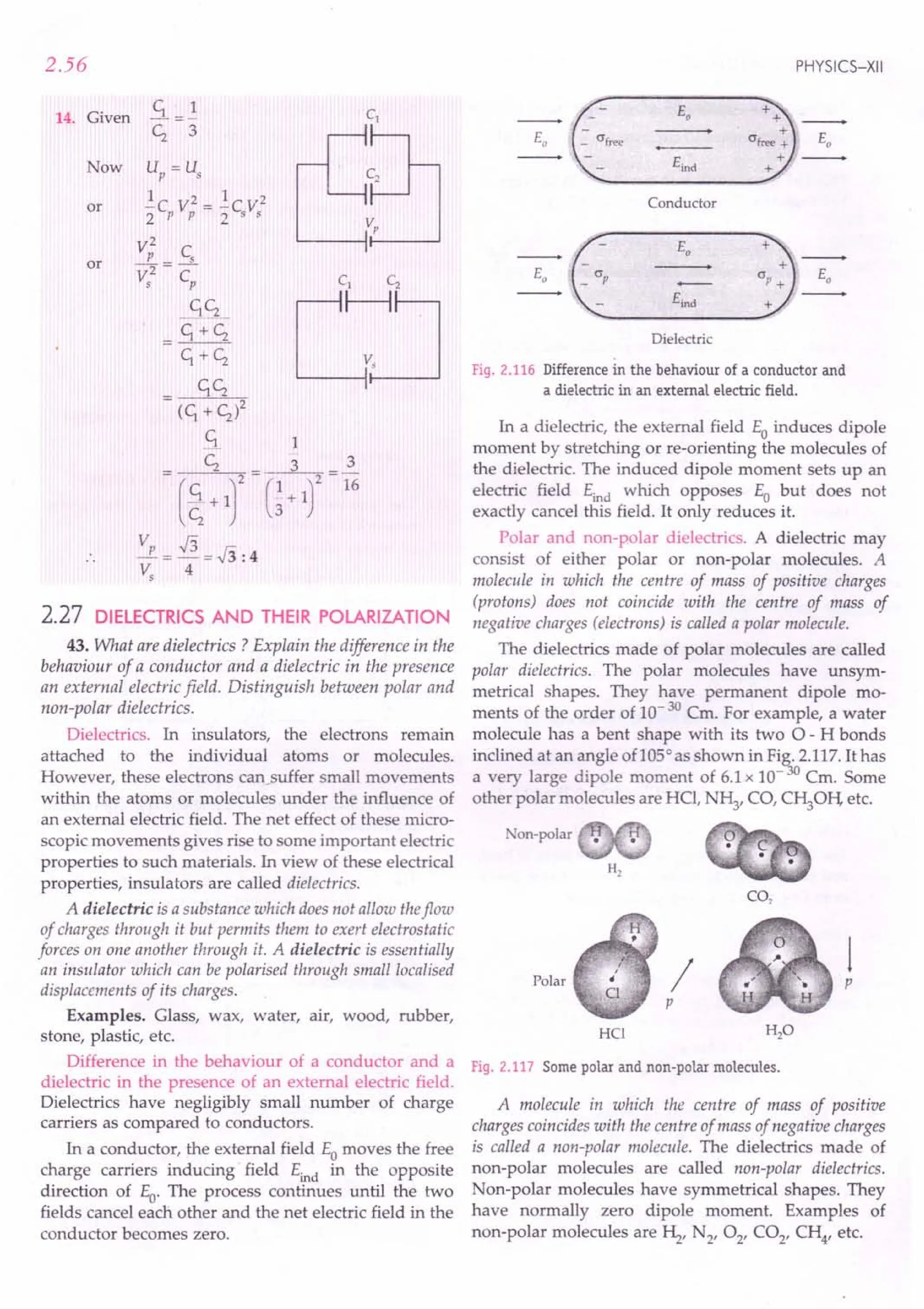
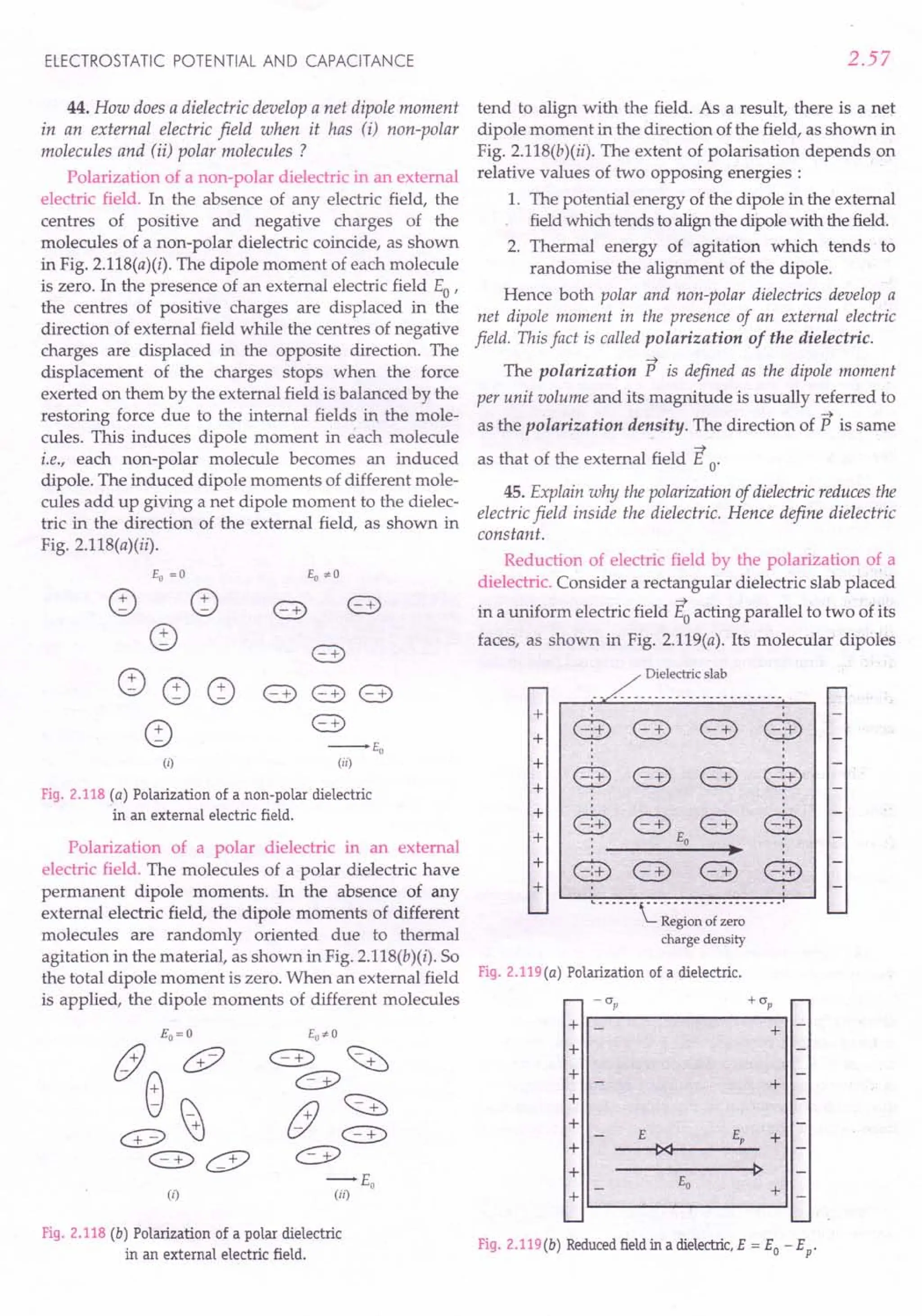
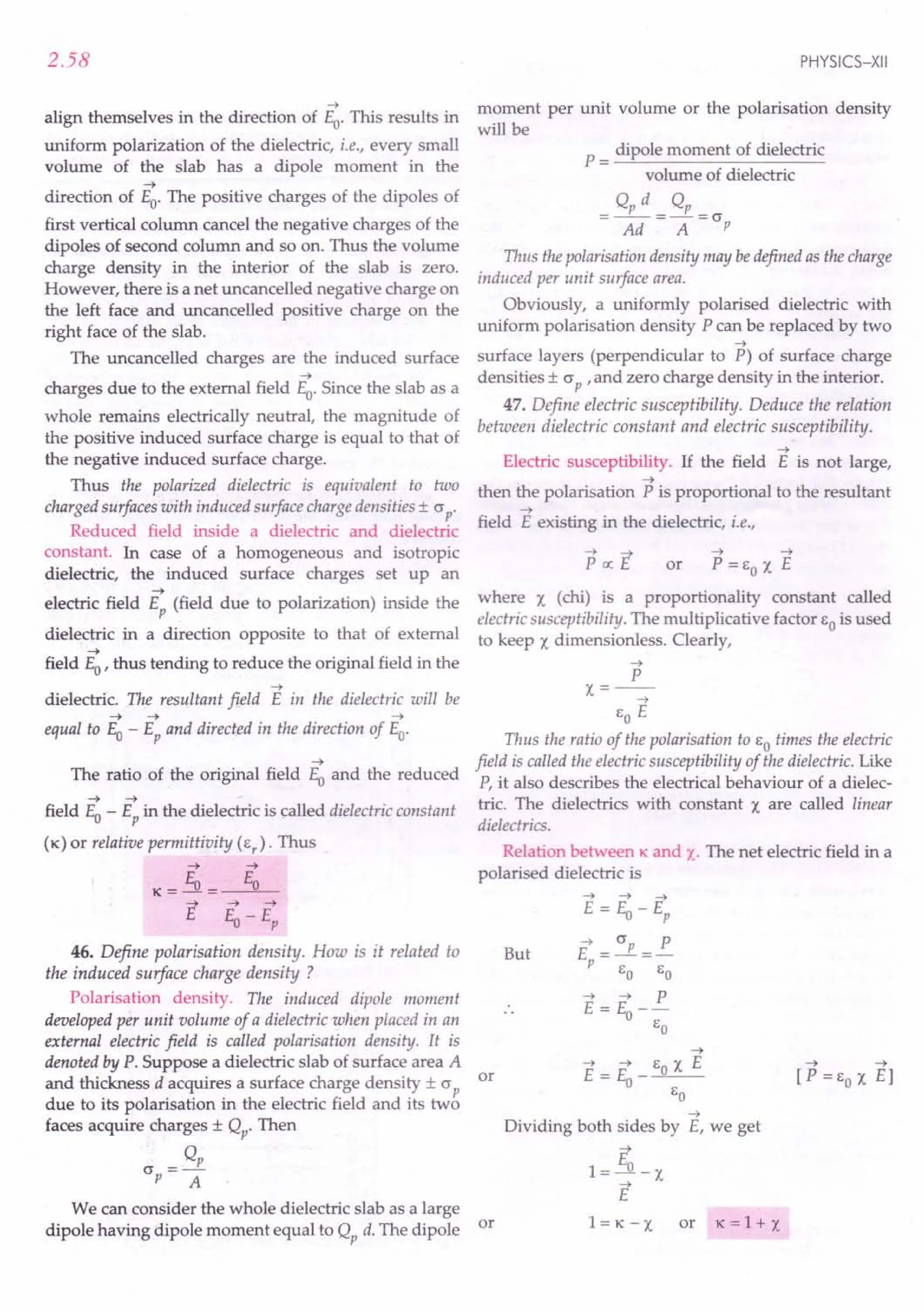
![ELECTROSTATIC POTENTIAL AND CAPACITANCE
2.28 DiElECTRIC STRENGTH
48. What do you mean by dielectric strength of a
dielectric ?
Dielectric strength. When a dielectric is placed in a
very high electric field, the outer electrons may get
detached from their parent atoms. The dielectric then
behaves like a conductor. This phenomenon is called
dielectric breakdown.
The maximum electricfield that can exist in a dielectric
without causing the breakdown of its insulating property is
called dielectric strength of the material.
The unit of dielectric strength is same as that of
electric field i.e., Vm-1. But the more common practical
unit is kV mm-1
.
Table 2.1 Dielectric constants and dielectric
strengths of some common dielectrics.
Dielectric
Dielectric Dielectric strength
constant in kV mm 1
Vacuum 1.00000 00
Air 1.00054 0.8
Water 81 -
Paper 3.5 14
Pyrex glass 4.5 13
Mica 5.4 160
Porcelain 6.5 4
2.29 CAPACITANCE OF A PARALLEl PLATE
CAPACITOR WITH A DIELECTRIC SLAB
49. Deduce the expression for the capacitance of a
parallel plate capacitor when a dielectric slab is inserted
between its plates. Assume the slab thickness less than the
plate separation.
Capacitance of a parallel plate capacitor with a
dielectric slab. The capacitance of a parallel plate
capacitor of plate area A and plate separation d with
vacuum between its plates is given by
_ EoA
CO-
d
Suppose initially the charges on the capacitor plates
are ± Q. Then the uniform electric field set up between
the capacitor plates is
(J Q
Eo=-=--
EO AEo
When a dielectric slab of thickness t < d is placed
between the plates, the field Eopolarises the dielectric.
This induces charge - Qp on the upper surface and
2.59
Fig. 2.120 A dielectric slab placed in a
parallel plate capacitor.
+ Qp on the lower surface of the dielectric. These
induced charges set up a field Ep inside the dielectric in
-+
the opposite direction of Eo. The induced field is given by
E = (J P = R [(J = Q = P, polarisation density]
p EO EO P A
The net field inside the dielectric is
where K is the dielectric constant of the slab. So
between the capacitor plates, the field E exists over a
distance t and field Eo exists over the remaining
distance (d - t). Hence the potential difference
between the capacitor plates is
V = Eo(d - t) + Et = Eo(d - t) + ~o t [.: ~ = K]
= Eo(d - t + .!)= ~ (d - t + .!)
K EOA K
The capacitance of the capacitor on introduction of
dielectric slab becomes
C= Q = EOA
V d-t+.!
K
Special Case If the dielectric fills the entire space
between the plates, then t = d, and we get
E A
C=-O-.K=KC
O
d
Thus the capacitanceof a parallelplate capacitorincreases
K times when its entire spaceisfilled with a dielectricmaterial.
C
Clearly, K = -
Co
Dielectric constant
Capacitance with dielectric between two plates :
Capacitance with vacuum between two plates
Thus the dielectric constant of a dielectric material
may be defined as the ratio of the capacitance of a capacitor
completely filled with that material to the capacitance of the
same capacitor with vacuum between its plates.](https://image.slidesharecdn.com/slaroraclass12thphysicsbyrockytrickster-250318042948-c8b51a5a/75/SL-ARORA-CLASS-12TH-PHYSICS-BY-ROCKY-TRICKSTER-pdf-150-2048.jpg)
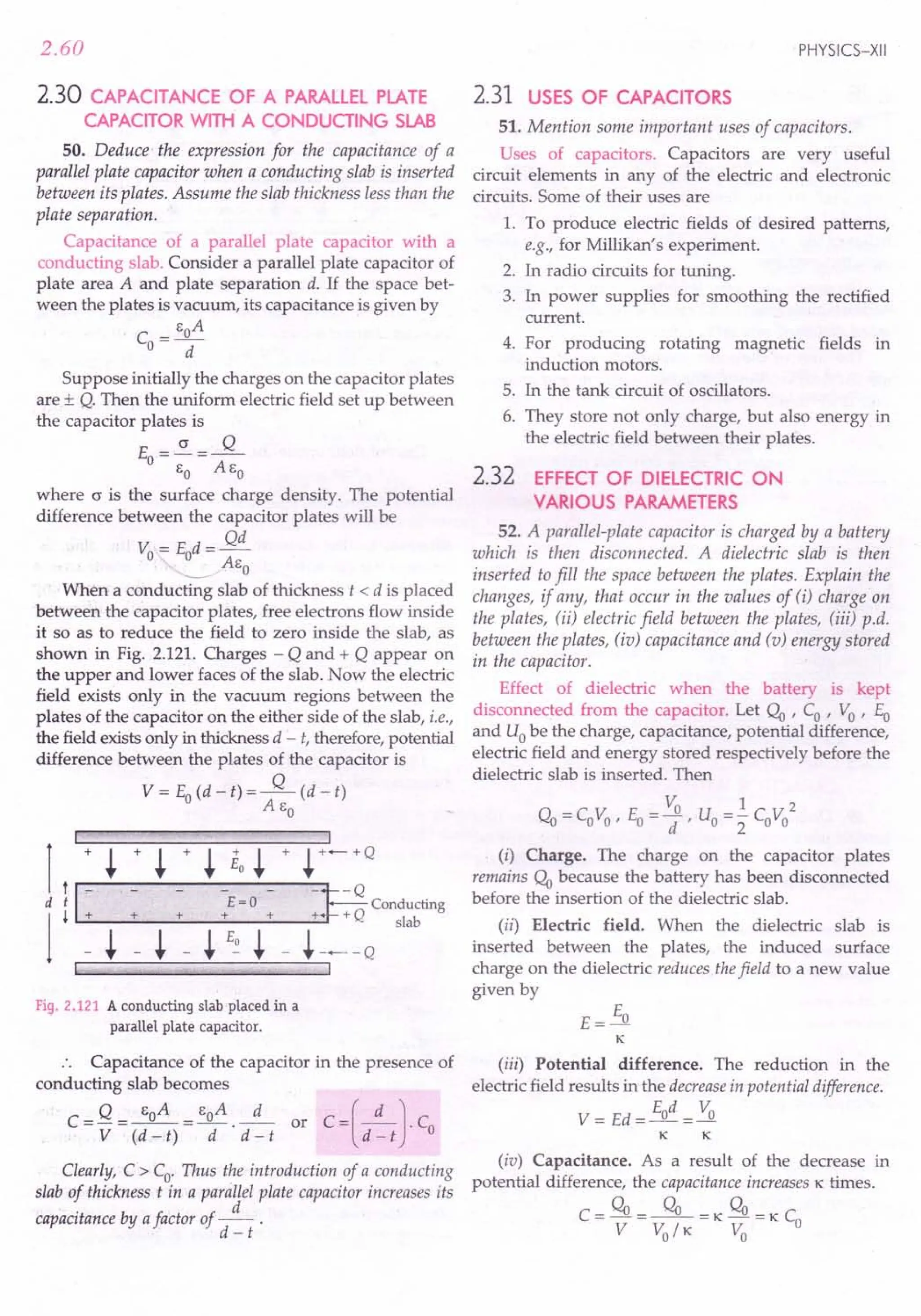

![2.62
Formulae Used
1. Capacitance of a parallel plate capacitor filled with a
dielectric of dielectric constant K.
EoKA
C:=KCo=--
d
2. Capacitance of a parallel plate capacitor with a dielec-
tric slab of thickness t « d) in between its plates,
C= EoA
d -t (1-~)
3. Capacitance of a parallel plate capacitor with a con-
ducting slab of thickness t « d) in between its plates,
C= EO A
d -t
4. Capacitance of spherical capacitor filled with a
dielectric,
ab
C = 41t Eo K. b _ a
5. Capacitance of a cylindrical capacitor filled with a
dielectric,
C = 21t EO K I
b
2303log10 -
a
6. Effect of dielectric with battery disconnected from
the capacitor,
Q = QyrV = Vo , E = Eo, C = KCo' U = Uo
- KKK
7. Effect of dielectric with battery connected across the
capacitor,
Q = K(;b, V = Vo ' E = Eo' C = KCo' U = K Uo
Units Used
Capacitance C is in farad, charge q in coulomb,
potential difference V in volt, area A in m 2,
thicknesses d and t in metre.
Constant Used
Permittivity constant, EO = 8.85 x1O-12C2N-1m -2.
Example 79. In a parallel plate capacitor, the capacitance
increases from 4 ~F to SO~F, on introducing a dielectric
medium between the plates. What is the dielectric constant of
the medium?
Solution.
K = Capacitance with dielectric = SO~F = 20.
Capacitance without dielectric 4 ~F
Example BO. A parallel plate capacitor with air between
the plates has a capacitance of 8 ~F. The separation between
the plates is now reduced by half and the space between them
PHYSICS-XII
isfilled with a medium of dielectric constant 5. Calculate the
value of capacitance of the capacitor in the second case.
[CBSEOD 06]
Solution. Capacitance of the capacitor with air
between its plates,
EA
Co =_0_ =S pF
d
When the capacitor is filled with dielectric (K = 5)
between its plates and the distance between the plates
is reduced by halt capacitance becomes
EOKA EO x 5 x A
C=d/2= d/2 =10Co
or C = 10 x S = 80 pF.
Example B1 . Figure 2.123shows tuio-identical capacitors,
C1 and C2, each of 1 ~F capacitance connected to a battery of
6V. Initially switch '5' is closed. After some time '5' is left
Fig. 2.123
open and dielectric slabs of dielectric constant K = 3 are
inserted tofill completely the space between the plates of the
two capacitors. How will the (i) charge and (ii) potential
difference between the plates of the capacitors be affected
after the slabs are inserted? [CBSE D III
Solution. With switch 5 closed, VI = V2 = 6 V
:. q1 =q2 =1~Fx6V=6~C
When dielectric slabs (K =3) are inserted, capaci-
tance of each capacitor becomes 3 ~F.
P.D. across Cl
, V{ = 6 V
Charge, eft =3 ~Fx 6V = 18~C
With switch 5 open, the p.d. on C2 attains a new
value but charge q2 is still 6 ~C
V' = 6~C =2 V.
2 3 ~F
Example B2. An ebonite plate (K =3), 6 mm thick, is
introduced between the parallel plates of a capacitor of plate
area 2 x 1O-2~ and plate separation 0.01 m Find the
capacitance.
Solution. Here t =6 mm =6x 1O-3m,
A=2x10⁻²
m2
, d =0.01 m, K=3
C = EO A = 8.S5 x 10-12 x 2 x 10-2
d - t ( 1 - ~) 0.01-6 x 10-
3
( 1 - ~)
17.7 x 10:
14
= 29.5 x 10⁻¹² F = 29.5 pF.
6 x 10-](https://image.slidesharecdn.com/slaroraclass12thphysicsbyrockytrickster-250318042948-c8b51a5a/75/SL-ARORA-CLASS-12TH-PHYSICS-BY-ROCKY-TRICKSTER-pdf-153-2048.jpg)
![ELECTROSTATIC POTENTIAL AND CAPACITANCE
x y
Example 83. Two parallel PlateL:J
capacitors, X and Y, have the same
area of plates and same separation
between them. X has air between + -
the plates while Y contains a 12 V
dielectric medium of s, = 4. Fig. 2.124
(i) Calculate capacitance of each capacitor if equivalent
capacitance of the combination is 4 IlF.
(ii) Calculate the potential difference between the plates
of X and Y.
(iii) What is the ratio of electrostatic energy stored in X
and Y ? [CBSE D 04, 09]
Solution. (i) Let Cx = C. Then c, = e,c = 4C
Now X and Yare connected in series.
.. C = CXCy = C. 4C
eq Cx+Cy C+4C
4 IlF = i C or C = 5 IlF
5
Hence Cx =C=5IlF and c, =4C=4x5=20IlF.
(ii) Let V be the p.d. across X. Then p.d. across Y
will be V / 4.
.. V + V = 12 or
4
Hence Vx = V =9.6 V and Vy = V / 4 =2.4 V.
(iii) Energy stored in X = ~ C(9.6 )2 = i= 4 : 1.
Energy stored in Y ~4C(2.4)2 1
/ Example 84. An electric field Eo =3 x 10 4 Vm-1
is
established between the plates, 0.05 m apart, of a parallel
plate capacitor. After removing the charging battery, an
uncharged metal plate of thickness t = 0.01 m is inserted
between the capacitor plates. Find the p.d. across the
capacitor (i) before, (ii) after the introduction of the plate.
(iii) What would be the p.d. if a dielectric slab (K = 2) were
introduced in place of metal plate? [Roorkee 91]
Solution. (i) The p.d. across the capacitor plates
before metal plate is inserted,
Vo = Eo d =3 x 104
x 0.05 = 1500 V.
(ii) As no electric field exists in metal plate, so the
p.d. after the introduction of metal plate is
V = Eo(d - t) =3 x 104
x (0.05 -0.01) = 1200 V.
(iii) When dielectric slab (K =2) is introduced, the
p.d. becomes
V = Eo(d - t)+ Eo t =1200+ 3x 10
4
x 0.01 =1350 V.
. K 2
or
V = 9.6 V
Example 85. A parallel plate capacitor is charged to a
certain potential difference. When a 3.0 mm thick slab is
slipped between the capacitor plates, then to maintain the
2.63
same p.d. between the plates, the plate separation is to be
increased by 2.4 mm Find the dielectric constant of the slab.
Solution. Let Eo be the electric field between the
capacitor plates before the introduction of the slab.
Then, the p.d. between the plates is
Vo=Eod
Suppose the separation between the plates is
increased by d' to maintain the same p.d. after the
introduction of the slab of thickness t. Then
Vo = Eo(d + d' - t) + Eo . t
K
E
Eo (d + d' - t) + -.!1.. t = Eo d
K
K=_t_= 3.0mm =5.
t -d' 3.0 mm -2.4 mm
or
Example 86. The area of parallel plates of an air-filled
capacitor is 0.20 ~ and the distance between them is O.Olm
The p.d. across the plates is 3000 V. When a 0.01 m thick
dielectric sheet is placed between the plates, the p.d. decreases
to 1000 V. Determine (i) capacitance of the capacitor before
placing the sheet (ii) charge on each plate (iii) dielectric
constant of the material tio) capacitance of the capacitor after
placing the dielectric (v) permittivity of the dielectric. Given
Co=8.85 x 10⁻¹² Fm-1
.
Solution. (I) Capacitance of air-filled capacitor is
Co = CoA = 8.85 x 10-
12
x 0.20 = 1.77 x 10⁻¹⁰ F.
d 0.01
(ii) Charge on each plate,
q = CoVo = 1.77 x 10-10 x 3000
= 5.31 x 10⁻⁷ C.
(iii) Dielectric constant of the material is
K- C _ q/V _ Vo _3000_
3
- Co - q / Vo - V -1000 - .
(iv) Capacitance after the dielectric sheet is introduced,
C = K Co =3 x 1.77 x 10-10 = 5.31 x 10⁻¹⁰ F.
(v) Permittivity of the dielectric is
C= K EO = 3 x 8.85 x 10-12 = 2.65 x 10⁻¹¹ Fm -1.
Example 87. The capacitance of a parallel plate capacitor is
50 pF and the distance between the plates is 4 mm It is
charged to 200 V and then the charging battery is removed.
Now a dielectric slab (K = 4) of thickness 2 mm is placed.
Determine (i) final charge on each plate (ii) final potential
difference between the plates (iii) final energy in the
capacitor and (io) energy loss.
Solution. Capacitance of air-filled capacitor,
_ CoA
Co --d- ...
(1)](https://image.slidesharecdn.com/slaroraclass12thphysicsbyrockytrickster-250318042948-c8b51a5a/75/SL-ARORA-CLASS-12TH-PHYSICS-BY-ROCKY-TRICKSTER-pdf-154-2048.jpg)
![2.64
Capacitance with dielectric slab of thickness
t « d) is
C= go A
d-t+t/K
(i) The charge on capacitor plates, when 200 V p.d.
is applied, becomes
q = Co Vo = 50 x 10-12
x 200 = 10-8
C
Even after the battery is removed, the charge of
10- 8 C on the capacitor plates remains the same.
(ii) On placing the dielectric slab, suppose the capa-
citance becomes C and potential difference V. Then
q=Co Vo=CV
V- Co V _d-t+t/K V
-C 0- d 0
or
[Using (1) and (2)]
= 4 - 2 + 2 / 4 x 200 = 125 V.
4
(iii) Final energy in the capacitor is
U = .!qV = .!x 10-8 x 125 = 6.25 x 10- 7 J.
2 2
(iv) Energy loss
1
= uo - u = 2 q(Vo - V)
=.! x 10-8 x (200 -125)
2
= 3.75 x 10⁻⁷
J.
Example 88. A parallel plate capacitor is formed by two
plates, each of area 100 cd, separated by a distance of 1 mm
A dielectric of dielectric constant 5 and dielectric strength
1.9 x 10⁷
Vm-l
is filled between the plates. Find the
maximum charge that can be stored on the capacitor without
causing any dielectric breakdown.
Solution. Electric field between capacitor plates is
given by
E=~=-q-
K go K go A
As the electric field should not exceed 1.9 x 10⁷ Vm -I,
so the maximum charge that can be stored is
q= K go AE
= 5 x 8.85 x 10-12 x 100 x 10-4 x 1.9 x 107
= 8.4 x 10⁻⁶ C.
Example 89. A slab of material of dielectric constant K has
the same area as the plates' of a parallel plate capacitor but
has a thickness 3d / 4, where d is the separation of the plates.
How is the capacitance changed when the slab is inserted
between the plates ? [NCERT]
PHYSICS-XII
...(2)
Solution. If Vo is the potential difference when
there is no dielectric, then the electric field between the
capacitor plates will be
V
E-~
0- d
After the dielectric is inserted, the electric field in
the dielectric reduces to
E
E=~
K
Now the potential difference between the plates
will be
Thus the potential difference decreases by a factor
of (K + 3) /4 K, while the free charge qo on the plates
remains same. The capacitance increases to a new
value given by
C - qo _ 4K qo _ 4K C
-Y--K+3'V
o
-K+3 o·
Example 90
(a) Find the ratio of the capacitances of a capacitor filled
with two dielectrics of same dimensions but of dielectric
constants KI and K2 ' respectively.
(b) A capacitor is filled with two dielectrics of the same
dimensions but of dielectric constants KI = 2 and
K2 =3. Find the ratio of capacities in two possible
arrangements. [MNREC 85]
Solution. (a) The two possible arrangements of the
two dielectrics are shown in Figs. 2.125(a) and (b).
I
-=E2J=-[J
I
K2
Fig. 2.125 (a) (b)
(i) The arrangement (a) can be supposed to be a
parallel combination of two capacitors, each with plate
area A/2 and separation d. Therefore, the total capa-
citance is](https://image.slidesharecdn.com/slaroraclass12thphysicsbyrockytrickster-250318042948-c8b51a5a/75/SL-ARORA-CLASS-12TH-PHYSICS-BY-ROCKY-TRICKSTER-pdf-155-2048.jpg)
![ELECTROSTATIC POTENTIAL AND CAPACITANCE
(ii) The arrangement (b) can be supposed to be a
series combination of two capacitors, each with plate
total
area A and separation d/2. Therefore, the
capacitance C ' is given by
1 1 1 1 1
- = - + - = --,-- + ---;--
c C' C 6 AK 60 AK2
1 2 _0
__ 1
d/2 d/2
d (1 1)
= 26
0
A -;s + K2
C' = 260 A ( KlK2 )
d Kl + K2
or
Ratio of the capacitances in the two arrangements is
2
C _ 60 A(K1 + K2) d(K1 + K2) _ (K1 + K2)
C,- 2d '26
0
AK1
K2- 4K1K2
(b) Here Kl =2, K2=3
C (2 + 3)2 25
C 4x 2 x 3 24
~roblems For Practice
1. A parallel-plate capacitor having plate area 100cm2
and separation 1.0 mm holds a charge of 0.12~C
when connected to a 120 V battery. Find the
dielectric constant of the material filling the gap.
(Ans.11.3)
~. Find the length of the paper used in a capacitor of
capacitance 2 ~F, if the dielectric constant of the
paper is 2.5 and its width and thickness are 50 mm
and 0.05 mm, respectively. (Ans. 90 m)
3. A parallel-plate capacitor consists of 26 metal strips,
each of 3 em x 4 em, separated by mica sheets of
dielectric constant 6 and uniform thickness 0.2 mm.
Find the capacitance. (Ans. 7.97x 10- 9 F)
4. A parallel-plate capacitor of capacity 0.5~F is to be
constructed using paper sheets of thickness 0.04mm
as dielectric. Find how many circular metal foils
of diameter 0.1 m will have to be used. Take the
dielectric constant of paper used as 4. (Ans. 73)
5. When a slab of insulating material 4 mm thick is
introduced between the plates of a parallel plate
capacitor, it is found that the distance between the
plates has to be increased by 3.2 mm to restore the
capacitance to the original value. Calculate the
dielectric constant of the material. (Ans. 5)
6. The two plates of a parallel plate capacitor are
.4 mm apart. A slab of dielectric constant 3 and
thickness 3 mm is introduced between the plates
with its faces parallel to them. The distance
between the plates is so adjusted that the capa-
2.65
citance of the capacitor becomes 2/3rd of its original
value. What is the new distance between the
plates? [CBSE OD OSC] (Ans. 8 mm)
7. The distance between the parallel plates of a charged
capacitor is 5 cm and the intensity of electric field is
300 V em-1. A slab of dielectric constant 5 and thick-
ness 1 em is inserted parallel to the plates. Determine
the potential differencebetween the plates,before and
after the slab is inserted ? (Ans. 1500V, 1260V)
8. A parallel plate capacitor with plate separation
5 mm is charged by a battery. It is found that on
introducing a mica sheet 2 mm thick, while keeping
the battery connections intact, the capacitor draws
25%more energy from the battery than before. Find
the dielectric constant of mica. (Ans. 2)
9. Figure 2.126 shows a parallel plate capacitor of
plate area A and plate separation d. Its entire space
is filled with three different dielectric slabs of same
thickness. Find the equivalent capacitance of the
arrangement. [Ans. C = 3 eo A Kl K2K3 ]
d (K1K2+ K2K3+ K3K1)
r
iT P
d/3
+
d/3 Kj K2 K3
+
d/3
.i.
bB
Fig.2.127
r- I_A__ ---"l
Fig.2.126
10. The space between the plates of a parallel plate
capacitor of capacitance C is filled with three
dielectric slabs of equal thickness, as shown in
Fig. 2.127. If the dielectric constants of the three
slabs are K1
,K2and K3
, find the new capacitance.
[Ans. C=~(KI + K2+ K3)]
3
11. A slab of material of dielectric constant Khas the
same area as the plates of a parallel plate capacitor
but has thickness d /2, where d is the separation
between the plates. Find the expression for the
capacitance when the slab is inserted between the
plates. [CBSE F 10; OD 13] (Ans. ~C )
K+l 0
HINTS
1. Capacitance,
If K is the dielectric constant, then
C= K eo A = Kx8.85 x10-
12
xlOOx10-
4
= 1O-9F
d 1.0 x 10⁻³
:. K =11.3.](https://image.slidesharecdn.com/slaroraclass12thphysicsbyrockytrickster-250318042948-c8b51a5a/75/SL-ARORA-CLASS-12TH-PHYSICS-BY-ROCKY-TRICKSTER-pdf-156-2048.jpg)
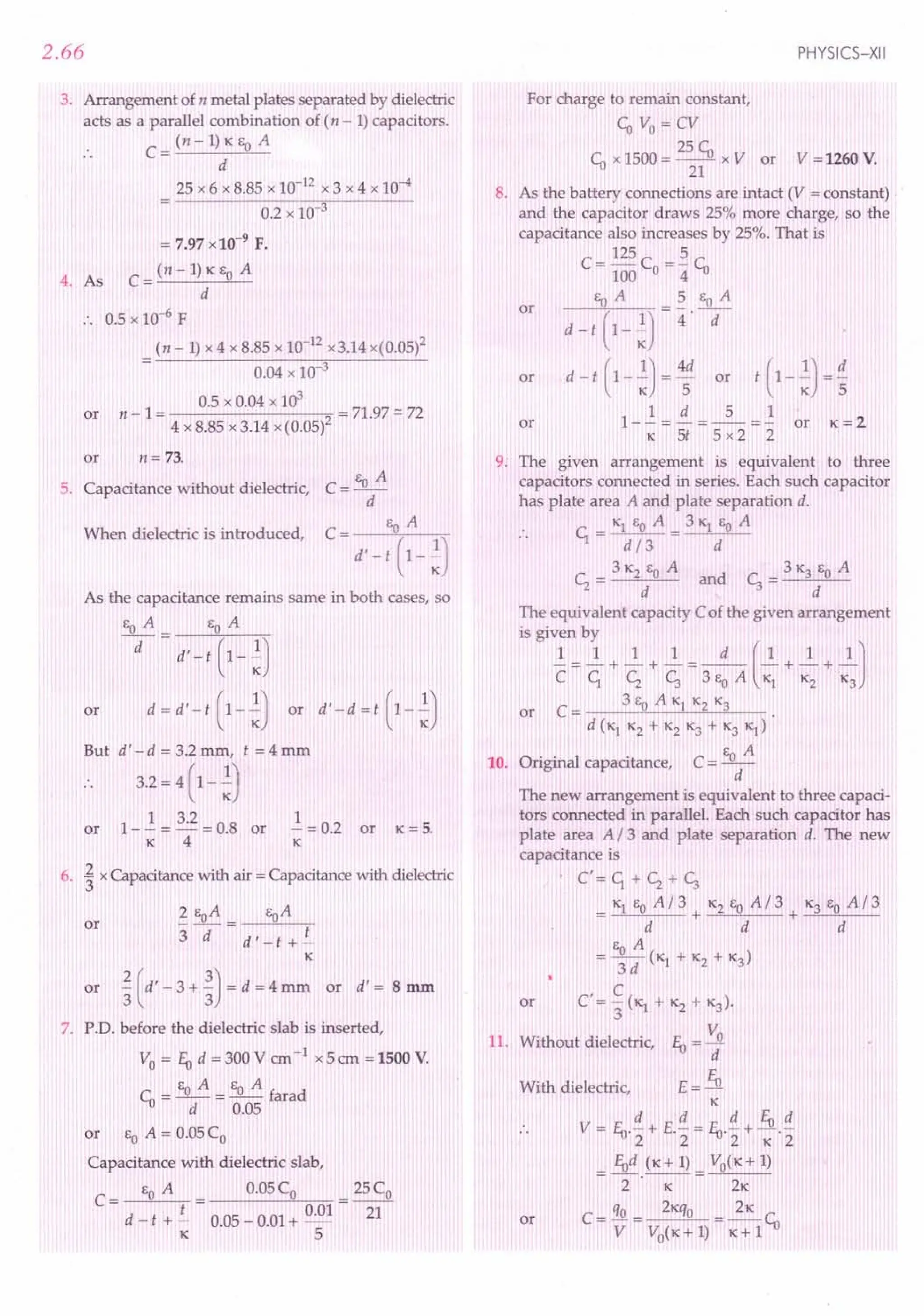
![ELECTROSTATIC POTENTIAL AND CAPACITANCE
2.33 DISCHARGING ACTION OF SHARP
POINTS : CORONA DISCHARGE
54. Briefly explain discharging action of sharp points
or corona discharge.
Discharging action of sharp points : Corona
discharge. When a spherical conductor of radius r
carries a charge q, its surface charge density is
G=!L .:s:
A . 4n r
2
Electric field on the surface is
LowE +
Fig. 2.128 Corona discharge.
The pointed end of a conductor is highly curved
and its radius of curvature r very small. If the con-
ductor is given a charge q, then the charge density Gat
the pointed end will be very high. Consequently, the
electric field near the pointed end will be very high
which may cause the ionisation or electrical break-
down of the surrounding air. The oppositely charged
ions neutralise the pointed end while the similarly
charged ions are repelled away. Fresh air molecules
come near the pointed end and take away its charge,
setting up a kind of electric wind. This process by which
the charge at the pointed end of a conductor gets discharged
is called corona discharge. The discharge is often
accompanied by a visible glow near the pointed end.
2.34 COLLECTING ACTION OF A
HOLLOW CONDUCTOR
55. A small sphere of radius r and charge q is enclosed
by a spherical shell of radius R and charge Q. Show that if
q is positive, charge q will necessarily flow from the
sphere to the shell (when the two are connected by a wire)
no matter what the charge Q on the shell is. [NCERT]
Collecting action of a hollow sphere. Consider a
small sphere of radius r placed inside a large spherical
shell of radius R. Let the spheres carry charges q and Q,
respectively.
2.67
Total potential on the outer sphere,
VR
= Potential due to its own charge Q
+ Potential due to the charge q on
the inner sphere
= 4nJ~+ ~]
Potential on the inner
sphere due to its own charge is
1 q
V =---
1 4n eo . r
As the potential at every
point inside a charged sphere
is the same as that on its
surface, so potential on the
inner sphere due to charge Q
on outer sphere is
V =_1_ Q
2 4ne
o· R
Total potential on inner sphere
Vr = 4:eJ;+ ~]
Insulating
suspension
Fig. 2.129 Small charged
sphere suspended inside a
charged spherical shell.
Hence the potential difference is
V - V = -q- [!-!]
r R 4ne
o
r R
So if q is positive, the potential of the inner sphere
will always be higher than that of the outer sphere.
Now if the two spheres are connected by a conducting
wire, the charge qwill flow entirely to the outer sphere,
irrespective of the charge Q already present on the
outer sphere. In fact this is true for conductors of any
shape.
2.35 *
VAN DE GRAAFF GENERATOR
56. Explain the basic principle, construction and
working of Van de Graaff generator.
Van de Graaff generator. It is an electrostatic
generator capableof building up high potential differences of
the order of107
volts.
Principle. The working of a Van de Graaff gene-
rator is based on following two electrostatic phenomena:
(i) Discharging action of sharp points (corona
discharge) i.e., electric discharge takes place in air or
gases readily at the pointed ends of conductors.
(ii) If a charged conductor is brought into internal
contact with a hollow conductor, all of its charge
transfers to the hollow conductor, howsoever high the
potential of the latter may be.](https://image.slidesharecdn.com/slaroraclass12thphysicsbyrockytrickster-250318042948-c8b51a5a/75/SL-ARORA-CLASS-12TH-PHYSICS-BY-ROCKY-TRICKSTER-pdf-158-2048.jpg)
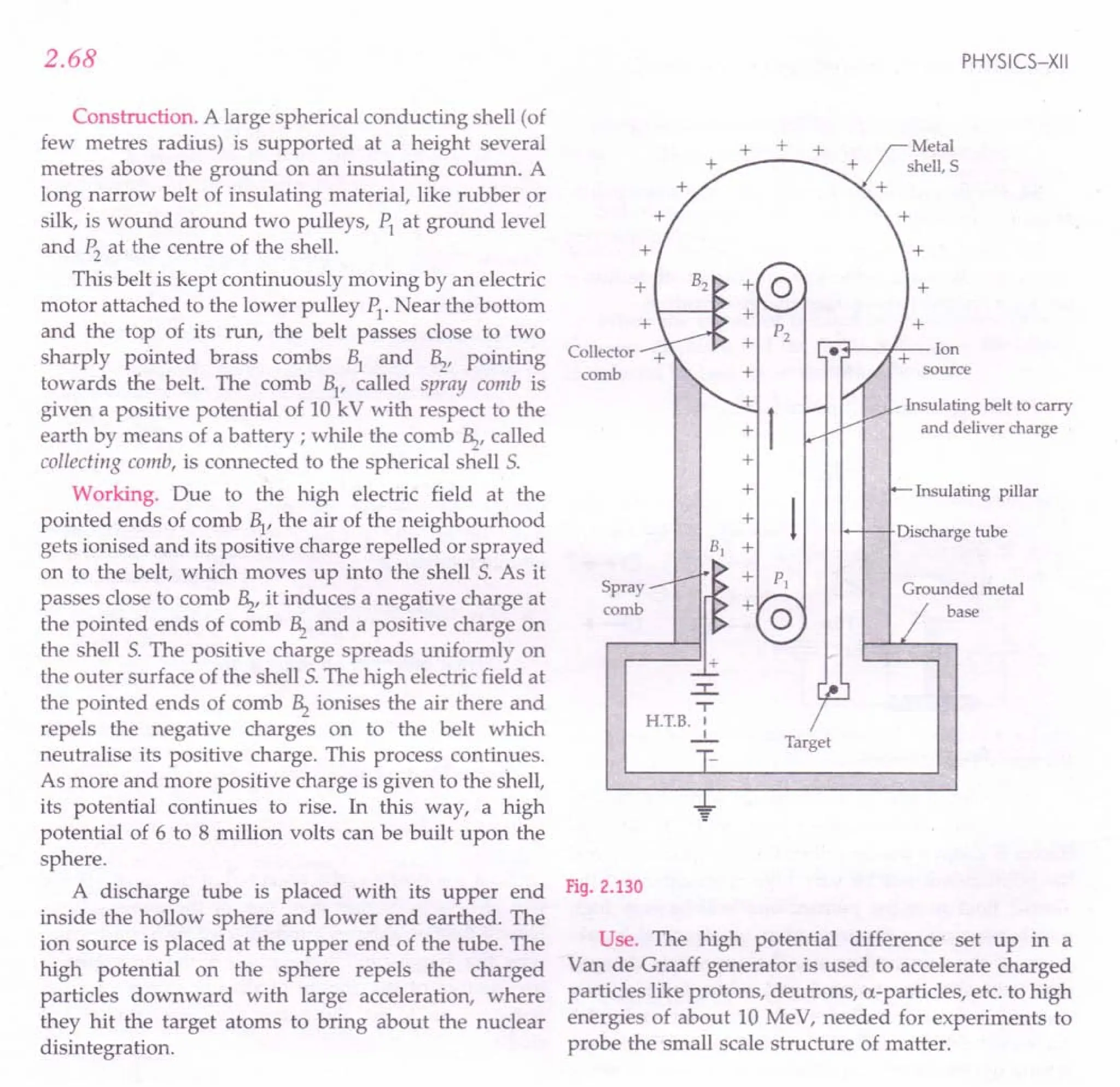
![G I DELI N ES To NCERT EXERCISES
2.1. Two charges 5 x 1O-8C and -3 x 10⁻⁸ C are located
16 cm apart. At what point on the line joining the two charges is
the electric potential zero ? Take the potential at infinity to be
zero.
Ans. Zero of electric potential for two charges. As
shown in Fig. 2.186, suppose the two charges are placed on
X-axis with the positive charge located at the origin 0.
-8 -8
ql = 5x 10 C q2 = - 3 x 10 C
·.-----------+I--------------~·
o p A
I--- x ----0·01+1_ --- 0.16
- x -----I
Fig. 2.186
Let the potential be zero at the point P and OP = x. For
x < 0 (i.e., to the left of 0), the potentials of the two charges
or
cannot add up to zero. Clearly, x must be positive. If x lies
between 0 and A, then
Vl
+ V2 = 0
_1_ [ ql + q2 ] - 0
4TCE
O
x 0.16-x
9 [ 5 x 10- 8 3 x 10- 8 ]
or 9 x 10 - = 0
x 0.16 - x
5 3 = 0
x 0.16 - x
or
or x = 0.10 m =10 em,
The other possibility is that x may also lie on OA
produced, as shown in Fig. 2.187.
-8 -8
ql=5xl0 C q2=-3xlO C
• • I
o A P
11+-: 0_.1_6_-_-_-~-x--'I'-- x - 0.16=1
Fig. 2.187
As V;+ V2 =0
_1_[ 5 x10-
8
_ 3x10-
8
] =0
4TC EO X X - 0.16
5 3 =0
x x - 0.16
or x = 0.40 m = 40 em.
Thus the electric potential is zero at 10 em and 40 em
away from the positive charge on the side of the negative
charge.
2.2. A regular hexagon of side 10em has a charge of 5 J.1C at
each of its vertices. Calculate the potential at the centre of the
hexagon.
Ans. Clearly, distance of each charge from the centre
o is
r= IDem =D.1Dm](https://image.slidesharecdn.com/slaroraclass12thphysicsbyrockytrickster-250318042948-c8b51a5a/75/SL-ARORA-CLASS-12TH-PHYSICS-BY-ROCKY-TRICKSTER-pdf-160-2048.jpg)
![2.92
Fig. 2.188
Magnitude of each charge is
q = 5 IlC = 5 x io+c
:. Potential at the centre 0 is
1 q 6 x 9 x 109
x 5 x 10-6
V=6.--.-=-------
41tEO r 0.10
= 2.7 x10⁶
V.
2.3. Two charges + 2 IlC and - 2 IlC are placed at points A
and B, 6 em apart. (i) Identify an equipotential surface of the
system (ii) What is the direction of the electric field at every or
point on the surface ?
Ans. (i) The equipotential surface will be a plane
normal to AB and passing through its midpoint 0, as
shown in Fig. 2.189. It has zero potential everywhere.
A o
Equipotential
surface
Fig. 2.189
(ii) The direction of electric field is normal to the plane
in the direction AB i.e., from positive to negative charge.
2.4. A spherical conductor of radius 12 cm has a charge of
1.6 x 10⁻⁷
C distributed uniformly on its surface. What is the
electric field
(a) inside the sphere (b) just outside the sphere
(c) at a point 18 cm from the centre of the sphere?
Ans. Refer to the solution of Example 75 on page 1.60.
2.5. A parallel plate capacitor with air between the plates
has a capacitance of 8 pF (lpF = 10-12
F). What will be the
capacitance if the distance between the plates be reduced by half,
the space between them is filled with a substance of dielectric
constant, lC = 6 ?
Ans. Capacitance of the capacitor with air between its
plates,
E A
= -0-=8pF
d
PHYSICS-XII
When the capacitor is filled with dielectric (lC = 6)
between its plates and the distance between the plates is
reduced by half, capacitance becomes,
EO lC A EO x 6 x A EoA
C'=--= =12-
d' d / 2 d
C' = 12 x 8 = 96 pF.
2.6. Three capacitors each of capacitance 9 pF are connected
in series. (a) What is the total capacitance of the combination?
(b) What is the potential difference across each capacitor when
the combination is connected to a 120 V supply ?
Ans. (a) If C is the equivalent capacitance of the series
combination, then
111111131
-=-+-+-=-+-+-=-=-
CC1, <; c;99993
or
C= 3 pF.
(b) As all the capacitors have equal capacitance, so
potential drop t1 V would be same across each capacitor.
. . V = t1 VI + t1 V2
+ t1 V3
= t1 V + t1 V + t1 V = 3t1 V
t1 V = V = 120 = 40 V.
3 3
or
2.7. Three capacitors of capacitances 2 pF, 3 pF and 4 pF are
connected in parallel. (a) What is the total capacitance of the
combination? (b) Determine the charge on each capacitor if the
combination is connected to a 100 V supply.
Ans. (a) For the parallel combination, total capacitance
is given by
C = C1, + <; + <; = 2 + 3 + 4 = 9 pF.
(b) When the combination is connected to 100 V
supply, charges on the capacitors will be
ql = C1,V =2x10-12
x100=2x10⁻¹⁰C
q2 = <;V = 3 x 10-12
x 100 = 3 x1().-lO
C
q2 = c;V =4x10-12
x100=4x10⁻¹⁰C.
2.8. In a parallel plate capacitor with air between the plates,
each plate has an area of 6 x 10⁻³
m2
and the distance between
the plates is 3 mm. Calculate the capacitance of the capacitor. If
the capacitor is connected to a 100 V supply, what is the charge
on each plate of the capacitor ?
Ans. Capacitance of capacitor with air between its
plates is
Co = EoA = 8.85 x10-12
x6 x 10-3
d 3x10-3
= 1.8x 10⁻¹¹
F = 18 pF.
Charge,
q = CoV = 1.8 x10-11
x 100 = 1.8 x10⁻⁹
C.
2.9. Explain what would happen if in the capacitor given in
Exercise 2.8, a 3 mm thick mica sheet (of dielectric constant = 6)
were inserted between the plates, (i) while the voltage supply
remains connected (ii) after the supply was disconnected.
[CBSE Sample Paper 98]](https://image.slidesharecdn.com/slaroraclass12thphysicsbyrockytrickster-250318042948-c8b51a5a/75/SL-ARORA-CLASS-12TH-PHYSICS-BY-ROCKY-TRICKSTER-pdf-161-2048.jpg)
![ELECTROSTATIC POTENTIAL AND CAPACITANCE
Ans. From the above question, we have
CD= 1.8 x 10⁻¹¹ F = 18 pF, qo= 1.8 x 10⁻⁹
C
Also, K = 6
(i) When the voltage supply remains connected, the
potential difference between capacitor plates remains
same i.e., 100 V.
The capacitance increases K times.
.. C = K CD= 6 x 18 = 108 pF.
The charge on the capacitor plates will be
q = CV = 108 x 10-12 x 100 = 1.08 x10⁻⁸
C.
(ii) After the supply is disconnected, the charge on the
capacitor plates remains same i.e.,
qo= 18 x 10- 9 C
The capacitance increases K times.
C= K CD=108 pF.
The potential difference between the capacitor plates
becomes
v = Va = 100 =16.6 V.
K 6
2.10. A 12 pF capacitor is connected to a 50 V battery. How
much electrostatic energy is stored in the capacitor?
Ans. Here C = 12 pF = 12 x 10-12 F, V = 50 V
Energy stored,
U = -.!CV2 = -.!x12x10-12 x(50)2 =1.5 x10⁻⁸ J.
2 2
2.11. A 600 pF capacitor is charged by a 200 V supply. It is
then disconnected from the supply and is connected to another
uncharged 600 pF capacitor. How much electrostatic energy is
lost in the process ?
Ans. Here C; = 600 pF, VI = 200 V,
<; = 600 pF, V2 = 0
Common potential,
V = C;VI + <;V2 = 600 x 10-
12
x200+ 0 = 100 V
C;+ <; (600+ 600) x10-12
Initial energy stored,
1 2 1 -12 2
Ui = U1="2C;VI ="2 x600x10 x(200)
= 12x10-6
J
Final energy stored,
1 2
Uf ="2(C; + <;)V
= -.!(600+ 600) x 10-12x(100)2 = 6 x 10- 6 J
2
Electrostatic energy lost,
6.U = U, - U
f
= 12x10--{;-6 x10-6
= 6 x10⁻⁶
J
2.93
2.12. A charge of 8 mC is located at the origin. Calculate
the work done in taking a small charge of - 2 x 10⁻⁹
Cfrom
a point P (0, 0, 3 em) to a point Q (0, 4 em, 0) via a point R (0,
6 em, 9 em).
Ans. As the work done in taking a charge from one
point to another is independent of the path followed,
therefore
W = qo[VQ - VpJ = qo[-q- - -q-]
41t EO r2 41t Eo '1
= 4~:J~-I]
z R(O, 6 ern, 9 ern)
P(O, 0, 3 em)
q = 2 me Q(O, 4 ern, 0)
x
Fig. 2.190
Here q= 8 mC = 8 x 1O-3
C, qo= - 2 x 10⁻⁹
C
'1 = 3 em = 3 x 10⁻² m, r2
= 4 em = 4 x10⁻²m
.. W = - 2 x 10-9
x8 x 10-3
x9 x109
x[ 4 x ~o-2 - 3x :0- 2 ]
= 1.2 J.
2.13. A cube of side b has a charge q at each of its vertices.
Determine the potential and electric field due to this charge
array at the centre of the cube.
Ans. Length of longest diagonal of the cube
= ~b2 + b2 + b2 = J3 b
Distance of each charge (placed at vertex) from the
centre of the cube is
r= J3 b
2
:. Potential at the centre of the cube is
V = 8._l_.!i=8x_1_.~
41t Eo r 41t EO J3b
4q](https://image.slidesharecdn.com/slaroraclass12thphysicsbyrockytrickster-250318042948-c8b51a5a/75/SL-ARORA-CLASS-12TH-PHYSICS-BY-ROCKY-TRICKSTER-pdf-162-2048.jpg)
![2.94
Electric fields at the centre due to any pair of charges
at the opposite comers will be equal and opposite thus
cancelling out in pairs. Hence resultant electric field at the
centre will be zero.
2.14. Two tiny spheres carrying charges 1.5JlC and 2.5JlC
are located 30 em apart. Find the potential (a) at the midpoint of
the line joining the two charges, and (b) at a point 10 emfrom
this midpoint in a plane normal to the line and passing through
the midpoint.
Ans. The two situations are shown in Fig. 2.191.
C
§f:;&;
6~¥
~~/
A~------...J...------->eB
15 em 0 15em
q] = 1.5 JlC q2 = 2.5 JlC
~
IDem ~
Fig. 2.191
(a) Here 1. = r2
= 15em = 0.15 m
:. Potential at the midpoint 0 of the line joining the
two charges is
v: - _1_ [ql + q2]
o - 4m;0 1. r2
= 9 x 10⁹[ 1.5 x 10-
6
+ 2.5 x 10⁻⁶] V
0.15 0.15
= 9 x 109 x 10-6 [ 10 + 5;] V
= 9 x 103 x 80 V = 2.4 xl0s V.
3
(b) Here 1. = r2
= ~102 + 152
= 55:::.18
em = 0.18 m
.. Potential at point C due to the two charges is
v: - _1_ [ql + q2]
c - 41tEo 1. r2
9 [ 1.5 x 10⁻⁶ 2.5 x 10⁻⁶]
= 9xl0 + ----
0.18 0.18
9 x 109 x 4 x 10-6 5
------=2xl0 V.
0.18
2.15. A spherical conducting shell of inner radius 1. and
outer radius r2
has a charge Q.
(a) A charge q is placed at the centre of the shell. What is the
surface charge density on the inner and outer surfaces of
the shell ?
(b) Is the electric field inside a cavity (with no charge) zero
even if the shell is not spherical, but has any irregular
shape ? Explain.
PHYSICS-XII
Ans. (a) The charge q placed at the centre of the shell
induces a charge - q on the inner surface of the shell and
charge + q on its outer surface.
.. Surface charge density on the inner surface of the
shell
charge q
---2
surface area 41t1.
Surface charge density on the outer surface of the shell
Q+q
4m:2 .
2
(b) Even if the shell is not spherical, the entire charge
resides on its outer surface. The net charge on the inner
surface enclosing the cavity is zero. From Gauss's theorem,
electric field vanishes at all points inside the cavity. For a
cavity of arbitrary shape, this is not enough to claim that
electric field inside must be zero. The cavity surface may
have positive and negative charges with total charge zero.
S
P@_R
+ -
Q
Fig. 2.192 Electric field vanishes inside a cavity of any shape.
To overrule this possibility, consider a closed loop
PQRSP, such that part PQR is inside the cavity along a
line of force and the part RSP is inside the conductor.
Since the field inside a conductor is zero, this gives a
network done by the field (in part RSP) in carrying a test
charge over a closed loop. But this is not possible for a
conservative field like the electrostatic field. Hence there
are no lines of force (i.e., no field), and no charge on the
inner surface of the conductor, whatever be its shape.
2.16. (a) Show that the normal component of electrostatic
field has a discontinuity from one side of a charged surface to
another given by
4 ~ " cr
(f2-f1).n =-
Eo
where n is a unit vector normal to the surface at a point and cris
the surface charge density at that point. (The direction of n is
from side 1 to side 2)
Hence show that just outside a conductor, the electric field
is cr~ / EO'
(b) Show that the tangential component of electrostatic field
is continuous from one side of a charged surface to another.
[Hint: For (a), Use Gauss's law. For (b), use the fact
that work done by electrostatic field on a closed loop is
zero.]](https://image.slidesharecdn.com/slaroraclass12thphysicsbyrockytrickster-250318042948-c8b51a5a/75/SL-ARORA-CLASS-12TH-PHYSICS-BY-ROCKY-TRICKSTER-pdf-163-2048.jpg)
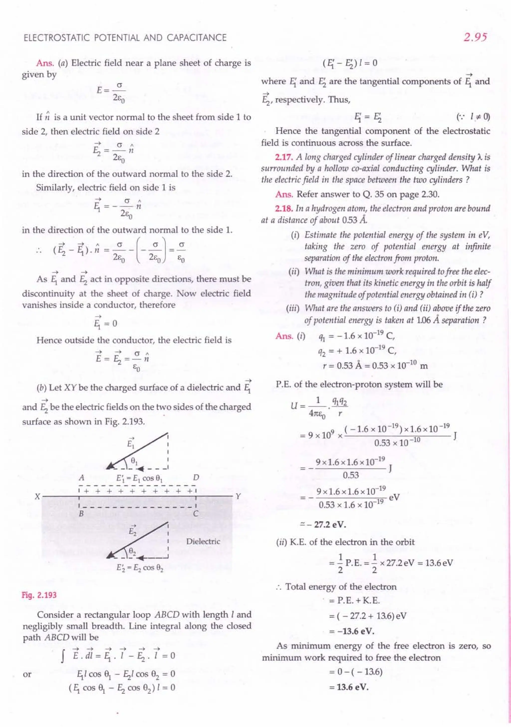
![2.96
(iii) When the zero of potential energy is not taken at
infinity, the potential energy of the system is
U - ql q2 []. _ ~]
4m,0 1. r2
= 9 x 10⁹ x(-1.6 x 10⁻¹⁹
) x 1.6 x 10⁻¹⁹
[ 1 1] J
x 0.53 x 10-10 - 1.06 x 10⁻¹⁰
9 x 109
x 1.6 x 10-19
x 1.6 x 10-19
[ 1]
- - 1-- eV
- . 1.6 x 10-19 x 0.53 x 10-10 2
9 x 1.6
= ----eV =-13.6eV
0.53 x 2
This indicates that the K.E. of 13.6 eV of case (i) is used
up in increasing the P.E. from -27.2eV to -13.6eV as the
electron is carried from 0.53 A to 1.06 A position. K.E. in
this situation should be zero. As the total energy in this
case is zero, therefore, minimum work required to free the
electron
= 0 - (-13.6eV) = 13.6 eV.
2.19. If one of the two electrons of a H2 molecule is removed,
we get a hydrogen molecular ion (H2
+). In the ground state of a
H; ion, the two protons are separated by roughly 15 Ii, and the
electron is roughly 1A from each proton. Determine the
potential energy of the system. Specify your choice of the zero of
potential energy.
Ans. The system of charges is shown in Fig. 2.194.
qz = + qfl--------:---- ...•
q3 = + q
Proton rz = 1.5A Proton
Fig. 2.194
Charge on an electron,
% = - e = - 1.6 x 10⁻¹⁹
C
Charge on each proton,
q2 = q3 = + e = + 1.6 x 10⁻¹⁹
C
If the zero of potential energy is taken at infinity, then
potential energy of the system is
U = U + U + U = _1_ [ ql q2 + q2q3 + ql q3 ]
12 23 13 41ts r. t: t:
o 1 2 3
_ 1 [ (-q)q + q.q + (-q)q ]
- 41tso 1 x 10 10 1.5 x 10 10 1 x 10 10
_ e
2
[-1+2.-1] [q=e]
- 41ts
o
x10 10 1.5
PHYSICS-XII
(1.6 x 10⁻¹⁹
)2 x 9 x 109
x (- 4)
10-10 3 J
(1.6 x 10⁻¹⁹
)2 x 9 x 109 x 4
=- 19 eV=-19.2eV
1.6 x 10- x 3
[.: 1eV = 1.6 x 10⁻¹⁹
JJ
2.20. Two charged conducting spheres of radii a and bare
connected to each other by a wire. What is the ratio of electric
fields at the surfaces of the two spheres? Use the result obtained
to explain why charge density on the sharp and pointed ends of a
conductor is higher than that on its flatter portions.
Ans. The charges will flow between the two spheres
till their potentials become equal. Then the charges on the
two spheres would be
Q1 = c;V =.S.
Q2
CzV Cz
.S. = ~
Cz b
But
The ratio of the electric fields at the surface of the two
spheres will be
Also,
1 Q1
11 ~ . 7 q b2
a b2
b
Ez = _1_ Q2
= Q
2
. a2 = b' a2 = -;;.
41tSo . b2
!i.= 0'1
Ez 0'2
~=~
0'2 a
Thus the surface charge densities are inversely
proportional to the radii of the spheres. Since the flat
portion may be considered as a spherical surface of large
radius and a pointed portion as that of small radius, that is
why, the surface charge density on the sharp and pointed
ends of a conductor is much higher than that on its flatter
portion.
2.21. Two charges -q and + q are located at points (O,O,-a)
and (O,O,a) respectively.
(i) What is the electrostatic potential at the points
(O,O,z) and (x,y,O) ?
(ii) Obtain the dependence of potential on the distance r
of a point from the origin when r / a » 1
(iii) How much work is done in moving a small test
charge from the point (5, 0, 0) to (-7,0,0) along the
x-axis?
Does the answer change if the path of the test charge
between the same points is not along the x-axis ?](https://image.slidesharecdn.com/slaroraclass12thphysicsbyrockytrickster-250318042948-c8b51a5a/75/SL-ARORA-CLASS-12TH-PHYSICS-BY-ROCKY-TRICKSTER-pdf-165-2048.jpg)
![ELECTROSTATIC POTENTIAL AND CAPACITANCE
Ans. (i) When the point P lies closer to the charge + q
as shown in Fig. 2.195(a), the potential at this point P
will be
V = 4n
1
eJ ~ -!]= 4n
1
eJ z ~ a - z - ~- a) ]
q 2a
= 4ne 'T7
o -
V=_l p_
4n eo . z2 - a2 .
or [.: p = q x 2a]
z
P (0, 0, z)
+ q (0, 0, a)
y (a)
a
-q (0, 0, -a)
X
Z
+q (0, 0, a)
y
(b)
a
- q (0, 0, - a)
X P (0, 0, z)
Fig. 2.195
When the point P lies closer to charge - q, as shown in
Fig. 2.195(b), it can be easily seen that
V= __ l p_
4n e . z2 - a2
o
Again, any point (x, y, 0) lies in XY-plane which is
perpendicular bisector of Z-axis. Such a point will be at
equal distances from the charges - q and + q. Hence
potential at point (x, y, 0)will be zero.
(ii) If the distance of point Pfrom the or-igin0 is r, then
from the results of part (i), we get
V = + _1_ __P_ [Put z = r]
- 4n E • r2 - a2
o
If r » a, we Canneglect a2
compared to r2
, so
V=+_l_ E.
- 4n ea . r2
:. For r» a, the dependence of potential V on ris 1/ r2
type.
2.97
(iii) (5, 0, 0) and (- 7, 0, 0) are the points on the X-axis
i.e., these points lie on the perpendicular bisector of the
dipole. Each point is at the same distance from the two
charges. Hence electric potential at each of these points is
zero.
Work done in moving the test charge qo from the point
(5, 0, 0) to (- 7, 0, 0) is
W = q (1) - V2
) = q (0 - 0) = O.
No, the answer will not change if the path of the test
charge between the same two points is not along X-axis.
This is because the work done by the electrostatic field
between two points is independent of the path connecting
the two points.
2.22. Figure 2.196 below shows a charge array known as an
electric quadrupole. For a point on the axis of the quadrupole,
obtain the dependence ojpotential on rfor r» a. Contrast your
result with that due to an electric dipole and an electric
monopole (i.e. a single charge).
I-- a -----..j I-- a ------l
• •• • •
+q -q-q +q
I,
P
'I
Fig. 2.196
Ans. Potential at point P is
V = 4:eJr ~ a -; - ; + r 1a]
= _1_. q [r(r + a)-2(r - a)(r + a)+ r(r - a)]
4nea r(r - a)(r + a)
= _1_. q [r2 + ar - 2r2 + 2a
2
+ r
2
- ar]
4nea r(? - a2
)
1 2q a2
1 Q
= 4ne
o . r(r2 - a2) = 4ne
o . r(r2 - a2)
where Q = 2q a2 is the quadrupole moment of the given
charge distribution. As r» a, so we can write
V __ 1_ Q
- 4ne
o
. r3
Hence for large r, quadrupole potential varies as 1/ r
3
,
whereas dipole potential varies as 1/ r2
and monopole
potential varies as 1/ r.
2.23. An electrical technician requires a capacitance of2 IlF
in a circuit across a potential difference of1 kV. A large number
of 1.IlF capacitors are available to him each of which can
withstand a potential difference of not more than 400 V.
Suggest a possible arrangement that requires a minimum
number of capacitors.
Ans. Let this arrangement require n capacitors of 11lF
each in series and m such series combinations to be
connected in parallel.](https://image.slidesharecdn.com/slaroraclass12thphysicsbyrockytrickster-250318042948-c8b51a5a/75/SL-ARORA-CLASS-12TH-PHYSICS-BY-ROCKY-TRICKSTER-pdf-166-2048.jpg)
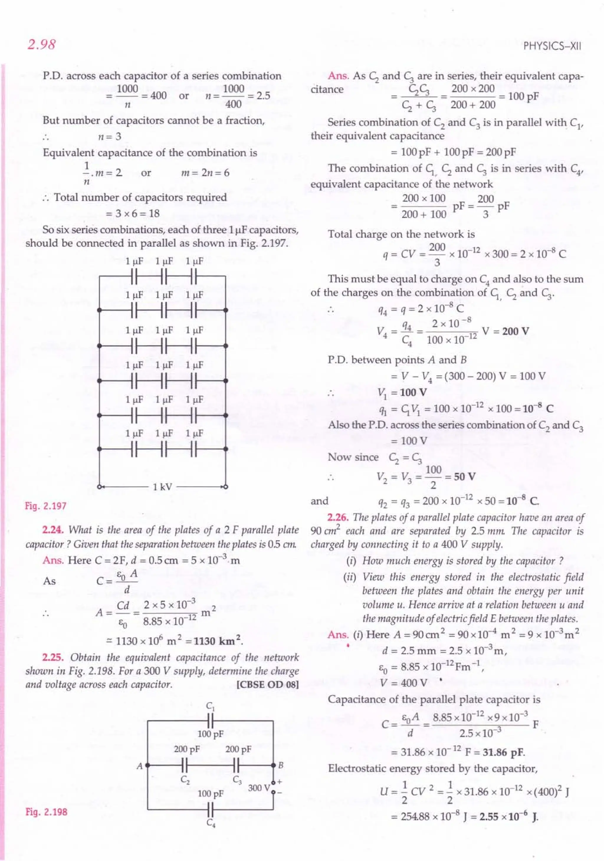
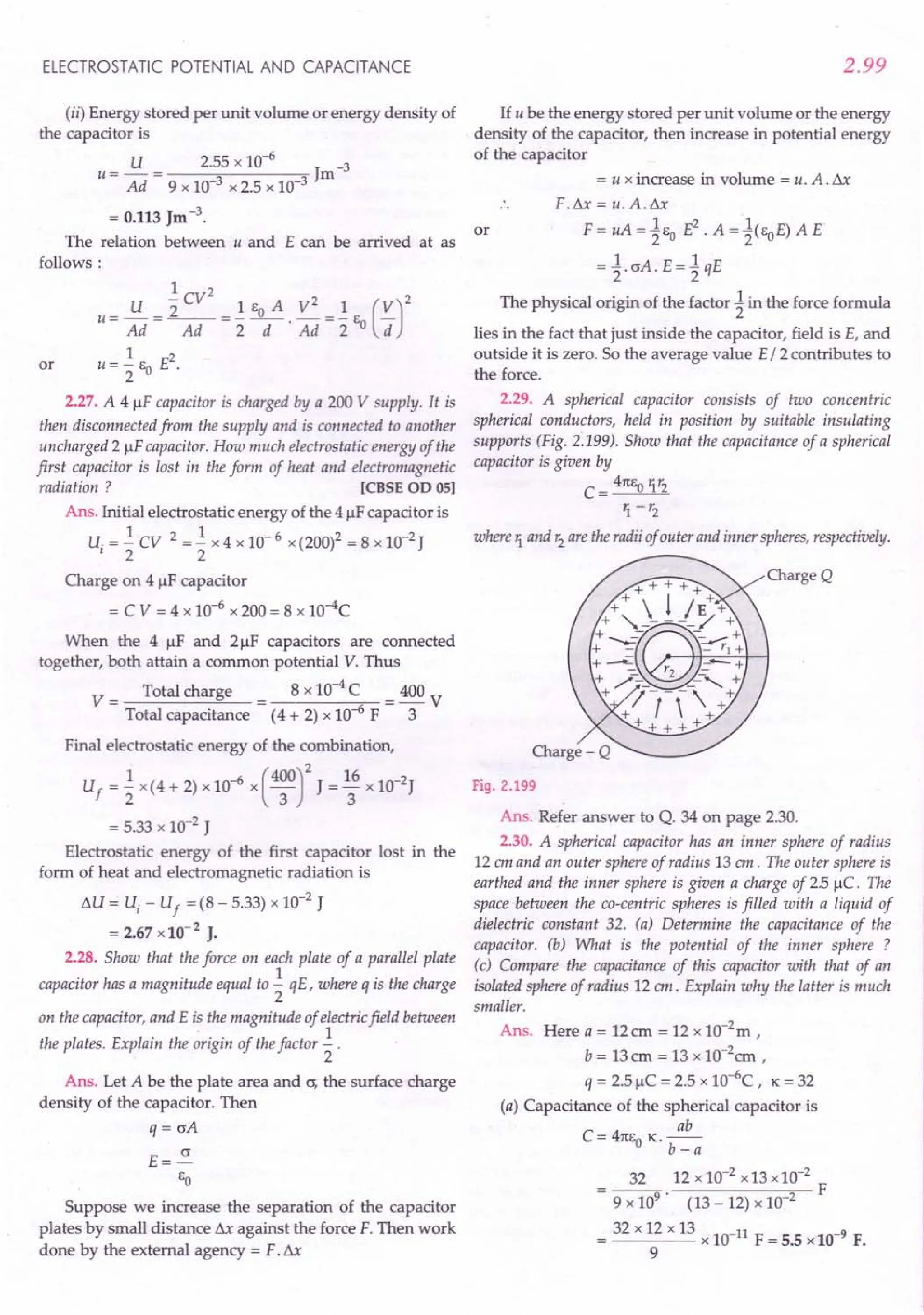
![2.100
(b) Potential of the inner sphere is
q 2.5 x 10⁻⁶
3 2
V = - = 9 V = 0.45 x 10 V = 4.5 x10 V.
C 5.5 x 10-
(c) Capacitance of the isolated sphere of radius 12em is
12 x 10-2
-11
C = 41t EO R = 9 F = 1.3 x10 F.
9 x 10
When an earthed conductor is placed near a charged
conductor, the capacitance of the latter increases. The two
conductors form a capacitor. But the capacitance of an
isolated conductor is always small.
2.31. Answer carefully:
(i) Two large conducting spheres carrying charges Q1
and
Q2
are brought close to each other. Is the magnitude of
electrostatic force between them exactly given by
q Q22 r where r is the distance between their centres?
41t EO r
(ii) If Coulomb's law involved 1Ir3
dependence (instead of
1Ir2), would Gauss' law be still true?
(iii) A small test charge is released at rest at a point in an
electrostatic field configuration. Will it travel along the
line of force passing through that point?
(iv) What is the work done by the field of a nucleus in a
complete circular orbit of the electron? What if the orbit
is elliptical ?
(v) We know that electric field is discontinuous across the
surface of a charged conductor. Is electric potential also
discontinuous there ?
(vi) What meaning would you give to the capacity of a single
conductor?
(vii) Guess a possible reason why water has a much greater
dielectric constant (= 80) than say, mica (= 6).
Ans. (i) No. When the two spheres are brought close to
each other, their charge distributions do not remain
uniform and they will not act as point charges.
(ii) No. Gauss's law will not hold if Coulomb's law
involved 1/ r3 or any other power of r (except 2). In
that case the electric flux will depend upon r also.
(iii) Not necessarily. The small test charge will move
along the line of force only if it is a straight line. The
line of force gives the direction of acceleration, and not
that of velocity.
(iv) Zero. But when the orbit is elliptical, work is done in
moving the electron from one point to the other. How-
ever, net work done over a complete cycle is zero.
(v) No, potential is everywhere constant as it is a
scalar quantity.
(vi) A single conductor is a capacitor with one plate at
infinity. It also possesses capacitance.
(vii) Because of its bent shape and the presence of
two highly polar a - H bonds, a water molecule
possesses a large permanent dipole moment about
0.6 x 10- 29 Cm. Hence water has a large dielectric
constant.
PHYSICS-XII
2.32. A cylindrical capacitor has two co-axial cylinders of
length 15 em and radii 1.5 em and 1.4em. The outer cylinder is
earthed and the inner cylinder is given a charge of 35 /lC
Determine the capacitance of the system and the potential of the
inner cylinder. Neglect end effects (i.e., bending offield lines at
the ends).
Ans. Here L=15 em =0.15 m,
q =3.5 liC =3.5 x 10- 6 C a = 1.4 cm =0.014 rn,
b =1.5 em =0.015 rn
Capacitance of a cylindrical capacitor is given by
21tEo L L
C=-b-= 1 b
In - 2 ~- 2.303 log -
a 41tEo a
0.15 F
2 x 9 x 109 x 2.303 log 0.015
0.014
0.15 x 10⁻⁹
F
18 x 2.303 x 0.03
= 0.1206 x 10⁻⁹
F = 1.2 x10⁻¹⁰
F
Potential,
_ q _ 3.5 x 10⁻⁶
_ 4
V - - - 10 V - 2.9 x10 V.
C 1.2 x 10-
2.33. A parallel plate capacitor is to be designed with a
voltage rating 1kV, using a material of dielectric constant 3
and dielectric strength about 107
Vm-1
. For safety, we would
like the field never to exceed say 10% of the dielectric strength.
What minimum area of the plates is required to have a
capacitance of 50 pF ? [CBSEOD 05]
Ans. Maximum permissible voltage
= lkV = 103
V
Maximum permissible electric field
= 10%of 107
Vrn-1
= 106
Vm-1
:. Minimum separation d required between the plates
is given by
E = V or d = V = 10: = 10- 3 m
d E 10
Capacitance of a parallel plate capacitor is
C= K EoA
d
Cd 50 x 10-12
x 10-3
2
A=--= m
K EO 3 x 8.85 x 10-12
= 18.8 x 10⁻⁴m2 .:::19 cm2.
2.34. Describe schematically the equipotential surfaces corres-
ponding to
(i) a constant electric field in the Z-direction.
(ii) a field that uniformly increases in magnitude but
remains in a constant (say, Z) directions.
(iii) a single positive charge at the origin.
(iv) a uniform grid consisting of long equally spaced
parallel charged wires in a plane.](https://image.slidesharecdn.com/slaroraclass12thphysicsbyrockytrickster-250318042948-c8b51a5a/75/SL-ARORA-CLASS-12TH-PHYSICS-BY-ROCKY-TRICKSTER-pdf-169-2048.jpg)
![ELECTROSTATIC POTENTIAL AND CAPACITANCE
Ans. (i) For a constant electric field in Z-direction,
equipotential surfaces will be planes parallel to XY-planes,
as shown in Fig. 2.200.
iZ
I 7
E1 I 7)Equipotentials
I /.
~-----------------.y
.: a
,
,/
,
,
,
X~
Fig. 2.200
(ii) In this case also, the equipotential surfaces will be
planes parallel to XY-plane. However, as field increases,
such planes will get closer.
(iii) For a single positive charge at the origin, the
equipotential surfaces will be concentric spheres having
origin as their common centre, as shown in Fig. 2.25. The
separation between the equipotentials differing by a
constant potential increases with increase in distance
from the origin.
(iv) Near the grid the equipotential surfaces will have
varying shapes. At far off distances, the equipotential
surfaces will be planes parallel to the grid.
2.35. In a Van de Graaff type generator, a spherical metal shell
is to be a 15 x 106
V electrode. The dielectric strength of the gas
surrounding the electrode is 5 x 10⁷
Vm-1. What is the mini-
mum radius of the spherical shell required? [CBSE OD 08]
Ans. Maximum permissible potential, V = 1.5 x 10⁶
V
For safety, the maximum permissible electric field is
E = 10% of dielectric strength
= 10% of 5 x 10⁷ Vm -1 = 5 x 10⁶ Vm-1
Now for a spherical shell,
V = _1_.3.
47t Eo r
E=_l_ 3...= V
47t EO . r2
r
Minimum radius required is
V 1.5 x 10⁶
V 1
r = - = = 3 x 10- m = 30 em.
E 5 x 10⁶
Vm 1
2.36. A small sphere of radius '1 and charge q1is enclosed by
a spherical shell of radius r2 and charge q2' Show that if q1 is
positive, charge will necessarily flow from the sphere to the shell
(when the two are connected by a wire) no matter what the
charge q2 on the shell is.
Ans. Refer answer to Q. 55 on page 2.67.
2.101
2.37. Answer the following:
(i) The top of the atmosphere is at about 400 kV with respect
to the surface of the earth, corresponding to an electric field that
decreases with altitude. Near the surface of the earth, the field is
about 100 Vm-1. Why do then we not get an electric shock as we
step out of our house into the open? (Assume the house to be a
steel cage so there is no field inside.)
(ii) A man fixes outside his house one evening a two metre
high insulating slab carrying on its top a large aluminium sheet
of area 1m2. Will he get an electric shock if he touches the metal
sheet next morning?
(iii) The discharging current in the atmosphere due to the
small conductivity of air is known to be 1800 A on an average
over the globe. Why then does the atmosphere not discharge
itself completely in due course and become electrically neutral ?
In other words, what keeps the atmosphere charged?
(iv) What are the forms of energy into which the electric
energy of the atmosphere is dissipated during a lightning?
Ans. (i) Normally the equipotential surfaces are
parallel to the surface of the earth as shown in Fig. 2.201.
Now our body is a good conductor. So as we step out into
the open, the original equipotential surfaces of open air
get modified, but keeping our head and the ground at the
same potential and we do not get any electric shock.
300 V 300 V
200 V 200 V
lOOV
77777777777777
Ground
(a)
77777777777777
Ground
(b)
Fig. 2.201
(ii) Yes. The aluminium sheet and the ground form a
capacitor with insulating slab as dielectric. The dis-
charging current in the atmosphere will charge the capa-
citor steadily and raise its voltage. Next morning, if the
man touches the metal sheet, he will receive shock to the
extent depending upon the capacitance of the capacitor
formed.
(iii) The atmosphere is continuously being charged by
thunder storms and lightning bolts all over globe and
maintains an equilibrium with the discharge of the
atmosphere in ordinary weather conditions.
(iv) The electrical energy is lost as (i) light energy
involved in lightning (ii) heat and sound energy in the
accompanying thunder.](https://image.slidesharecdn.com/slaroraclass12thphysicsbyrockytrickster-250318042948-c8b51a5a/75/SL-ARORA-CLASS-12TH-PHYSICS-BY-ROCKY-TRICKSTER-pdf-170-2048.jpg)
![2.102 PHYSICS-XII
Text Based Exercises
~YPE A : VERY SHORT ANSWER QUESTIONS (1 mark each)
1. Define electric potential. Is it a scalar or a vector
quantity? [Punjab01; CBSEaD 06]
2. Define the unit of electric potential. [Punjab02]
3. Write down the relation between electric field and
electric potential at a point.
4. Name the physical quantity whose 51,unit is JC-I
.
Is it a scalar or a vector quantity? [CBSE
aD 2010]
5. Write the 51unit of potential gradient.
6. Define electric potential difference between two
points. Is it scalar or vector? [Punjab01]
7. What do you mean by a potential differenceof 1volt?
8. Write the dimensional formula of potential
difference.
9. 5 J of work is done in moving a positive charge of
0.5 C between two points. What is the potential
difference between these two points? [ISCE9S]
10. A charge of 2 C moves between two points main-
tained at a potential difference of 1 volt. What is the
energy acquired by the charge ?
[!SCE94; CBSED 10C]
11. In a conductor, a point P is at a higher potential
than another point Q. In which direction do the
electrons move?
12. Give two examples of conservative forces.
[Himachal93]
13. How much is the electric potential of a charge at a
point at infinity ?
14. What is the nature of symmetry of the potential of a
point charge ?
15. What are the points at which electric potential of a
dipole has maximum value?
16. What are the points at which electric potential of a
dipole has a minimum value?
17. What is the nature of symmetry of a dipole
potential?
18. What is electrostatic potential energy? Where does
it reside?
19. What is the value of the angle between the vectors
p and E for which the potential energy of an
electric dipole of dipole moment p, kept in an
-4
external electric field E r has maximum value?
[CBSE
SPIS]
-4
20. Write an expression for potential at point P (r )
due to two charges 'h and q2 located at positions
-4 d-4 . I
r I an r 2 respective y.
21. Define electron volt. How is it related to joule?
22. How many electron volts make up one joule?
[Himachal93]
23. Will there be any effect on the potential at a point if
the medium around this point is changed ?
24. What work must be done in carrying an a-particle
across a potential difference of 1 volt ?
25. What is an equipotential surface? Give an example.
[Punjab2000,02; CBSED 03]
26. Why are electric field lines perpendicular at a point
on an equipotential surface of a conductor?
[CBSE
co ISC]
27. Can you say that the earth is an equipotential
surface?
28. What is the geometrical shape of equipotential
surfaces due to a single isolated charge?
[CBSE
D13]
29. What is the shape of the equipotential surfaces for a
uniform electric field? [Punjab01]
30. How much work is done in moving a 500IlCcharge
between two points on an equipotential surface?
[CBSE
D 02]
31. A charge of + 1Cis placed at the centre of a spherical
shell of radius 10 cm. What will be the work done in
moving a charge of + 11lC on its surface through a
distance of 5 cm ?
32. What is the optical analogue of an equipotential
surface?
33. The middle point of a conductor is earthed and its
ends are maintained at a potential difference of
220 V. What is the potential at the ends and at the
middle point?
34. Define capacitance of a conductor.
35. Can there be a potential difference between two
conductors of same volume carrying equal positive
charges?
36. The capacitance of a conductor is 1 farad. What do
you mean by this statement?
37. What is a capacitor? [Punjab96C]](https://image.slidesharecdn.com/slaroraclass12thphysicsbyrockytrickster-250318042948-c8b51a5a/75/SL-ARORA-CLASS-12TH-PHYSICS-BY-ROCKY-TRICKSTER-pdf-171-2048.jpg)
![ELECTROSTATIC POTENTIAL AND CAPACITANCE
38. Write the physical quantity that has its unit
coulomb volt-1. Is it a vector or scalar quantity ?
[CBSE 0 93C, 98]
39. Define capacitance. Give its 51unit.
[CBSE 0 93C ; ISCE 98]
40. Define 51unit of capacitance. [CBSE 00 94]
41. Write the dimensions of capacitance.
42. What is the net charge on a charged capacitor?
43. On what factors does the capacitance of a capacitor
depend?
44. Write two applications of capacitors in electrical
circuits.
45.. In what form is the energy stored in a charged
capacitor?
46. What is the basic purpose of using a capacitor?
47. Write different expressions for the energy stored in
a capacitor.
48. Write down the expression for the capacitance of a
spherical capacitor.
49. The difference between the radii of the two spheres
of a spherical capacitor is increased. Will the capa-
citance increase or decrease? [Punjab 2000]
50. What is a dielectric ?
51. Define dielectric constant in terms of the capa-
citance of a capacitor. [CBSE 0 06]
52. Write down the relation between dielectric constant
and electric susceptibility.
53.
~
Write a relation for polarisation P of a dielectric
material in the presence of an external electric field
~
E.
54.
[CBSEOO 15]
Define dielectric strength of a medium. What is its
value for vacuum ?
55. Where is the knowledge of dielectric strength
helpful?
What is the effect of temperature on dielectric
constant?
An air capacitor is given a charge of 2 J.lC
raising its
potential to 200 V. If on inserting a dielectric
medium, its potential falls to 50 V, what is the
dielectric constant of the medium ?
An uncharged insulated conductor A is brought
near a charged insulated conductor B. What
happens to the charge and potential of B?
[CBSE 00 OlC]
For a given potential difference, does a capacitor
store more or less charge with a dielectric than it
does without a dielectric ?
56.
57.
58.
59.
2.103
60. Can we place a parallel plate capacitor of 1 F
capacity in our house?
61. What is the basic difference between a capacitor
and an electric cell ?
62. Two capacitors of capacitances c; and c; are
connected in parallel. A charge q is given to the
combination. What will be the potential difference
across each capacitor?
63. What is the order of capacitances used in a radio
receiver?
64. Is there any conductor which can take unlimited
charge?
65. A parallel plate capacitor with air between the
plates has a capacitance of 8 pF. What will be the
capacitance if the distance between the plates be
reduced by half and the space between them is
filled with a substance of dielectric constant K = 6?
[CBSE 0 05]
66. A 500J.lCcharge is at the centre of a square of side
10 cm. Find the work done in moving a charge of
10J.lCbetween two diagonally opposite points on
the square. [CBSE 0 08]
67. The graph of Fig. 2.202, shows the variation of the
total energy (E) stored in a capacitor against the
value of the capacitance (C)itself. Which of the two
the charge on the capacitor or the potential used to
charge it is kept constant for this graph?
[CBSE Sample Paper 08]
Fig. 2.202
68. Define the term 'potential energy' of charge' if at a
distance 'r' in an external electric field.
[CBSEOO 09]
69. What is the work done in moving a test charge q
through a distance of 1 cm along the equatorial axis
of an electric dipole? [CBSE 00 09]
70. What is the electrostatic potential due to an electric
dipole at an equatorial point? [CBSE 00 09]
71. A metal plate is introduced between the plates of a
charged parallel plate capacitor. What is its effect
on the capacitance of the capacitor? [CBSE F 09]](https://image.slidesharecdn.com/slaroraclass12thphysicsbyrockytrickster-250318042948-c8b51a5a/75/SL-ARORA-CLASS-12TH-PHYSICS-BY-ROCKY-TRICKSTER-pdf-172-2048.jpg)
![72. A hollow metal sphere of radius 5 em is charged
such that the potential on its surface is 10V:What is
the potential at the centre of the sphere?
[CBSEOD11]
73. In which orientation, a dipole placed in a uniform
electric field is in (i) stable, (ii) unstable equili-
brium ? [CBSE
OD08; D 10]
74. Write the expression for the work done on an
electric dipole of dipole moment p in turning it
from its position of stable equilibrium to a position
....
of unstable equilibrium in a uniform electric field E.
[CBSE
D13C]
75. Two charges 21lC and -21lC are placed at points A
and B, 5 cm apart. Depict an equipotential surface
of the system. [CBSE
D13C] Fig. 2.203
2.104
Answers
PHYSICS-XII
76. What is the amount of work done in moving a
charge around a circular arc of radius r at the centre
of which another point charge is located ?
[CBSE
OD13C]
77. What is the equivalent capacitance, C, of the five
capacitors, connected as shown in Fig. 2.203 ?
[CBSE
SamplePaper2011]
v
1. The electric potential at any point in an electric
field is defined as the amount of work done in
moving a unit positive charge from infinity to that
point against the electrostatic force. It is a scalar
quantity.
2. The SI unit of electric potential is volt. The electric
potential at a point is said to be 1 volt, if 1 joule of
work is done in moving a positive charge of 1
coulomb from infinity to that point against the
electrostatic force.
E= _ dV .
3.
dr
4. Electric potential or potential difference. It is a
scalar quantity.
5. SI unit of potential gradient = Vm-1.
6. The potential difference between two points in an
electric field may be defined as the amount of work
done in moving a unit positive charge from one
point to the other against the electrostatic force. It is
a scalar.
7. The potential difference between two points is said
to be 1 volt if 1 joule of work is done in moving a
positive charge of 1 coulomb from one point to the
other against the electrostatic force.
.. work done ML2T-2
8. Potential difference = =---
charge C
ML2T-2
=0 = [ML2r3 A-I]
AT
9. V = W = ~ =10 V.
q O.5C
••
10. Energy acquired by the charge = qV = 2C x 1V = 2 J.
11. From Q to P.
12. (i) Electrostatic force, (ii) Gravitational force.
13. Zero.
14. The potential of a point charge is spherically
symmetric.
15. At axial points, the electric potential of a dipole has
a maximum positive or negative value.
16. At equatorial points, the electric potential of a
dipole is zero.
17. The dipole potential is cylindrically symmetric.
18. The electrostatic potential energy of a system of
charges may be defined as the work required to be
done to bring the various charges to their respective
positions from infinity.
19. P.E. = -pEcos 9. Clearly, P.E. is maximum when
cos9 = -lor 9 = 180°.
V( 17) = _1_ [ ql + q2 1
4m:o I17 - 171 I I17 - 172 I
Electron volt is the potential energy gained or lost
by an electron in moving through a potential
difference of one volt.
1electron volt = leV = 1.6 x 10⁻¹⁹
J
1J = 6.25 x 10¹⁸eV.
Yes. If the dielectric constant of the medium is
increased, the electric potential will decrease.
24. W = qLW = 2e t1V
= 3.2 x 10-19
C x 1V = 3.2 x 10⁻¹⁹
J.
20.
21.
22.
23.](https://image.slidesharecdn.com/slaroraclass12thphysicsbyrockytrickster-250318042948-c8b51a5a/75/SL-ARORA-CLASS-12TH-PHYSICS-BY-ROCKY-TRICKSTER-pdf-173-2048.jpg)
![2.106
60. No. If d = 1em = 10- 2 m, then area of such a capa-
citor would be
A = Cd = 1 F x 10-
2
m = 109 m 2
Eo 8.85 x 10⁻¹²
C2
N-1
m-
2
This is a plate about 30 km in length and breadth.
61. A capacitor provides electrical energy stored in it.
A cell provides electrical energy by converting
chemical energy into electrical energy.
62. In parallel combination, potential difference is same
across each capacitor.
Net capacitance, C = c; + ~
:. P.D. across each capacitor, V = !L = --q- .
C c; + ~
63. In the power supply, it is 1- 10 /-IFand for tuning
purposes, it is 100/-lF.
64. Yes, the earth because of its large capacitance can
take unlimited charge.
65. With air between the capacitor plates,
E A
Co =-"T-=8pF
With dielectric between the capacitor plates,
C = K Eo A = 2 KCo = 2 x 6 x 8 = 96 pF.
d/2
66. The work done in moving a charge of 10 uC
between two diagonally opposite points on the
square will be zero because these two points will be
equipotential.
67. Energy stored, E = -.! CV2 = -.! Ii
2 2 C
1
When Qis constant, E ex: - , and we get a graph of
C
the type given in the question.
Hence the charge Qon the capacitor is kept constant.
PHYSICS-XII
68. The potential energy of a charge q is the work done
in bringing charge q from infinity to the position r
in the external electric field.
U(r) = qV(r)
69. As potential at any point on the equatorial axis of
an electric dipole is zero, so
W = q ~ V = q( 0 - 0) = o.
70. Zero.
71. The introduction of a metal sheet of thickness t in a
parallel plate capacitor increases its capacitance by
a factor of .s:r where d is the plate separation of
d -t
the capacitor.
72. Potential at the centre
= Potential at the surface = 10V.
73. (i) When the dipole moment p is parallel to the the
-+
electric field E(8 = 0°), the dipole is in stable
equilibrium.
(ii) When the dipole moment p is antiparallel to the
-+
electric field E(8 = 180°), the dipole is in unstable
equilibrium.
74. W = pE(cos~ -cos82
) = pE(cosOO-cos1800)
= pE(l+ 1) = 2pE.
75. See Fig. 2.26 on page 2.15.
76. Zero, because all points of the circular arc will be at
the same potential.
77. C =~, because the combinations of C; and ~ as
well as C4
and Cs have been shorted.
"YPE B : SHORT ANSWER QU ESTIONS (2 or 3 marks each)
1. Distinguish between electric potential and poten-
tial energy and write the relation between them.
[Punjab96C]
2. Define electric potential. Derive an expression for
the electric potential at a distance r from a charge q.
[Punjab99C]
3. Draw a plot showing the variation of (i) electric
field (E)and (ii) electric potential (V) with distance r
due to a point charge Q. [CBSE D 12]
4. Derive an expression for the electric potential due
to an electric dipole. [Haryana01]
5. Derive an expression for the electric potential at a
point along the axis line of the dipole.
[CBSE D 2000, 08 ; OD OlC, 02, 13C]
6. Show mathematically that the electric potential at
any equatorial point of an electric dipole is zero.
[CBSEOD01]
7. Give three differences between the nature of electric
potentials of a single point charge and an electric
dipole.
8. Obtain an expression for the electric potential at a
point due to group of N point charges.](https://image.slidesharecdn.com/slaroraclass12thphysicsbyrockytrickster-250318042948-c8b51a5a/75/SL-ARORA-CLASS-12TH-PHYSICS-BY-ROCKY-TRICKSTER-pdf-175-2048.jpg)
![ELECTROSTATIC POTENTIAL AND CAPACITANCE
9. Obtain an expression for the potential at a point due
to a continuous charge distribution. [CBSE aD 92C]
10. Show that the electric field at any point is equal to
the negative of the potential gradient at that point.
11. Describe how can we determine the electricpotential
at a point from the knowledge of electric field.
12. Two closely spaced equipotential surfaces A and B
with potentials V and V + BV, (where 8V is the
change in V), are kept 81 distance apart as shown in
the figure. Deduce the relation between the electric
B v+ov
~--7V
Fig. 2.204
field and the potential gradient between them. Write
the two important conclusions concerning the
relation between the electric field and electric
potentials. [CBSE D 14C]
13. Show that the amount of work done in moving a
test charge over an equipotential surface is zero.
[Haryana97]
14. Show that the direction of the electric field is
normal to the equipotential surface at every point.
15. Show that the equipotential surfaces are closed
together in the regions of strong field and far apart
in the region of weak field.
16. Sketch equipotential surfaces for
(i) a positive point charge. [CBSE D 2000]
(ii) a negative point charge. [CBSE DOl]
(iii) two equal and opposite charges separated by a
small distance.
(iv) two equal and positive charges separated by a
small distance.
a uniform electric field.
Draw equipotential surfaces
charge Q> O.
(b) Are these surfaces equidistant from each
other? If not, explain why. [CBSE D HC]
18. Draw the equipotential surfaces due to an electric
dipole. Locate the points where the potential due
to the dipole is zero. [CBSE aD 13]
19. Two point charges ql and q2 are located at Ti and
r; respectively in an external electric field E.
Obtain the expression for the total work done in
assembling this configuration. [CBSE D 14C]
(v)
17. (a)
[CBSE D 2000, 01]
due to a point
2.107
20. (a) Depict the equipotential surfaces for a system
of two identical positive point charges placed a
distance'd' apart.
(b) Deduce the expression for the potential energy
of a system of two point charges ql and q2
brought from infinity to the points ?and ~
respectively in the presence of external electric
->
field E.
21.
[CBSE D 10 ; on 15]
Derive an expression for the potential energy of an
->
electric dipole of dipole moment p in an electric
->
field E.
22.
[Himachal02; CBSE D OS]
An electric dipole is held in a uniform electric field
->
E.
(a) Show that the net force acting on it is zero.
(b) The dipole is aligned with its dipole moment p
->
parallel to the field E . Find:
(i) the work done in turning the dipole till its
dipole moment points in the direction
->
opposite to E .
(ii) the orientation of the dipole for which the
torque acting on it becomes maximum.
[CBSE oo 12, 14C]
23. Using Gauss's law, show that electric field inside a
conductor is zero. [CBSE D 2000]
24. Just outside a conductor electric field is perpen-
dicular to the surface. Give reason.
25. Show that the excess charge on a conductor resides
only on its surface.
26. Show that the electric field at the surface of a
charged conductor is given by E= ~ ~, where o is
EO
the surface charge density and ~ is a unit vector
normal to the surface in the outward direction.
[CBSEOD 10]
Or
Derive an expression for the electric field at the
surface of a charged conductor. [CBSE aD 09]
27. Show that electric field is zero in the cavity of
hollow charged conductor.
28. What is electrostatic shielding ? Mention its two
applications.
29. Define electrical capacitance of a conductor. On
what factors does it depend ?
30. Show that the capacitance of a spherical conductor
is proportional to its radius. Hence justify that farad
is a large unit of capacitance. [Himachal96]](https://image.slidesharecdn.com/slaroraclass12thphysicsbyrockytrickster-250318042948-c8b51a5a/75/SL-ARORA-CLASS-12TH-PHYSICS-BY-ROCKY-TRICKSTER-pdf-176-2048.jpg)
![2.108
31. An isolated conductor cannot have a large capa-
citance. Why ?
32. Why does the capacitance of a conductor increase,
when an earth connected conductor is brought near
it ? Briefly explain.
33. What is a capacitor? Explain its principle.
[Punjab2000, 02, 03]
34. Derive an expression for the capacitanceof a parallel
plate capacitor. [CBSE
0 OSC,
14; 00 03]
35. (a) Obtain the expression for the energy stored per
unit volume in a charged parallel plate capacitor.
(b) The electric field inside a + + + + + + + + + + + +
parallel plate capacitor is aOb
E. Find the amount of
work done in moving a
d c
charge q over a closed _
rectangular loop a bed a.
[CBSE
0 14] Fig.2.205
36. Distinguish between polar and non-polar dielec-
trics. Give one example of each.
37. Three capacitors of capacitances ;, C; and C3 are
connected in series. Find their equivalent capa-
citance. [CBSE
0 92,93; Haryana94; Himachal97]
38. Three capacitors of capacitances q. C; and C3 are
connected in parallel. Find their equivalent
capacitance. [CBSE
0 92, 94 ; Himachal99]
39. Deduce the expression for the electrostatic energy
stored in a capacitor of capacitance 'C' and having
charge 'Q'.
How will the (i) energy stored and (ii) the electric
field inside the capacitor be affected when it is
completely filled with a dielectric material of
dielectric constant 'K ? [CBSE
00 08,12]
40. If two charged conductors are touched mutually
and then separated, prove that the charges on them
will be divided in the ratio of their capacitances.
41. Two capacitors with capacity; and C; are charged
to potential V; and V2
respectively and then
connected in parallel. Calculate the common
potential. across the combination, the charge on
each capacitor, the electrostatic energy stored in the
system and the change in the electrostatic energy
from its initial value. [CBSE
SamplePaper08]
42. Explain why the polarization of a dielectric reduces
the electric field inside the dielectric. Hence define
dielectric constant. [CBSE
0 99]
43. Define' dielectric .constant' of a medium. Briefly
explain why the capacitance of a parallel plate capa-
citor increases, on introducing a dielectric medium
between the plates. [CBSE
00 06C]
PHYSICS-XII
44. What is meant by dielectric polarisation ? Hence
establish the relation: K = 1+ X [Haryana01]
45. Two dielectric slabs of dielectric constants Kl and K2
are filled in between the two plates, each of area A,
of the parallel plate capacitor as shown in Fig. 2.206.
Find the net capacitance of the capacitor.
ICBSE
00 05]
DOl
I-- 1/2 ------II-- 1/2 ------I
Fig.2.206
46. A parallel plate capacitor of capacitance C is
charged to a potential V. It is then connected to
another uncharged capacitor having the same
capacitance. Find out the ratio of the energy stored
in the combined system to that stored initially in
the single capacitor. ICBSE
0014]
47. If two similar plates, each of area A having surface
charge densities + cr and - cr are separated by a
distance d in air, write expressions for: (I) The
electric field between the two plates (iI) The
potential difference between the plates (iil) The
capacitance of the capacitor so formed.
ICBSE OD 07]
48. Explain, using suitable diagrams, the difference in
the behaviour of a (i) conductor and (ir) dielectric in
the presence of external electric field. Define the
terms polarization of a dielectric and write its
relation with susceptibility. ICBSE
0 15]
49. A capacitor is charged with a battery and then its
plate separation is increased without disconnecting
the battery. What will be the change in
(a) charge stored in the capacitor?
(b) energy stored in the capacitor?
(c) potential difference across the plates of the
capacitor?
(d) electric field between the plates of the
capacitor? [CBSE
SamplePaper2011]
50. The charges ql = 3 flF,
q2 = 4 flF and q3 = - 7 flF
are placed on the
circumference of a circle of
radius 1.0 m, as shown in
Fig. 2.207. What is the
value of charge q4 placed
on the same circle if the
potential at centre, Vc = O? Fig.2.207
IISCE
03]](https://image.slidesharecdn.com/slaroraclass12thphysicsbyrockytrickster-250318042948-c8b51a5a/75/SL-ARORA-CLASS-12TH-PHYSICS-BY-ROCKY-TRICKSTER-pdf-177-2048.jpg)
![ELECTROSTATIC POTENTIAL AND CAPACITANCE
51. Two thin concentric shells of radii 1. and r2 (r2 > 1.)
have charges ql and q2. Write the expression for the
potential at the surface of inner and outer shells.
[CBSE 00 13 C]
52. (a) A charge + Q is placed on a large spherical
conducting shell of radius R Another small con-
ducting sphere of radius r carrying charge 'if is
introduced inside the large shell and is placed at its
centre. Find the potential difference between two
points, one lying on the sphere and the other on the
shell.
Answers
2.109
(b) How would the charge between the two flow, if
they are connected by a conducting wire? Name
the device which works on this fact. [CBSE 00 09]
53. Briefly describe discharging action of sharp points
(or corona discharge).
54. Draw a labelled schematic diagram of a Van-de-
Graaff generator. State its working principle.
Describe briefly how it is used to generate high
voltages. [CBSE 0 13 C]
••
1. Refer to points 3 and 11 of Glimpses.
2. Refer answer to Q. 2 on page 2.2.
3. See Fig. 2.3 on page 2.2.
4. Refer answer to Q. 5 on page 2.3.
5. Refer answer to Q. 3 on page 2.2.
6. Refer answer to Q. 4 on page 2.3.
7. Refer answer to Q. 6 on page 2.3.
8. Refer answer to Q. 7 on page 2.4.
9. Refer answer to Q. 8 on page 2.4.
10. Refer answer to Q. 10 on page 2.11.
11. Refer answer to Q. 11 on page 2.12.
12. Work done in moving a unit positive charge
through distance ol,
Exol =VA
- VB = V -(V + OV) =-OV
E=- OV
01
For conclusions, refer answer to Q. 10 on page 2.12.
13. Refer answer to Q. 14 on page 2.14.
14. Refer answer to Q. 14 on page 2.14.
15. Refer answer to Q. 14 on page 2.14.
16. Refer answer to Q. 15 on page 2.15.
17. (a) See Fig. 2.25 on page 2.15.
dV dV
(b) As E = - dr or dr = -r:
1
:. For constant dV, dr oc - oc r2
E
Hence the spacing between the equipotential
surface will increase with the increase in distance
from the point charge.
18. See Fig. 2.26 on page 2.15. The electric potential is
.zero at the equatorial points of the dipole.
19. Refer answer to Q. 20 on page 2.17.
20. (a) See Fig. 2.27 on page 2.16.
(b) Refer answer. to Q. 20 on page 2.17.
21. Refer answer to Q. 22 on page 2.18.
22. (a) Refer answer to Q. 40 on page 1.41 of chapter 1.
n n
(b) (i) W = J,d8 = JpEsin 8 = pE[-cos era = -2pE.
a a
(ii) As , = pEsin 8, so , is maximum when 8 = 90°.
23. Refer answer to Q. 25 on page 2.24.
24. Refer answer to Q. 25 on page 2.24.
25. Refer answer to Q. 25 on page 2.24.
26. Refer answer to Q. 25 on page 2.24.
27. Refer answer to Q. 25 on page 2.24.
28. Refer answer to Q. 26 on page 2.25.
29. Refer answer to Q. 27 on page 2.26.
30. Refer answer to Q. 29 on page 2.26.
31. Refer answer to Q. 30 on page 2.28.
32. Refer answer to Q. 31 on page 2.28.
33. Refer answer to Q. 31 on page 2.28.
34. Refer answer to Q. 33 on page 2.29.
35. (a) Refer answe~ to Q. 40 on page 2.49.
(b) E.Lab and E.Ldc, so Wab = 0 and Wed = O.
Also, Wbc = - Wda
Total work done in moving charge q over the closed
loop abcda,
W = Wab + Wbc :+- Wcd + Wda
= 0- Wda + 0+ Wda = O.
36. Refer answer to Q. 43 on page 2.56.
37. Refer answer to Q. 36 on page 2.33.
38. Refer answer to Q. 37 on page 2.33.
. 39. Refer answer to Q. 38 page 2.48.
When the capacitor is completely filled with a
dielectric material and for constant charge Q,
C = KCU and V = Va / K](https://image.slidesharecdn.com/slaroraclass12thphysicsbyrockytrickster-250318042948-c8b51a5a/75/SL-ARORA-CLASS-12TH-PHYSICS-BY-ROCKY-TRICKSTER-pdf-178-2048.jpg)
![2.110
(i) U=!:CV2 =!:(KCu)(VO]2=.!..!CuV02 = Uo
2 2 K K2 K
(ii) E = fu
~
40. Refer answer to Q. 41 on page 2.49.
41. Refer answer to Q. 42 on page 2.49.
42. Refer answer to Q. 45 on page 2.57.
43. Refer to point 35 of Glimpses on page 2.116.
44. Refer answer to Q. 47 on page 2.58.
45. The given arrangement is equivalent to a parallel
combination of two capacitors each with area A I 2
and plate separation d. Hence the net capacitance of
the resulting capacitor is
C=c;+c;
EO (AI 2) K} EO (AI 2) K2
= +~---..=.
d d
46. Initial energy stored in the single capacitor
= !:CV2 =!: q2
2 2C
Capacitance of the combined (parallel) system
= C+ C=2C
As the total charge q remains the same, so
Final energy stored in the combined system = !:i....
22C
47.
Final energy =!: =1 : 2.
Initial energy 2
(i) Electric field at points between the two plates,
E=~+~=~.
2ea 2Eo EO
(ii) Potential difference between the plates,
ad
V= Ed=-.
EO
48.
(iii) Capacitance of the capacitor so formed,
C=..i=~= EoA.
V ad I EO d
Refer answer to Q. 43 on page 2.56.
Polarisation of a dielectric. The induced dipole
moment set up per unit volume of a dielectric when
PHYSICS-XII
placed in an external electric field is called
polarisation. For linear isotropic dielectrics,
~ ~
P = EOXe E
where Xe is the electric susceptibility of the
dielectric medium.
49. C=EoA.
d
When d is increased, C decreases.
(a) q = CV decreases due to the decrease in the
value of C.
(b) U = !:CV2 decreases due to the decrease in the
2
value of C.
(c) V remains unchanged because' the battery
remains connected.
(d) E = V I d decreases due to the increase in the
value of d.
SO. As Vc = 0
:. _1_ [ !!1.+ q2 + q3 + q4 ] = 0
4m,0 r r r r
or Ih + q2 + q3 + q4 = 0
or 3 + 4 - 7 + q4 = 0
or q4 = O.
51. Potential at the surface of inner shell,
"t = Potential due to its own charge q}
+ Potential due to charge q2 on outer shell
- 4:EO ( :: + :: J
Potential at the surface of outer shell
V2
= Potential due to charge q} on inner shell
_ 4:J~n:~: rtochargeq, onoutershell
52. Refer answer to Q. 55 on page 2.67.
53. Refer answer to Q. 54 on page 2.67.
54. Refer answer to Q. 56 on page 2.67.
~YPE C : LONG ANSWER QUESTIONS (5 marks each)
1. Find the expression for the electric field intensity
and the electric potential, due to a dipole at a point
on the equatorial line. Would the electric field be
necessarily zero at a point where the electric
potential is zero ? Give an example to illustrate
your answer. ICBSE Sample Paper 2011]
2. Define electrostatic potential energy of a charge
system. Derive an expression for the potential energy
of a system of three point charges. Generalise the
result for a system of N point charges.](https://image.slidesharecdn.com/slaroraclass12thphysicsbyrockytrickster-250318042948-c8b51a5a/75/SL-ARORA-CLASS-12TH-PHYSICS-BY-ROCKY-TRICKSTER-pdf-179-2048.jpg)
![ELECTROSTATIC POTENTIAL AND CAPACITANCE
3. Define the term electric dipole moment. Derive an
expression for the total work done in rotating the
dipole through an angle e in uniform electric field
.....
E. [CBSE OD93, 95 ; D 96C)
4. Derive an expression for the potential energy of an
electric dipole placed in a uniform electric field.
Hence discuss the conditions of its stable and
unstable equilibrium.
5. Explain the principle of a capacitor. Derive an
expression for the capacitance of a parallel plate
capacitor. [CBSE D 92, 94]
6. Obtain the expression for the capacitance of a
parallel plate capacitor.
Three capacitors of capacitances C1, Cz and c; are
connected (i) in series, (ii) in parallel. Show that the
energy stored in the series combination is the same
as that in the parallel combination. [CBSE OD03]
7. Deduce an expression for the total energy stored in
a parallel plate capacitor and relate it to the electric
field. [CBSE F 94C)
8. (a) Derive the expression for the energy stored in a
parallel plate capacitor. Hence obtain the
expression for the energy density of the electric
field.
(b) A fully charged parallel plate capacitor is
connected across an uncharged identical
capacitor. Show that the energy stored in the
combination is less than that stored initially in
the single capacitor. [CBSE OD15]
9. Define the terms (i) capacitance of a capacitor
.(ii) dielectricstrength of a dielectric.When a dielectric
is inserted between the plates of a charged parallel
plate capacitor, fully occupying the intervening
region, how does the polarization of the dielectric
medium affect the net electric field ? For linear
dielectrics, show that the introduction of a
dielectric increases its capacitance by a factor K.
characteristic of the dielectric. [CBSE D OSC)
Answers
2.111
10. Find the expression for the capacitance of a parallel
plate capacitor of area A and plate separation d if
(i) a dielectric slab of thickness t and (ii) a metallic
slab of thickness t, where (t < d) are introduced one
by one between the plates of the capacitor. In which
case would the capacitance be more and why?
[CBSE Sample Paper 2011]
11. What is a dielectric? A dielectric slab of thickness t
is kept between the plates of a parallel plate
capacitor separated by distance d. Derive the
expression for the capacitance of the capacitor for
t «d. [Himachal 02 ; CBSE D 93 ; OD0lC)
12. (a) Show that in a parallel plate capacitor, if the
medium between the plates of a capacitor is filled
with an insulating substance of dielectric constant
K. its capacitance increases. (b) Deduce the
expression for the energy stored in a capacitor of
capacitance Cwith charge Q. [CBSE D 09C)
13. (a) A small sphere, of radius 'o', carrying a positive
charge q, is placed concentrically inside a larger
hollow conducting shell of radius b(b> a). This
outer shell has a charge Q on it. Show that if these
spheres are connected by a conducting wire, charge
will always flow from the inner sphere to the outer
sphere, irrespective of the magnitude of the two
charges. [CBSE F 15]
(b) Name the machine which makes use of this
principle. Draw a simple labelled line diagram of
this machine. What 'practical difficulty' puts on
upper limit on the maximum potential difference
which this machine can built up ?
[CBSE D 09C ; OD14]
14. Explain the principle of a device that can build up
high voltages of the order of a few million volts.
Draw a schematic diagram and explain the working
of this device.
Is there any restriction on the upper limit of the
high voltages set up in this machine? Explain.
[CBSE D 12]
•
1. For derivation of electric field intensity at
equatorial point of a dipole, refer answer to Q. 38
on page 1.40of chapter 1.
1 P
El,qua = 41tEo (r2 + a2 )3/2
For derivation of electric potential at an equatorial
point of a dipole, refer answer to Q. 4 on page 2.3 of
chapter 2.
Vequa = 0
No, the electric field may not be necessarily zero at
a point where the electric potential is zero. For
example, the electricpotential at an equatorial point of
a dipole is zero, while electric field is not zero.
2. Refer answer to Q. 18 on page 2.16.
3. Refer answer to Q. 22 on page 2.18.
4. Refer answer to Q. 22 on page 2.18.
5. Refer answer to Q. 31 on page 2.28 and Q. 33 on
page 2.29.](https://image.slidesharecdn.com/slaroraclass12thphysicsbyrockytrickster-250318042948-c8b51a5a/75/SL-ARORA-CLASS-12TH-PHYSICS-BY-ROCKY-TRICKSTER-pdf-180-2048.jpg)
![2.112
6. Refer answer to Q. 33 on page 2.29 and Q. 39 on
page 2.48.
7. Refer answer to Q. 38 on page 2.48 and Q. 40 on
page 2.48.
8. (a) Refer answer to Q. 38 on page 2.48 and Q. 40 on
page 2.48.
(b) Refer to the solution of Example 75 on page 2.52.
9. Refer answer to Q. 45 on page 2.57 and Q. 49 on
page 2.59.
10. For derivation, refer answers to Q. 49 on page 2.59
and Q. 50 on page 2.60.
EoA
Cdielectric = t
d=t +-
K
C = EOA
metal d=t
Clearly, Cmetal > Cdielectric
[For metal, K = 00 1
PHYSICS-XII
11. Refer answer to Q. 49 on page 2.59.
12. (a) Refer answer to Q. 49 on page 2.59.
(b) Refer answer to Q. 38 on page 2.48.
13. (a) Refer answer to Q. 55 on page 2.67
(b) A Van-de-Graaff generator works on this prin-
ciple. See Fig. 2.130. The potential on the outer
surface of its metallic shell cannot exceed the
breakdown field of air (=::3x10⁶Ym-l)
because then the charges begin to leak into air.
This puts the limit on the potential difference
which the machine can built up.
14. The device is Van de Graff generator. For its principle
and working, refer answer to Q. 56 on page 2.67.
Yes, there is a restriction on the upper limit of the
high voltages set up in the Van de Graaff generator.
The high voltages can be built up only upto the
breakdown field of the surrounding medium .
.l'rYPE 0 : VALUE BASED QUESTIONS (4 marks each)
1. Immediately after school hour, as Birnla with her
friends carne out, they noticed that there was a
sudden thunderstorm accompanied by the
lightning. They could not find any suitable place for
shelter. Dr. Kapoor who was passing thereby in his
car noticed these children and offered them to corne
in his car. He even took care to drop them to the
locality where they were staying. Birnla's parents,
who were waiting, saw this and expressed their
gratitude to Dr. Kapoor. [CBSE00 lSC]
(a) What values did Dr. Kapoor and Birnla's
parents display?
(b) Why is it considered safe to be inside a car
especially during lightning and thunder-
storm ?
(c) Define the term' dielectric strength'. What does
this term signify ?
Answers
2. One evening, Pankaj outside his house fixed a two
metre high insulating slab and attached a large
aluminium sheet of area 1m 2 over its top. To his
surprise, next morning when he incidently touched
the aluminium sheet, he received an electric shock.
He got afraid. He narrated the incident to his
Physics teacher in the school who explained him
the reason behind it.
Answer the following questions based on the above
information:
(a) What are the values being displayed by
Pankaj?
(b) What may be the reason behind the electric
shock received by Pankaj ?
•
1. (a) Dr. Kapoor displayed helpfulness, empathy and
scientific temper.
Bimla parents displayed gratefulness and
indebtedness.
(b) It is safer to sit inside a car during a thunder-
storm because the metallic body of the car
becomes an electrostatic shielding from
lightning.
(c) The maximum electric field that a dielectric
medium can withstand without break-down of
its insulating property is called its dielectric
strength. It signifies the maximum electric field
upto which the dielectric can safely play its role.
2. (a) Keen observer and curiosity.
(b) The aluminium sheet and the ground form a
capacitor alongwith the insulating slab. The
discharging current of the atmosphere charges
the capacitor steadily and raises its voltage. So,
when Pankaj touches the aluminium sheet, he
receives an electric shock.](https://image.slidesharecdn.com/slaroraclass12thphysicsbyrockytrickster-250318042948-c8b51a5a/75/SL-ARORA-CLASS-12TH-PHYSICS-BY-ROCKY-TRICKSTER-pdf-181-2048.jpg)
![Electrostatic Potential and Capacitance
GLIMPSES
1. Potential difference. The potential difference
between two points is defined as the amount of
work done in bringing a unit positive charge
from one point to another against the electro-
static forces.
.. Work done
Potential difference =----
Charge
_ _ WAB
VAB-VB-VA ---
q
or
2. 51 unit of potential difference is volt (V). The
potential difference between two points in an
electric field is said to be 1volt if 1joule of work
has to be done in moving a positive charge of 1
coulomb from one point to the other against the
electrostatic forces.
1 V = 1JCI
= 1 Nm CI
3. Electric potential. It is defined as the amount of
work done in bringing a unit positive charge
from infinity to the observation point against
the electrostatic forces.
Work done
Electric potential
Charge
or V=W
q
Electric potential is a scalar quantity.
4. 51 unit of electric potential is volt. The electric
potential at a point in an electric field is said to be
1 volt if one joule of work has to be done in
moving a positive charge of 1 coulomb from
infinity to that point against the electrostatic
forces.
5. Electric potential due to a point charge. The
electric potential of a point charge q at distance r
from it is given by
1 q
V=--.-
41t 1:0 . r
i.e-.
,
1
Voc-
r
It is spherically symmetric.
6. Electric potential due to a dipole. Electric potential
at a point having position vector r, due to a
dipole of moment p at the origin is given by
--+ --+ 8
V- 1 p.r_ 1 pcos
- 41tl:o ·7-41tl:o -,:;.--
At points on the axial line of the dipole
(8 =Ooor 180°),
V. = +_1_ E
axial - 41t I: .,:;.
a
At points on the equatorial line of the dipole
(8 =90°),
Vequa =0.
7. Electric potential due to a group of N point
charges. If rl, r2, r3... rN are the distances of N
point charges from the observation point, then
V = _1_ [ qi + q2 + q3 + ....+ qN ]
41tl:o 't ~ ~ rN
8. Determination of electric field from electric
potential. The rate of change of potential with
distance is called potential gradient. Electric
(2.113)](https://image.slidesharecdn.com/slaroraclass12thphysicsbyrockytrickster-250318042948-c8b51a5a/75/SL-ARORA-CLASS-12TH-PHYSICS-BY-ROCKY-TRICKSTER-pdf-182-2048.jpg)
![2.114
field at any point is equal to the negative of the
potential gradient at that point
E=- dV
dr
SI unit of electric field = Vm-1
-7
The direction of E is in the direction of steepest
decrease of potential.
9. Determination of electric potential from electric
field. The electric potential at a point having
position vector t is given by
r -7 -7
V =- f E . dr
00
10. Equipotential surface. Any surface that has
same electric potential at every point on it is
called an equipotential surface. The surface of a
charged conductor is an equipotential surface.
Some of the important properties of equi-
potential surface are as follows :
(i) No work is done in moving a test charge
over an equipotential surface.
(ii) Electric field is always normal to the
equipotential surface at every point.
(iii) Equipotential surfaces are close together in
the regions of strong field and farther apart
in the regions of weak field.
(iv) No two equipotential surfaces can intersect
each other.
11. Electric potential energy. The electric potential
energy of a system of point charges is defined as
the amount of work done in assembling the
charges at their locations by bringing them in,
from infinity.
P.E. of a charge = Charge x Electric potential
at the given point
It is measured in joule G) or electron volt (eV).
1 eV = 1.6 x 10⁻¹⁹ J
12. Potential energy of a system of two point
charges. If two point charges q1 and q2 are
separated by distance r12 ' then their potential
energy is
U=_l_. q1 q2
41t So r12
PHYSICS-XII
13. Potential energy of a system of three point
charges. It is given by
U= _1_ [ q1 q2 + q2 q3 + q3 q1 ]
41t So '12 r23 r31
14. Potential energy of N point charges. It is given
by
U=_l_ L qj qj
41t So All pairs ';j
15. Potential energy of a dipole in a uniform electric
field. It is equal to the amount of work done in
turning the dipole from orientation 91 to 92 in
the field E.
U = - pE (cos 92 - cos 91)
If initially the dipole is perpendicular to the
field E, 91 =90° and 92 = 9 (say), then
-7 -7
U = - pE cos 9 = - P . E
When 9 =0°, U = - pE i.e., the potential energy
of the dipole is minimum. The dipole is in stable
equilibrium.
When 9 =90°, U =0
When 9 =180°, U =+ pE
i.e., the potential energy of the dipole is
maximum. The dipole is in unstable equilibrium.
16. Conductors and insulators. Conductors are the
substances which allow large scale physical
movement of electric charges through them
when an external electric field is applied. They
contain a large number of free electrons.
Insulators are the substances which do not
allow physical movement of electric charges
through them when an external electric field is
applied. They contain a negligibly small
number of free charge carriers.
17. Electrostatic properties of a conductor. When
placed in an electrostatic field, a conductor
shows the following properties:
(i) Net electrostatic field is zero in the interior
of a conductor.
(ii) Just outside the surface of a conductor,
electric field is normal to the surface.](https://image.slidesharecdn.com/slaroraclass12thphysicsbyrockytrickster-250318042948-c8b51a5a/75/SL-ARORA-CLASS-12TH-PHYSICS-BY-ROCKY-TRICKSTER-pdf-183-2048.jpg)
![3.2
The orders of magnitude of some electric currents
we come across in daily life are as follows:
Current in a domestic appliance ~ 1A
Current carried by a lightning ~ 104
A
Current in our nerves =-10-6
A = 1~A.
4.. Distinguish between conventional and electronic
currents.
Conventional and electronic currents. By con-
vention, the direction of motion of positive charges is
taken as the direction of electric current. However, a
negative charge moving in one direction is equivalent to
an equal positive charge moving in the opposite
direction, as shown in Fig. 3.1. As the electrons are
negatively charged particles, so the direction of electronic
current (i.e., the current constituted by the flow of
electrons) is opposite to that of the conventional
current.
Conventional current
~
Electronic current
••
~I
Fig. 3.1 Flow of negative charge is equivalent to the flow of
positive charge in the opposite direction.
5. Is electric current a scalar or vector quantity ?
Electric current is a scalar quantity. Although
electric current has both magnitude and direction, yet
it is a scalar quantity. This is because the laws of
ordinary algebra are used to add electric currents and
the laws of vector addition are not applicable to
J.ne addition of electric currents. For example, in
(Fig. 3.2, two different currents of 3 A and 4 A flowing
in two mutually perpendicular wires AO and BO meet
at the junction 0 and then flow along wire Oc.
The current in wire OC is 7 A which is the scalar
addition of 3 A and 4 A and not 5 A as required by
vector addition.
A
3A
90° <'>-0--1--- C
7A
4A
B
Fig. 3.2 Addition of electric currents is scalar.
PHYSICS-XII
Formulae Used
1. Electric current = Charge or I = !i
Time t
ne
2. As q = ne, so I = -
t
3. In case of an electron revolving in a circle of radius
rwith speed v, period of revolution of the electron is
T = 21tr
v
Frequency of revolution, v = 2 = ~
T Zrtr
Current at any point of the orbit is
I = Charge flowing in 1 revolution
x No. of revolutions per second
or I = e v = 3!!.- .
21tr
Units Used
Electric charge is in coulomb (C), time in second
(s), and current in ampere (A)
Constant Used
Charge on an electron, e = 1.6 x 1O-19
c.
Example 1. 1020
electrons, each having a charge of
1.6 x 10⁻¹⁹
C, passfrom apoint A towards another point Bin
0.1 s. What is the current in ampere? What is its direction?
Solution. Here n = 1020
, e = 1.6 x 10 -19 C, t = 0.1 s
Current,
The direction of current is from B to A.
Example 2. Show that one ampere is equivalent to aflow of
6.25 x 10¹⁸
elementary charges per second. [CaSE D 92C]
Solution. Here 1=1 A, t = 1 s, e = 1.6 x 10⁻¹⁹
C
As [=!i=ne
t t
umber of electrons,
li 1x1 u
n = - = 19 = 6.25 x 10 .
e 1.6 x 10-
Example 3. How many electrons pass through a lamp in
one minute, if the current is 300 mA ?
[Himachal 95 ; Punjab 02]
Solution. I = 300 mA = 300 x 10-3 A,
t = 1 minute =60 s, e = 1.6 x 10⁻¹⁹
C
As [=!i=ne
t t](https://image.slidesharecdn.com/slaroraclass12thphysicsbyrockytrickster-250318042948-c8b51a5a/75/SL-ARORA-CLASS-12TH-PHYSICS-BY-ROCKY-TRICKSTER-pdf-187-2048.jpg)
![CURRENT ELECTRICITY
.', Number of electrons,
. n = It = 300 x 10-
3
x 60 = 1.125 x 10²⁰
e 1.6 x 10⁻¹⁹
Example 4. How many electrons per secondflow through a
filament of a 120 V and 60 W electric bulb? Given electric
power is the product of voltage and current.
Solution. Here V = 120 V, P = 60 W, t = 1 s
P 60
As P = VI, therefore, I = - = - = 0.5 A
V 120
Number of electrons,
It 0.5 xl 18
n = - = 19 = 3.125 x 10 .
e 1.6 x 10-
Example 5. In the Bohr model of hydrogen atom, the
electron revolves around the nucleus in a circular path of
radius 5.1 x 10 -11m at afrequency of6.8 x 1015revolutions
per second. Calculate the equivalent current.
Solution. Here r = 5.1 x 10⁻¹¹
m,
v =6.8 x 10¹⁵ rps, e =1.6 x 10⁻¹⁹ C
Current,
1= e v = 1.6 x 10-19 x 6.8 x 1015 = 1.088 x 10⁻³ A.
Example 6. In a hydrogen atom, an electron moves in an
orbit of radius 5.0 x 10⁻¹¹
m with a speed of 2.2 x 10⁶
ms-1
.
Find the equivalent current. (Electronic charge = 1.6 x 10⁻¹⁹
coulomb). [Roorkee 84]
Solution. Here r = 5.0 x 10⁻¹¹
m,
v=2.2x10⁶ms-1
, e=1.6xlO-19
C
Period of revolution of electron,
T=2rrr =2rrx5.0x10-
11
s
v 2.2 x 10⁶
1 2.2 x 10⁶
Frequency, v = - = -----,.,
T 2rr x 5.0 x 10 11
17
2.2x7x10 =7x10¹⁵s-1
2x22x5
Current, 1= e v = 1.6 x 10-19 x 7 x 1015
= 1.12 x 10⁻³ A.
Example 7. Figure 3.3 shows a plot of current I through
the cross-section of a wire over a time interval of10 s. Find
the amount of I(A)
charge that flows
through the wire 5
during this time
period.
[CBSE00 lSC]
5 10
Fig. 3.3
3.3
t (s)
Solution. Amount of charge that flows in 10 s
= Area under the 1- t graph
= ~ x 5 x 5 + (10 - 5) 5 = 37.5 C
Example 8. The amount of charge passing through cross-
section of a wire is q (t) = at2
+ bt + c .
(i) Write the dimensional formulae for a, band c.
(ii) If the values of a, band c in SI units are 5, 3 and 1
respectively, find the value of current at t = 5second.
Solution. (i) Given q (t) = at2
+ bt + c
Dimension of a =[t~] = ~; = Ar1
Dimension of b = [7]= ~T = A
Dimension of c = [q] = AT
(ii) Current, 1= dq = ~ (at2
+ bt + c) =2at + b
dt dt
At t = 5 s, I= 2 x 5 x 5 + 3 = 53 A.
rproblems For Practice
1. One billion electrons pass from a point P towards
another point Q in 10-3
S . What is the current in
ampere? What is its direction?
(Ans. 1.6 x 10⁻⁷
A, direction of
current is from Q to P)
2. If 2.25 x 10²⁰
electrons pass through a wire in one
minute, find the magnitude of the current flowing
through the wire. [Punjab 02] (Ans. 0.6 A)
3. A solution of sodium chloride discharges
6.1 x Hy6 Na + ions and 4.6 x 10¹⁶Cl" ions in 2 s. Find
the current passing through the solution.
(Ans. 8.56 x 10⁻³ A)
4. An electric current of 2.0I!Aexists in a discharge tube.
How much charge flows across a cross-section of
the tube in 5 minutes? (Ans. 6.0 x 10⁻⁴
C)
5. In a hydrogen atom, the electron makes about
0.6 x Hy6 revolutions per second around the nucleus.
Determine the average current at any point on the
orbit of the electron. (Ans. 0.96 mA)
6. An electron moves in a circular orbit of radius 10 em
with a constant speed of 4.0 x 10⁶ ms-1
. Determine
the electric current at a point on the orbit.
(Ans. 1.02 x 10⁻¹²
A)
7. In a hydrogen discharge tube, the number of
protons drifting across a cross-section per second is
1.1 x 10¹⁸
, while the number of electrons drifting in
the opposite direction across another cross-section
is 3.1 x 10¹⁸
per second. Find the current flowing in
the tube. (Ans. 0.672 A)](https://image.slidesharecdn.com/slaroraclass12thphysicsbyrockytrickster-250318042948-c8b51a5a/75/SL-ARORA-CLASS-12TH-PHYSICS-BY-ROCKY-TRICKSTER-pdf-188-2048.jpg)
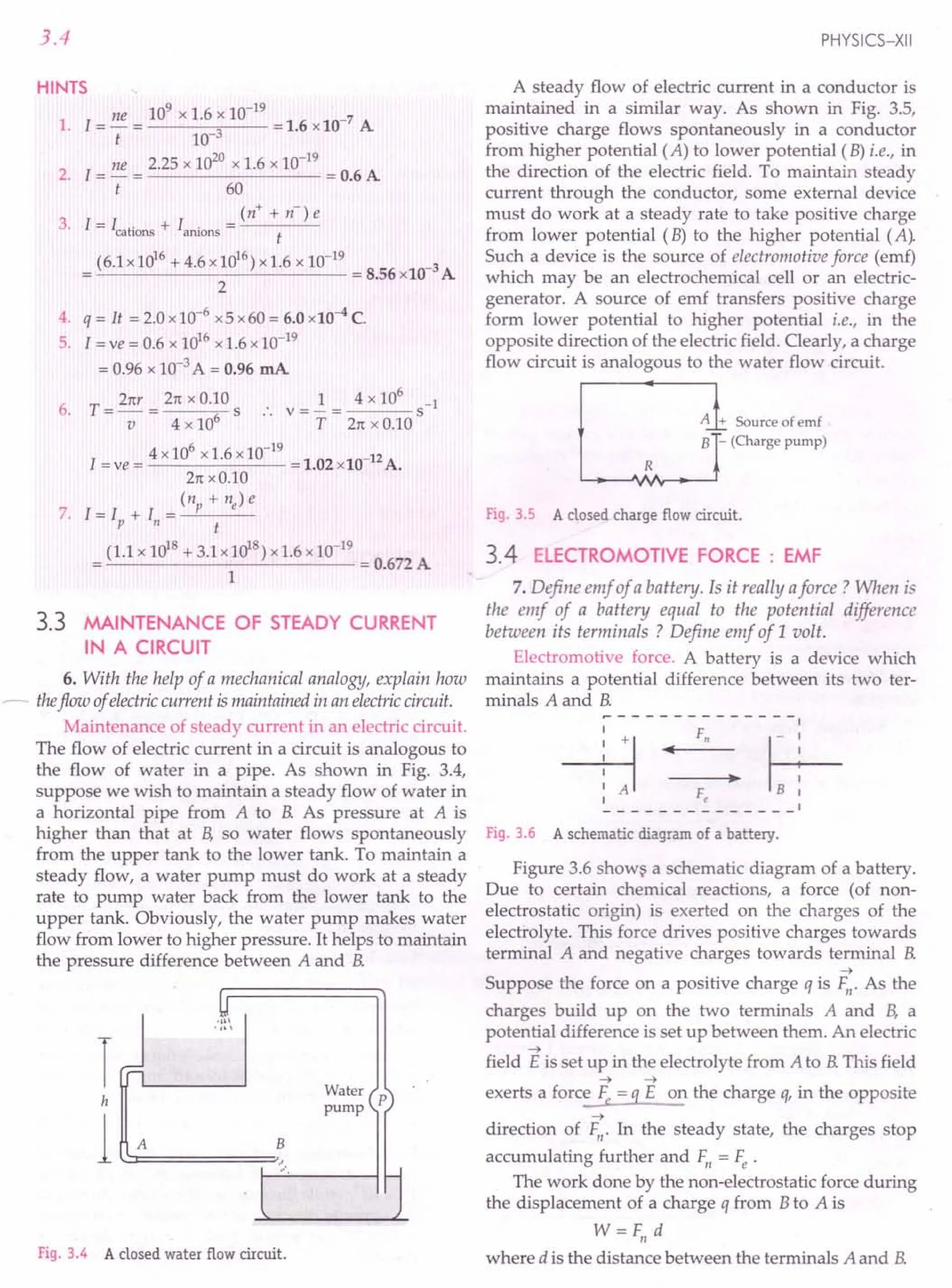
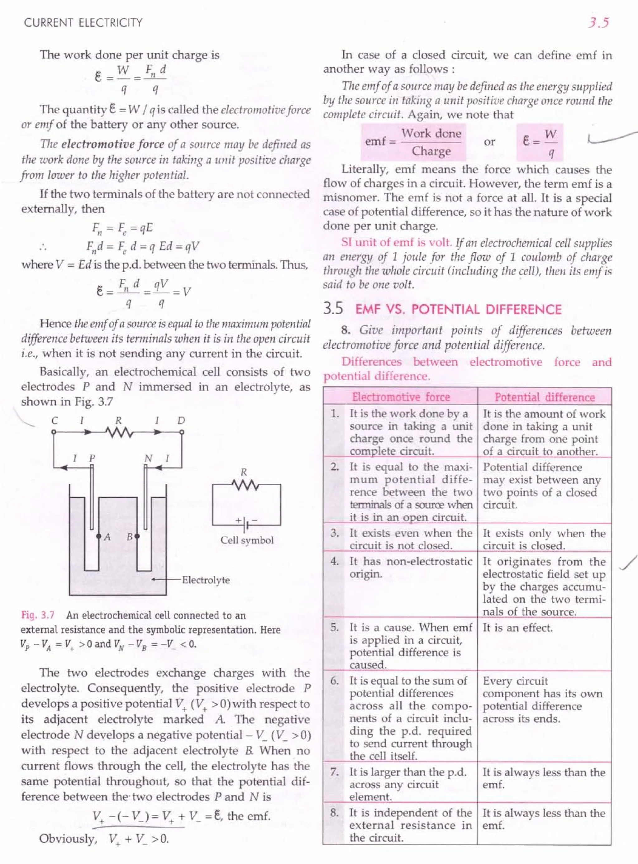
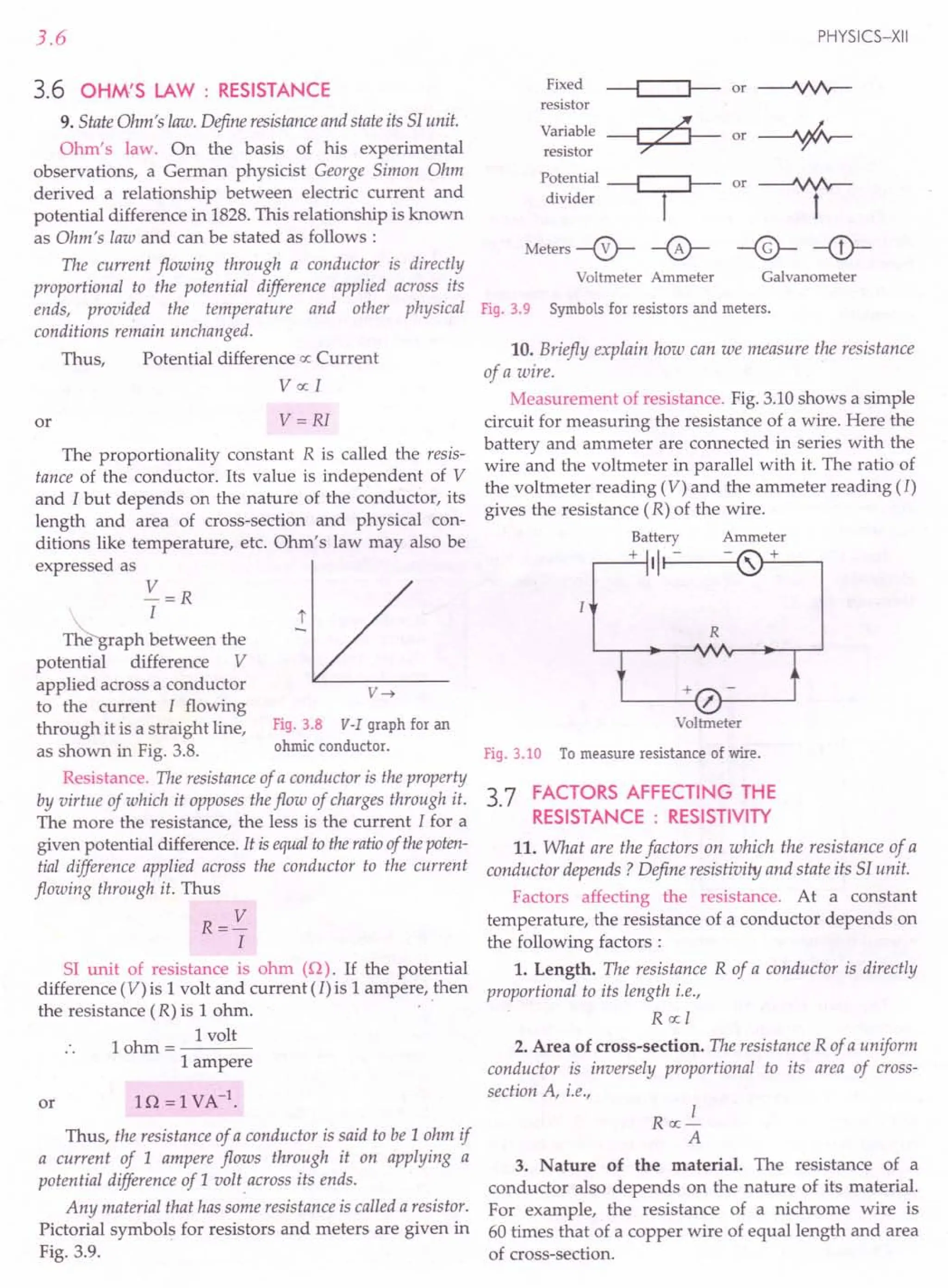
![CURRENT ELECTRICITY
Combining the above factors, we get
I I
R ex: - or R =p -
A A
where p is the constant of proportionality called resistivittj
or specific resistance of the material of the conductor. It
depends on the nature of the material of the conductor
and on the physical conditions like temperature and
pressure but it is independent of its size or shape.
Resistivity or specific resistance. If in the above
equation, we take
I = 1unit and A = 1square unit
then R = p
Thus, the resistivity or specific resistance of a material
may be defined as the resistance of a conductor of that
material, having unit length and unit area of cross-section.
Or, it is the resistance offered by the unit cube of the material
of a conductor.
51 unit of resistivity. We can write
RxA
p=--
I
51
. f ohm x metre/
unit 0 p = ------
metre
= ohm meter (Q m)
Thus, the 51 unit of resistivity is ohm metre (Q m).
3.8 CURRENT DENSITY, CONDUCTANCE
AND CONDUCTIVITY
12. Define the terms current density, conductance
and conductivity. Write their 51 units. Express Ohm's
law in vector form.
Current density. The current density at any point
inside a conductor is defined as the amount of chargeflowing
per second through a unit areaheld normal to the direction of
the flow of charge at that point. It is a vector quantity
having the same direction as that of the motion of the
positive charge. It is a characteristic property of any
->
point inside the conductor and is denoted by j .
As shown in Fig. 3.11(a), if a current 1is flowing
uniformly and normally through an area of cross-
section A of a conductor, then the magnitude of current
density at any point of this cross-section will be
. q / t I
t=r+=r:
A A
If the area A is not perpendicular to the direction of
current and normal to this area makes angle 8 with the
direction of current as shown in Fig. 3.11(b), then the
component of A normal to the direction of current
flow will be
~=Acos8
3.7
Area =A
--+
A
(a)
--+
A
(b)
Fig. 3.11 Current density.
Current density,
. I I
}=-=
An A cos 8
or
-> ->
I = jA cos 8 = j . A
This equation again shows that electric current,
being scalar product of two vectors, is a scalar quantity.
The 51 unit of current density is ampere per square
metre (Am -2) and its dimensions are [AL-2].
NOT E The current I through a particular surface 5 in
->
a conductor is the flux of j through that surface and is
given by the surface integral
I=ff.as
5
->
where dS is a small element of the given surface area.
Conductance. The conductance of a conductor is the
ease with which electric chargesflow through it. It is equal to
the reciprocal of its resistance and is denoted by G.
Thus,
or
1
Conductance = ----
Resistance
1
G=-
R
The 51 unit of conductance is ohm-lor mho or
siemens (S)
Conductivity. The reciprocal of the resistivity of a
material is called its conductivity and is denoted by 0.
Thus,
C d
.. 1
on uctivity = ----
Resistivity
1
or 0 =-
p
The 51unit of conductivity is ohm -1 m -1 or mho m-1
or Sm -1.
Vector form of Ohm's Law. If Eis the -nagnitude of
electric field in a conductor of lengti I, then the
potential difference across its ends is
V= EI](https://image.slidesharecdn.com/slaroraclass12thphysicsbyrockytrickster-250318042948-c8b51a5a/75/SL-ARORA-CLASS-12TH-PHYSICS-BY-ROCKY-TRICKSTER-pdf-192-2048.jpg)
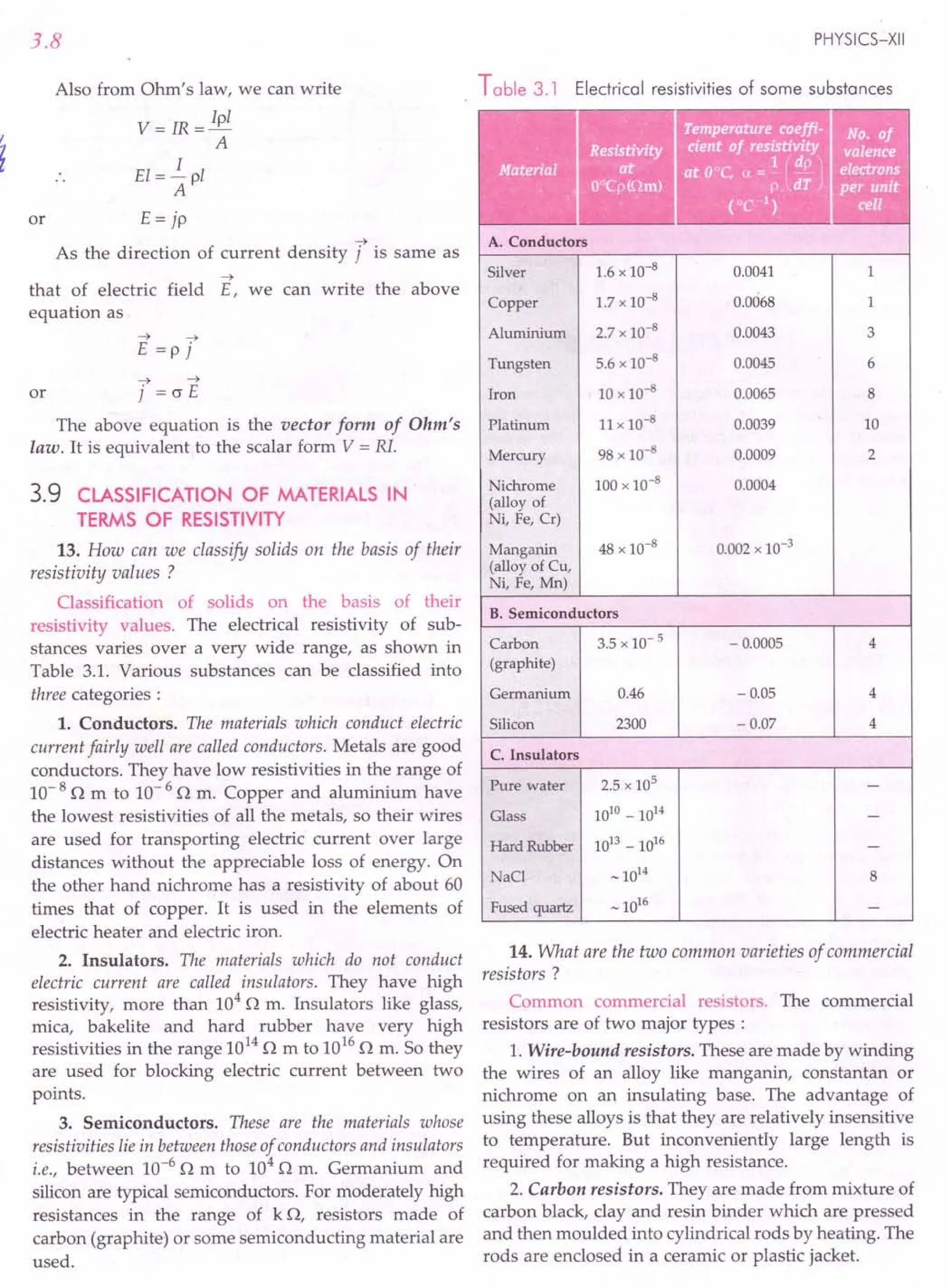
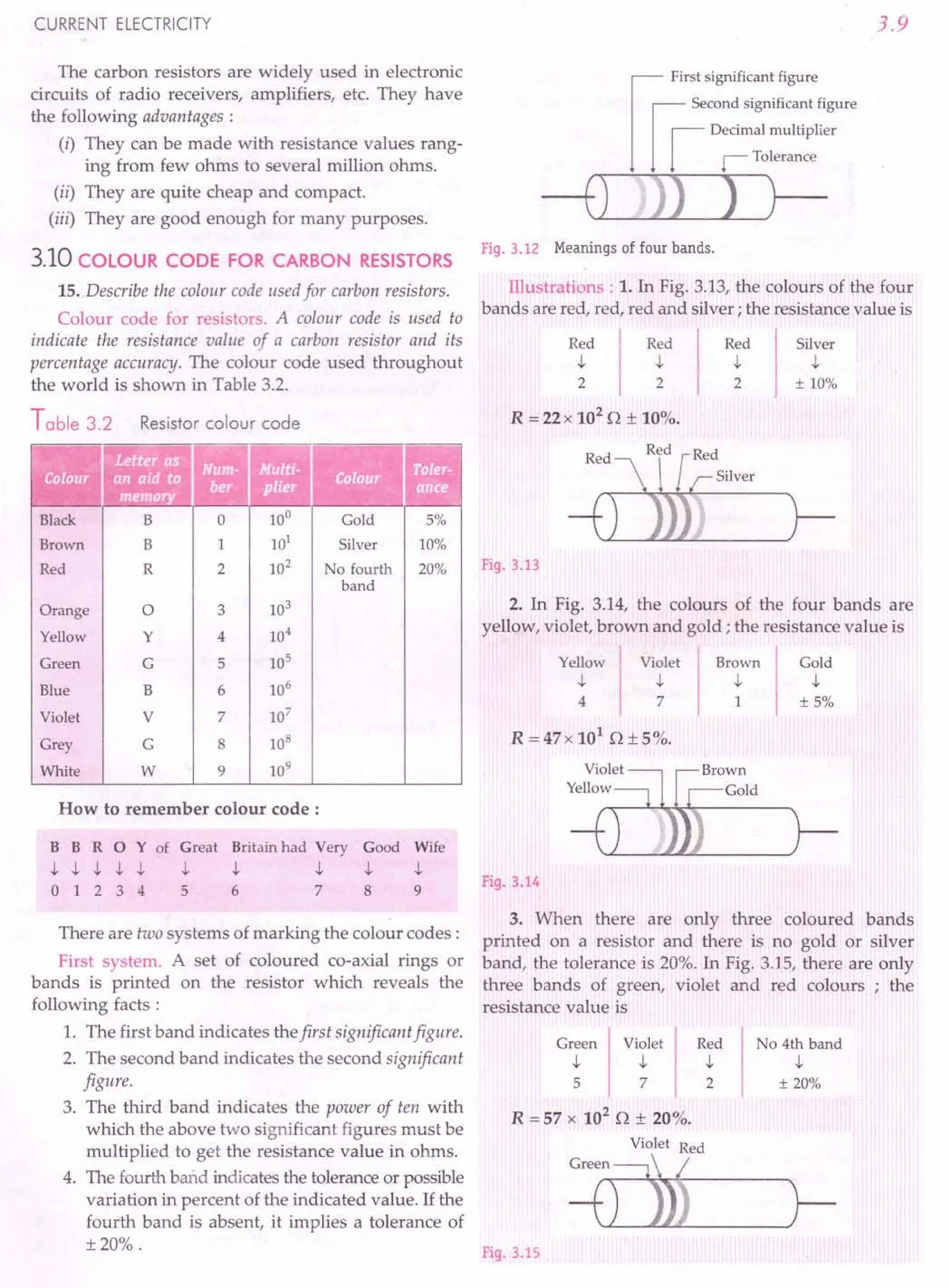
![3.10
Second System :
1. The colour of the body gives the first significant
figure.
Fig. 3.16
2. The colour of the end gives the second signi-
ficant figure.
3. The colour of the dot gives the number of zeroes
to be placed after the second figure.
4. The colour of the ring gives the tolerance or
percent accuracy of the indicated value.
Illustration. Suppose for a given resistor, the body
colour is yellow, end colour is violet, dot colour is
orange and the ring colour is silver.
Body End I Dot Ring
Yei
ow
Vi~let I Orr
ge
I Silr
er
4 7' 3 ± 10%
:. R = 47 x 103
0 ± 10% = 47 kO ± 10%.
Conductance, ConductiviW, I- - .
•• - ..
.... . •
Formulae Used
V
1. Ohm's law, R = - or V = IR
I
2. Resistance of a uniform conductor, R = p ~
A
RA
3. Resistivity or specific resistance, p = -[-
1
4. Conductance = -
R
C d
.. 1
5. on uctivity = ----
Resistivity
. Current
6. Current density = ---
Area
1 [
or (J=- =-
P RA
. I
or ] =-
A
7. Colour code of carbon resistors. Refer to Table 3.2.
Units Used
Potential difference V is in volt (V), current I in
ampere (A), resistance R in ohm (0), resistivity p
in Om, conductance in ohm -lor mho or siemens
(S), conductivity in 0 -1m -lor Sm -1 and current
density j in Am -2.
PHYSICS-XII
Example 9. In a discharge tube, the number of hydrogen
ions (i.e., protons) drifting across a cross-section per second
is 1.0 x 10¹⁸, while the number of electrons drifting in the
opposite direction across another cross-section is 2.7 x 10¹⁸
per second. If the supply voltage is 230 V, what is the
effective resistance of the tube? [NCERT]
Solution. The current carried by a negatively charged
electron is equivalent to the current carried by a proton
in the opposite direction, therefore, total current in the
direction of protons is
I = Total charge flowing per second =(ne + np) e
= [2.7 x 10¹⁸ + 1.0 x 1018] x 1.6 x 10-19
= 3.7 x 1.6 x 10-1
=0.592 A
Effective resistance,
R = V = 230 0 =388.50 =- 3.9 x 10²
O.
I 0.592
Example 10. A 10 V battery of negligible internal
resistance is connected across a 200 V battery and a resis-
tance of 380 as shown in the figure. Find the value of the
current in circuit. [CBSE D13]
10V
~~
200 V
Solution. 1= V = 200 -10 = 5 A
R 38
Example 11. A copper wire of radius 0.1 mm and
resistance 1k 0 is connected across a power supply of 20 V.
(i) How many electrons are transferred per second between
the supply and the wire at one end? (ii) Write down the
current density in the wire.
Solution. Here r =0.1 mm =0.1 x 10⁻³ m,
R =1 kO =103
0, V =20 V
(i) Current, 1= V = 20
3
= 0.02 A
R 10
No. of electrons,
q It
n=-=-
e e
0.02 x 1 17
---Cl~9 = 1.25 x 10 .
1.6 x 10-
(ii) Current density,
. I I 0.02
] = A = 1tr2 = 3.14 x (0.1 x 10-3)2
= 6.37 x 10⁵ Am -2.](https://image.slidesharecdn.com/slaroraclass12thphysicsbyrockytrickster-250318042948-c8b51a5a/75/SL-ARORA-CLASS-12TH-PHYSICS-BY-ROCKY-TRICKSTER-pdf-195-2048.jpg)
![CURRENT ELECTRICITY
Example 12. Current flows through a constricted con-
ductor, as shown in Fig. 3.17. The diameter 01 =2.0 mm
and the current density to the left of the constriction is
7 = 1.27 x 10⁶
Am-2. (i) What current flows into the
constriction ? (ii) If the current density is doubled as it
emerges from the right side of the constriction, what is
diameter 02 ?
,
,
, r ,
I
II
, , ,
, , ,
, ,
, , ,
,
,
,
Fig. 3.17
Solution. Here 01 = 2.0 mm, 71 = 1.27 x 10⁶ Am -2,
72 =2 71
(i) Current flowing into the constriction,
II = 71 A= i, x n( ~1 J
= 1.27 x 106 x 3.14 x (1 x 10-3)2 = 3.987 A
(ii) For a steady flow of current,
11=12
71~ =72x Az
71 x n ( ~1 r= 72 x n ( ~2 r
71 x n( ~1 r=2jl x n( ~2 r r. 72 =271]
1
02 = .fi 01 = 0.707 01
or
or
or
or
= 0.707 x 2.0 mm = 1.414 mm.
Example 13. A current of 2 mA is passed through a
colour coded carbon resistor with first, second and third
rings of yellow, green and orange colours. What is the
voltage drop across the resistor?
Solution.
Yellow
t
4
Orange
t
3
Green
t
5
R = 45 x 103
D
Given 1=2 mA = 2 x 10⁻³
A
V = RI = 45 x 103
x 2 x 10-3
V = 90 V.
Example 14. An arc lamp operates at 80 V, 10 A Suggest
a method to use it with a 240 V d.c. source. Calculate the
value of the electric component required for this purpose.
[CBSE F 94]
3.11
Solution. Resistance of the arc lamp is
R= V =80 =8D
I 10
In order to use arc lamp with a source of 240 V, a
resistance R' should be connected in series with it so
that current through the circuit does not exceed 10 A.
Then
I(R+R')=V or 1O(8+R')=240
or R' = 24 - 8 = 16 D.
Example 15. Calculate the resistivity vf a material of a
wire 10 m long, 0.4 mm in diameter and having a resistance
of2.0 D. [Haryana 02]
Solution. Here I= 10 m, r = 0.2 mm = 0.2 x 10- 3 m,
R=2D
Resistivity,
RA Rxnr2
P==-I-= I
= 2 x 3.14 x (0.2 x 10- 3)2 = 2.513 x 10⁻⁸Dm.
10
Example 16. The external diameter of a 5 metre long
hollow tube is 10 emand the thickness of its wall is 5 mm If
the specific resistance of copper be 1.7 x 10- 5 ohm-metre,
then determine its resistance.
Solution. The cross-sectional area of the tube is
2 2
A=n(r2-r1)
=3.14 x [(5 x 10⁻²)2 -(4.5 x 10⁻²)2]
= 14.9x10⁻⁴
m2
Also, P = 1.7 x 10⁻⁸
Dm, I = 5 m
.. Resistance,
R- i_1.7x10-8x5
- P A - 14.9 x 10-4
= 5.7 x 10⁻⁵
D.
Example 17. Find the resistivity of a conductor in which a
current density of 2.5 Am-2
is found to exist, when an
electricfield of15 Vm- 1 is applied on it. [ISCE 98]
Solution. Here 7 =2.5 Am-2, E =15 Vm-1
RA V A
Resistivity, P = - = - . -
I I I
= VII =~=~=6Dm.
l/ A 7 2.5
Example 18. Calculate the electrical conductivity of the
material of a conductor of length 3 m, area of cross-section
0.02 m~ having a resistance of2 D.
Solution. Here I= 3 m, R = 2 D,
A =0.02 mm ' =0.02 x 10- 6 m2](https://image.slidesharecdn.com/slaroraclass12thphysicsbyrockytrickster-250318042948-c8b51a5a/75/SL-ARORA-CLASS-12TH-PHYSICS-BY-ROCKY-TRICKSTER-pdf-196-2048.jpg)
![3.12
Electrical conductivity = 1
Resistivity
1 I 3
0=-=-=---------0-
P RA 2 x 0.02 x 10-6
= 75 x 106 0-lm-1.
Example 19. A wire of resistance 4 0 is used to wind a coil or
of radius 7 em The wire has a diameter of 1.4 mm and the
specific resistance of its material is 2 x 10- 7 Om Find the
number of turns in the coil.
Solution. Let n be the number of turns in the coil.
Then total length of wire used
=21t Rx n =21tx7x 10-2 x n metre
Total resistance,
or
1
R=p-
A
or
n= 70.
Example 20. A wire of 10 ohm resistance is stretched to
thrice its original length. What will be its (i) new resistivity,
and (ii) new resistance? [CBSE D 98C]
Solution. (i) Resistivity p remains unchanged
because it is the property of the material of the wire.
(ii) In both cases, volume of wire is same. So
V= A'l' =AI
A' I I 1
or -=-=- [.: l'=1+21=3ij
A l' 31 3
l'
R' P A' l' A 3 3
-=--=-x -=-x -=9
R I I A' 1 1
p-
A
Hence R' =9R =9 x 10 =900.
Example 21. A wire has a resistance of16 O. It is melted
and drawn into a wire of half its length. Calculate the
resistance of the new wire. What is the percentage change in
its resistance ?
Solution. In both cases, volume of the wire is same.
V= A'l' =AI
A' I I 2
A=r=ll=l
2
or
or
l'
R' P A' l' All 1
-=--=-x -=-x -=-
R IIA'224
p-
A
R' = .! R =.! x 16 = 40.
4 4
Change in resistance
R - R' 12
= -- x 100 = - x 100 = 75%.
R 16
PHYSICS-XII
Example 22. The resistance of a wire is R ohm. What will
be its new resistance if it is stretched to n times its original
length?
Solution. In both cases, volume of the wire is same.
V= Al = A'l'
A l'
-=-=n
A' I
[.: I' = nil
or
l'
R' P =: l' A 2
-=-LL=-.-=n.n=n
R I I A'
p-
A
R'=n2
R.
Example 23. A cylindrical wire is stretched to increase its
length by 10%. Calculate the percentage increase in
resistance.
or
Solution. New length, l' = 1+ 10% of I
=1+0.11=1.11
£. = 1.1
I
AI=A'l'
A l'
A' I
~=£.x~=(£.)2 =(1.1l=1.21
R I A' I
or
The percentage increase in resistance,
R' - R (R')
-R- x 100 = R-1 x 100 =(1.21-1)x 100 = 21%.
Example 24. Two wires A and B of equal mass and of the
same metal are taken. The diameter of the wire A is half the
diameter of wire B. If the resistance of wire A is 240,
calculate the resistance of wire B.
Solution. Mass of wire = volume x density
= area of cross - section x lengthx density
2 2
m = 1trA IA d = 7trBIBd
or !JL = (rA J2 =(~)2 1
IA rB 1 4
:~ 0: ':~: 0;~,(:. r0~'G)'
01~
1trA
1 1
or RB = 16 RA = 16 x 240 = 1.5 O.
Example 25. A pieceof silver has aresistance of 10. What
will be the resistance of a constantan wire of one-third length
and one-half diameter, if the specific resistance of constantan
is 30 times that of silver ?](https://image.slidesharecdn.com/slaroraclass12thphysicsbyrockytrickster-250318042948-c8b51a5a/75/SL-ARORA-CLASS-12TH-PHYSICS-BY-ROCKY-TRICKSTER-pdf-197-2048.jpg)
![CURRENT. ELECTRICITY
Solution. For silver,
R=4pI=10n
n d2
For constantan,
1
4 /l' 4 x 30 P x -
R'=-P-= 3
nd/
2
n(~J
40 x 4p 1
= 2 = 40 R = 40 x 1= 40 n.
ttd
Example 26. On applying the same potential difference
between the ends of wires of iron and copper of the same
length, the same current flows in them. Compare their radii.
Specific resistances of iron and copper are respectively
1.0 x 10- 7 and 1.6 x 10- 8 nm Can their current-densities
be made equal by taking appropriate radii ?
Solution. On applying same potential difference,
same current flows in the two wires. Hence the
resistances of the two wires should be equal.
1 1
But R=p-=p-
A nr2
For the two wires of same length 1, we have
1 1
Rl =PI-2 and ~ =P2 -2'
rt r1 rt r2
As Rl=~
PI P2
1=rf or
riron = Piron = 1.0 x 10- 7 = 2.5.
~opper Pcopper 1.6 x 10- 8
No, current densities cannot be equal because they
depend on nature of the metals.
cproblems ForPractice
1. A voltage of 30 V is applied across a colour coded
carbon resistor with first, second and third rings of
blue, black and yellow colours. What is the current
flowing through the resistor? [CBSE D 05]
(Ans. 0.5 x 10⁻⁴A)
2. A potential difference of 10 V is applied across a
conductor of resistance 1k n. Find the number of
electrons flowing through the conductor in
5 minutes. (Ans. 1.875x 10¹⁹
)
3. What length of a copper wire of cross-sectional area
0.01mm 2would be required to obtain a resistance
of 1k n ? Resistivity of copper = 1.7x1O-8nm.
(Ans. 588.2m)
3.13
4. A metal wire of specific resistance 64 x 1O-8
n m
and length 1.98m has a resistance of 7 n. Find its
radius. (Ans. 2.4 x 10⁻⁴m)
5. Calculate the resistance of a 2 m long nichrome wire
of radius 0.321 mm. Resistivity of nichrome is
15x 10-6
n m. If a potential difference of 10 V is
applied across this wire, what will be the current in
the wire? (Ans. 9.26n, 1.08A)
6. An electron beam has an aperture of 1.0mm 2. A
total of 6 x 10¹⁶
electrons flow through any
perpendicular cross-section per second. Calculate
(i) the current and (ii) the current density in the
electron beam.
[Ans. (i) 9.6x 10⁻³A (ii) 9.6x 10³Am-2]
7. Calculate the electric field in a copper wire of
cross-sectionalarea 2.0 mm2
carrying a current of
1 A.The resistivity of copper = 1.7 x 10⁻⁸
nm.
(Ans. 0.85x 10⁻² Vm-1)
8. A given copper wire is stretched to reduce its
diameter to half its previous value. What would be
its new resistance? [CBSE D 92C]
(Ans. R' = 16 R)
9. What will be the change in resistance of a
constantan wire when its radius is made half and
length reduced to one-fourth of its original length ?
(Ans. No change)
10. A wire of resistance 5n is uniformly stretched until
its new length becomes 4 times the original length.
Find its new resistance. (Ans.80n)
11. A metallic wire of length 1 m is stretched to double
its length. Calculate the ratio of its initial and final
resistances assuming that there is no change in its
density on stretching. [CBSE D 94]
(Ans.1 : 4)
12. A wire of certain radius is stretched so that its
radius decreases by a factor n Calculate its new
resistance. (Ans. n4
R)
13. A wire 1 m long and 0.13 mm in diameter has a
resistance of 4.2n. Calculate the resistance of
another wire of the same material whose length is
1.5m and diameter 0.155mm. (Ans.4.4n)
14. A rheostat has 100turns of a wire of radius 0.4mm
having resistivity 4.2x10⁻⁷
nm. The diameter of
each turn is 3 cm. What is the maximum value of
resistance that it can introduce? (Ans. 7.875n)
15. Given that resistivity of copper is 1.68x 10- 8 nm.
Calculate the amount of copper required to draw a
wire 10km longhaving resistanceof10n. Thedensity
of copper is 8.9x10³
kgm-3. (Ans. 1495.2kg)](https://image.slidesharecdn.com/slaroraclass12thphysicsbyrockytrickster-250318042948-c8b51a5a/75/SL-ARORA-CLASS-12TH-PHYSICS-BY-ROCKY-TRICKSTER-pdf-198-2048.jpg)
![3.14
16. The size of a carbon block is 1.0em x1.0cm x50 cm.
Find its resistance (i) between the opposite
square faces (ii) between the opposite rectangular
faces of the block. The resistivity of carbon is
3.5x10⁻⁵
0 cm. (Ans. 0.1750, 7.0 x 10- 5 0)
17. Two wires A and B of the same material have their
lengths in the ratio 1 : 5 and diameters in the ratio
3 : 2. If the resistance of the wire B is 1800, find the
resistance of the wire A. (Ans. 160)
18. A uniform wire is cut into four segments. Each
segment is twice as long as the earlier segment. If
the shortest segment has a resistance of 4 0, find the
resistance of the original wire. (Ans. 60 0)
19. Calculate the conductance and conductivity of a
wire of resistance 0.010, area of cross-section
10-4m2 and length 0.1 m. [Haryana 2000]
(Ans. 100 S, 105
Sm-1)
HINTS
1. R = 60 x 104
0, V = 30 V
V 30 4
I = - = 4 = 0.5 x10 A.
R 60 x 10
2. I = V = 10V = ~ = 10-2A
R UO 10000
_ 3. _ ~ _ 10-
2
x5 x60 _ 1 875 1019
n - e - e - 1.6x 10 19 -. x
4 A R
-pl_~
. s -A-n';
:. y2 =~ = 64x10-
8
x1.98x7 = 5.76x1O-8m2
nR 22x7
or y = 2.4 x 10⁻⁴
m.
I V
5. Use R=p~and I=-.
nr R
q ne 6 x1(y.6 x16 x10-19
6. (i) I=-=-=------
t t 1
= 9.6xl0-3
A.
(ii) Current density,
.-i -9.6x 10-
3
_ 9 6 103Am-2
] - A - 1.0x10⁻⁶ - . x .
V IR Ipl Ip 1x1.7x10-8
7. E=-=-=-=-=---..".-
I I IA A 20 x10-6
=0.85 xl0-2
Vm-1.
8. When the diameter of the wire is reduced to its half
value, area of cross-section becomes one-fourth and
the length increases to four times the original
length. .
, I' 41 I
R =p A,=P'-1-=16p A =16R.
-A
4
PHYSICS-XII
I I
9. R=P-=P-2
A 1tY
R' = p 'l/ 4 = p _1_ = R
1t (Y /2)2 ny
2
I .
10. R=p- =50
A
R'=p ~ = 16p ~ = 16 R= 16 x5= 800.
A/4 A
I
11. R=p-
A
R' = p ~ = 4p ~ = 4 R
A/2 A
.. R: R' =1: 4.
12. V = A' I'= Al
or V = 1t (.;;Y I' = 1t y2 I or I'= ~ I
R' I ' n
2
I 4 I 4 R
=P--2 =p 2 =np-=n .
1tY' 1t (y / n) nr2
13. Rz = 1) [ t][~r
= 4.2[1.5] [ 0.13 x 10- 3 ]2 = 4.4O.
1 0.155xlO-3
14. Length of the wire used, I = lOOnD
I 100nD lOOpD
R=p ~ =P'-;r=-,;-
100 x 4.2 x10-7
x3 x10-2
-----"3 "2-- = 7.875O.
(O.4x10 )
I
15. As R=p-
A
pi 1.68x 10-8
x10xl03
5 2
A=-= =1.68xl0- m
R 10
Mass of copper required,
m = Volume x density = Al x density
= 1.68x 10-5 x 10x 103 x 8.9 x 103
= 1495.2 kg.
(i) R = ~ = 3.5x10-
5
x50x10-
2
= 0.175o.
PALO x10-2 x1.0x10-2
(ii) R = ~ = 3.5x10-
5
x1.0x10-
2
= 7.0xl0-50.
PALO x10-2x50x10-2
IA
RA = P ~ = I
A (.'!JL]2 =.! x (~)2= ~
R8 _18_ 18 dA 5 3 45
p nd~ /4
4 4
RA = 45 R8 = 45 xI80=160.
16.
17.](https://image.slidesharecdn.com/slaroraclass12thphysicsbyrockytrickster-250318042948-c8b51a5a/75/SL-ARORA-CLASS-12TH-PHYSICS-BY-ROCKY-TRICKSTER-pdf-199-2048.jpg)
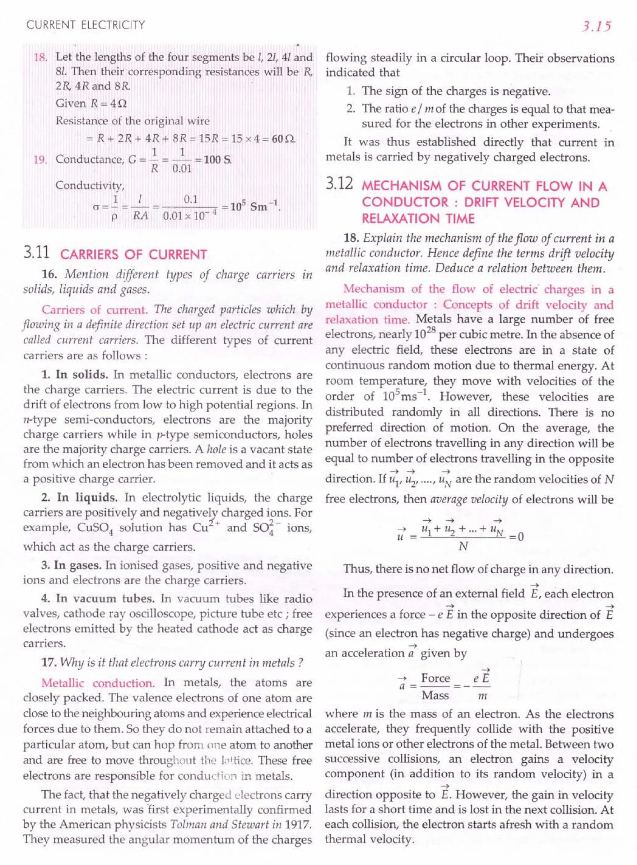
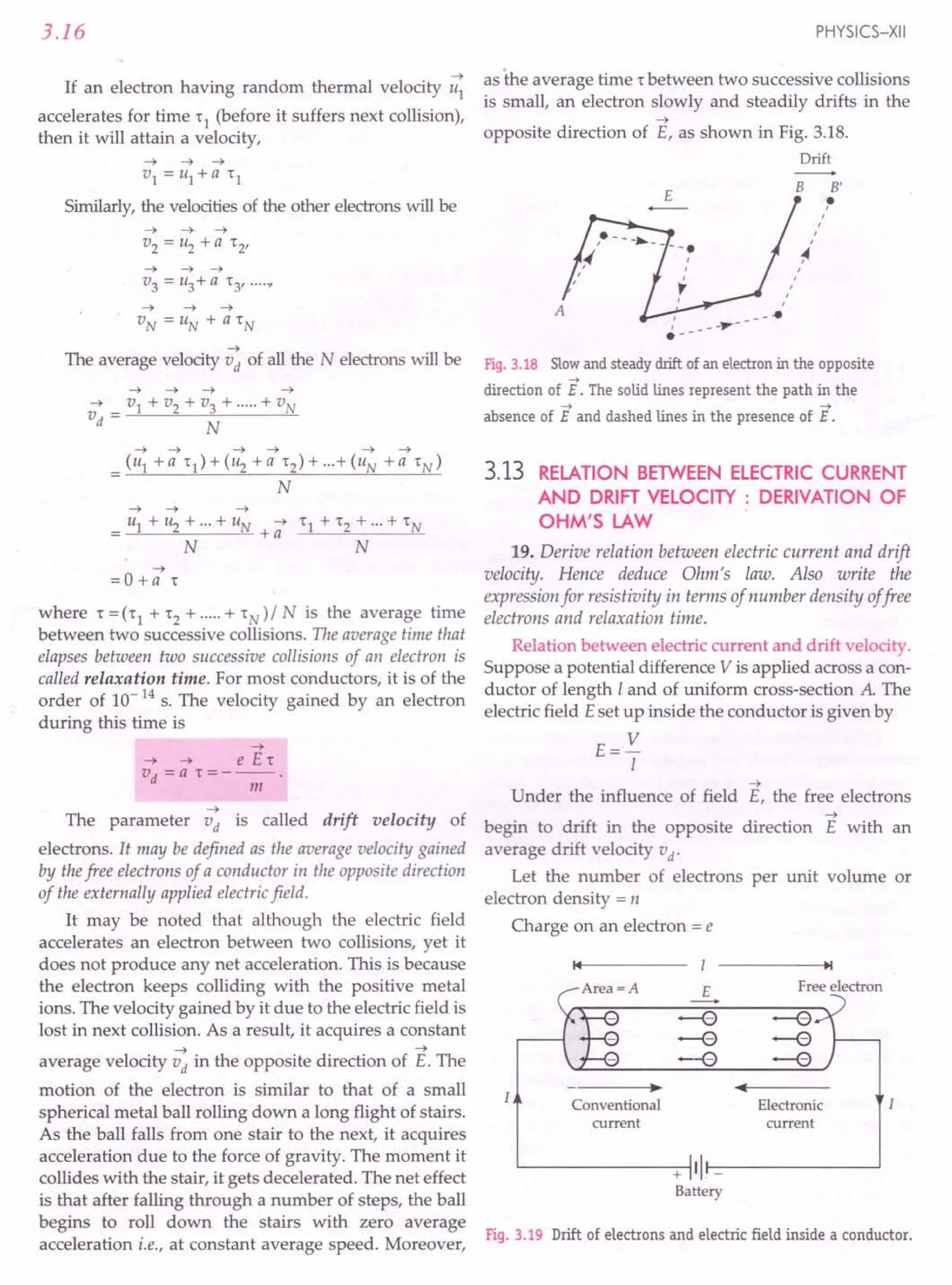
![CURRENT ELECTRICITY
Number of electrons in length I of the conductor
= n x volume of the conductor = n Al
Total charge contained in length I of the conductor is
q= en Al
All the electrons which enter the conductor at the
right end will pass through the conductor at the left
end in time,
:. Current,
distance I
t= =-
velocity "«
I=:J. = enAI
t 1/ vd
I=enAvd
or
This equation relates the current I with the drift
velocity vd
.
The current density' j , is given by
. I
] = - =envd
A
7 ~
In vector form ] = en vd
The above equation is valid for both positive and
negative values of q.
Deduction of Ohm's law. When a potential
difference V is applied across a conductor of length I,
the drift velocity in terms of V is given by
eE't eV't
vd=-=-
m mi
If the area of cross-section of the conductor is A and
the number of electrons per unit volume or the electron
density of the conductor is n, then the current through
the conductor will be
eV't
I=enAvd
=enA.-
mi
or
V
I
mi
-2--'
ne 'tA
At a fixed temperature, the quantities m, I, n, e, t and
A, all have constant values for a given conductor.
Therefore,
V
- = a constant, R
I
This proves Ohm's law for a conductor and here
R=~
ni'tA
is the resistance of the conductor.
Resistivity in terms of electron density and relaxation
time. The resistance R of a conductor of length I, area of
cross-section A and resistivity p is given by
I
R=p-
A
3.17
R=~
ni'tA
where r is the relaxation time. Comparing the above
two equations, we get
But
m
P=ne2't
Obviously, p is independent of the dimensions of
the conductor but depends on its two parameters:
1. Number of free electrons per unit volume or
electron density of the conductor.
2. The relaxation time r, the average time between
two successive collisions of an electron.
~ ~
20. Write relation between quantitiesj r 0 and E.
~ ~
Relation between j , 0 and E . For an electron,
q=-e
~
~ e E«
and vd =---
m
~
7 ~ ( e E 't) ne
2
't ~
] =nqvd =n(-e) ----;;;- =-;;;- E
ne2
't 1 ..
But -- = - = 0, conductivity of the conductor
m p
~ ~ ~ ~
j = 0 E or E =p j
This is Ohm's law in terms of vector quantities like
~ ~
current density j and electric field E.
21. What causes resistance in a conductor?
Cause of resistance. Collisions are the basic cause of
resistance. When a potential difference is applied
across a conductor, its free electrons get accelerated.
On their way, they frequently collide with the positive
metal ions i.e., their motion is opposed and this
opposition to the flow of electrons is called resistance.
Larger the number of collisions per second, smaller is
the relaxation time r, and larger will be the resistivity
(p = m/ ne2 t).
The number of collisions that the electrons make with
the atoms/ions depends on the arrangement of atoms
or ions in a conductor. So the resistancedependson thenature
of the material (copper, silver, etc.) of the conductor.
The resistance of a conductor depends on its length. A
long wire offers more resistance than short wire
because there will be more collisions in the longer wire.
The resistance of conductor depends on its area of cross-
section. A thick wire offers less resistance than a thin
wire because in a thick wire, more area of cross-section
is available for the flow of electrons.](https://image.slidesharecdn.com/slaroraclass12thphysicsbyrockytrickster-250318042948-c8b51a5a/75/SL-ARORA-CLASS-12TH-PHYSICS-BY-ROCKY-TRICKSTER-pdf-202-2048.jpg)
![3.18
22. Alloys of metals have greater resistivity than their
constituent metals. Why ?
High resistivity of nichrome. In an alloy, e.g.,
nichrome (Ni - Cr alloy), Ni2
+ and Cr3
+ ions have
different charge and size. They occupy random locations
relative to each other, though their ionic sites form a
regular crystalline lattice. An electron, therefore, passes
through a very random medium and is very frequently
deflected. So there is a small relaxation time and hence
large resistivity. In general, alloys have more resistivity
than that of their constituent metals.
23. Explain the cause of instantaneous current in an
electric circuit.
Cause of instantaneous current. Although the drift
speed of electrons is very small, typically 1 mm/s, yet
an electric bulb lights up as soon as we turn the switch
on. This is because electrons are present everywhere in
an electric circuit. When a potential difference is
applied to the circuit, an electric field is set up through-
out the circuit, almost with the speed of light. Electrons
in every part of the circuit begin to drift under the
influence of this electric field and a current begins to
flow in the circuit almost immediately.
The above situation is analogous to the flow of
water in a long pipe. As soon as the pressure is applied
at one end of the water filled pipe, a pressure wave is
transmitted along the pipe with a speed of about
1400 ms - 1. When this wave reaches the other end,
water starts flowing out. But water inside pipe moves
forward with a much smaller speed.
Formulae Used
1. Current in terms of drift velocity (vd) is I = en A vd
2. Current density, j = envd
3. No. of atoms in one gram atomic mass of an
element, N = Avogadro's number = 6.023 x 10²³
.
4. In terms of relaxation time r,
R=~ and p=~
ne2
'tA ne2
't
5. Relation between current density and electric field,
j=crE or E=pj
Units Used
Drift velocity vd is in ms -1, free-electron density in
m -3, cross-sectional area A in m 2, current density
j in Am - 2, all resistances in n.
Constants Used
e = 1.6 x 10⁻¹⁹
C and NA = 6.023 x 10²³
mol-1
.
PHYSICS-XII
Example 27. Assuming that there is one free electron per
atom in copper, determine the number of free electrons in
1 metre3
volume of copper. Density of copper is
8.9 x 10³
kgm-3
and atomic weight 63.5. (Avogadro's
number, N = 6.02 x 1026
per kg-atom).
Solution. If the atomic weight of a material is Mkg
and the density is d kgm -3, then the volume of its
1 kg-atom will be (Mid) m3.
According to Avogadro's hypothesis, there are
6.02 x 1026
atoms in 1 kg-atom of the material. This
number is called Avogadro's number (N). Thus
Number of atoms in (Mid) m3 volume of a material
=N
.. Number of atoms in 1 m3 volume
N dx N
=--=--
Mid M
Assuming 1 free electron per atom in copper, the
number of free electrons in 1 m3 volume of copper will be
dx N
n=--
M
Now d =8.9 x 10³ kg m-3, N =6.02 x 1026
,
M=63.5 kg
8.9 x 103
x 6.02 x 1026
28 3
n = = 8.4 x 10 m -
63.5
Example 28. A copper wire has a resistanceof10 n and an
area of cross-section 1 m~. A potential difference of 10 V
exists across the wire. Calculate the drift speed of electrons if
the number of electrons per cubic metre in copper is
8 x 1028
electrons. [CBSE D 96]
Solution. Here R= lOn, A=lmm2
=10-6
m2
,
V = 10 V, n =8 x 1028
electrons I m3
Now I = en A vd
V
-=enAvd
R
V 10
v - -- - ------::-:0:-------::-;;:----,--
d - enAR - 1.6 x 10-19 x 8 x 1028 x 10-6 x 10
= 0.078 x 10⁻³ms-1 = 0.078 mm S-l.
Example 29. (a) Estimate the average drift speed of
conduction electrons in a copper wire of cross-sectional area
1.0 x 10⁻⁷
~, carrying a current of1.5 A Assume that each
copper atom contributes roughly one conduction electron.
The density of copper is 9.0 x 10³
kg m-3
, and its atomic
mass is 63.5 u. TakeAvogadro's number =6.0 x 10²³ mol-I.
(b) Compare the drift speed obtained above with
(i) thermal speeds of copper atoms at ordinary temperatures,
(ii) speeds of electrons carrying the current and (iii) speed of
propagation of electric field along the conductor which
causes the drift motion. [NCERT]
or](https://image.slidesharecdn.com/slaroraclass12thphysicsbyrockytrickster-250318042948-c8b51a5a/75/SL-ARORA-CLASS-12TH-PHYSICS-BY-ROCKY-TRICKSTER-pdf-203-2048.jpg)
![CURRENT ELECTRICITY
Solution. Mass of 1 m3 of Cu
= 9.0 x 10³ kg =9 x 10⁶
g
Since Avogadro's number is 6.0 x 10²³ and atomic
mass of Cu is 63.5 u, therefore, 63.5 g of Cu contains
6.0 x 10²³ atoms.
So 9 x 10⁶
g of Cu contains
60 x 1023
. x 9 x 10⁶ atoms = 8.2 1028 atoms
63.5
Number of conduction electrons,
n = number of Cu atoms =8.5 x 1028
Now 1=1.5 A, A=10-7
m2
, e=1.6xlO-19
C
I 1.5
v - - - ----::-;,-----:::.,,-----:=-
d - enA - 1.6 x 10-19 x 8.5 x 1028x 10-7
15 = 11 10-3 -1
• x ms.
16 x 85 x 10
(b) (i) At any temperature T, the thermal speed of a
copper atom of mass M is given by
_tkBT
vrms - M
But ordinary temperature, T "'-300 K,
Boltzmann constant, kB = 1.38 x 10⁻²³JK-I,
Mass of a copper atom,
M _ 63.5
- 6.0 x 10²³ g
63.5 x 10⁻³ k
6.0 x 10²³ g
3 x 1.38 x 10- 23x 300 x 6.0 x 1023
63.5 x 10- 3
= .J117354.33 =342.57 ms-1
From part (a), drift speed of electrons,
vd = 1.1 x 1O-3ms-1
vd (electrons) 1.1 x 10⁻³ 6
---'''------- = = 3.21 x 10- .
vrms
(Cu atoms) 342.57
(ii) The maximum kinetic energy ..! mv~ of electron
2
in copper corresponds to a temperature,
To = 10
5
K
1 2
- mV
F
= kB T
2
or
V
F
= )2kBT = 2 x 1.38 x 10-
23
x 10
5
m 9.1 x 10-31
= 1.74 x 10⁶ ms-1.
vd (electron) = 1.1x 10-
3
"'-10-9.
V
F
(electron) 1.74 x 10⁶
3.19
(iii) An electric field propagates along a conductor
with the speed of an electromagnetic wave i.e.,
3 x 10⁸ ms-1.
vd (electron) 1.1x 10⁻³
speed of propagation of electric field 3 x 10⁸
"'-10-11
•
Example 30. Calculate the electricfield in a copper wire of
cross-sectional area 2.0 m~ carrying a current of1 A The
conductivity of copper =6.25 x 10⁷
Sm-1
.
Solution. Here A =2.0 mm2 =2.0x 1O-6
m2,
I =1 A, o =6.25 x 10⁷
Sm-1
As j =~ =crE
A
E=_1_= 1
Acr 2.0 x 10-6
x 6.25 x 107
= 8 x 10⁻³ Vm-1.
Example 31. A potential difference of100 V is applied to
the ends of a copper wire one metre long. Calculate the
average drift velocity of the electrons. Compare it with the
thermal velocity at 27°C. Given conductivity of copper,
c = 5.81 x 10⁷
~r
1 m-1
and number density of conduction
electrons, n =8.5 x 1028
m-3
. [NCERT]
Solution. Electric field,
E= V =100V =100Vm-1
I 1m
As j=crE=envd
:. Drift speed,
crE 5.81x 107
x 100
v =-=
d e n1.6 x 10-19 x 8.5 x 1028
= 0.43 ms-1
.
kB = 1.38 x 1O-23JK-1,
T = 27 + 273 = 300 K
me = 9.1 x 10⁻³¹ kg
Thermal velocity of electron at 27°C,
3 x 1.38 x 10-23 x 300
9.1x 10⁻³¹
Now,
~ 0.43 = 3.67 x 10⁻⁶•
vrms
1.17 x 10⁵
Example 32. Find the time of relaxation between collision
and free path of electrons in copper at room temperature.
Given resistivity of copper = 1.7 x 10⁻⁸ Om, number density
of electrons in copper = 8.5 x 1028
m-3
, charge on electron
= 1.6 x 10⁻¹⁹ C, mass of electron = 9.1 x 10⁻³¹ kg and drift
velocity offree electrons = 1.6 x 10⁻⁴
ms-1
.](https://image.slidesharecdn.com/slaroraclass12thphysicsbyrockytrickster-250318042948-c8b51a5a/75/SL-ARORA-CLASS-12TH-PHYSICS-BY-ROCKY-TRICKSTER-pdf-204-2048.jpg)
![3.20
Solution. Here p = 1.7 x 10⁻⁸ nm, n = 8.5 x 1028m -3,
e =1.6x 1O-19c, me =9.1x 10⁻³¹ kg, vd =1.6 x 10⁻⁴ ms-l.
m
As resistivity, p = _e_
ne2
1"
:. Relaxation time,
m 9.1 x 10⁻³¹
1" - __ e_ - --------:;;c-;;,-------;;;;-------;;-
- e2 np - (1.6 x 10⁻¹⁹)2 x 8.5 x 1028 x 1.7 x 10-8
= 2.5 x 10⁻¹⁴
s
Mean free path of electron
=vit = 1.6 x 10-4 x 2.5 x 10-14
= 4.0 x 10-l8m.
Example 33. An aluminium wire of diameter 0.24 em is
connected in series to a copper wire of diameter 0.16 em The
wires carry an electric current of 10 ampere. Find
(i) current-density in the aluminium wire (ii) drift velocity
of electrons in the copper wire. Given: Number of electrons
per cubic metre volume of copper =8.4 x 1028.
Solution. (i) Radius of Al wire,
r= 0.24 =0.12 em =0.12 xlO-2m
2
Area of cross-section,
A = 1t? =3.14 x (0.12 x 10-2)2 = 4.5 x 10⁻⁶m2
:. Current density,
.=.i= 10 =2.2x10⁶Am-2.
] A 4.5 x 10⁻⁶
(ii) Area of cross-section of Cu wire is
A = 1tX(0.08 x 10-2)2 =2.0 x 10⁻⁶ m2
Also,
n = 8.4 x 1028m-3
, e =1.6x 10⁻¹⁹
C, I =10 A
I 10
v - -- - ------:;-;::----~_;:_---__,_
.. d - en A - 1.6 x 10-19 x 8.4 x 1028x 2.0 x 10-6
= 3.7 x 10⁻⁴ ms-l.
Example 34. A current of 1.0 ampere isflowing through a
copper wire of length 0.1 metre and cross-section
1.0 x 1O-6~. (i) If the specific resistance of copper be
1.7 x 10⁻⁸ nm calculate the potential difference across the
ends of the wire. (ii) Determine current density in the wire.
(iii) If there be one free electron per atom in copper, then
determine the drift velocit¥ of electrons. Given : density of
copper =8.9x10³kgm-, atomic weight =' 63.5,
N = 6.02 x 1026 per kg-atom.
Solution. Here I=1.0A,1 =0.1 m, A =1.0 x 10⁻⁶m2,
p =l.7x 1O-8nm, d =8.9 x 10³ kg m-3
(i) Resistance of wire is
R=pl 1.7x10⁻⁸xO.1=1.7x10⁻³n
A LOx 10-6
PHYSICS-XII
:. Potential difference,
V = IR = 1.0 x 1.7 x 10-3 = 1.7 x 10⁻³ V.
(ii) Current density,
. = .i = 1.0 = 1.0 x 10⁶ Am -2.
] A 1.0 x 10⁻⁶
(iii) Free-electron density,
d x N 8.9 x 103 x 6.02 x 1026
n =-- =---------
M 63.5
= 8.4 x 1028m-3
:. Drift velocity,
j 1.0 x 10⁶
V = - = -----;r;------::;o
d en 1.6 x 10- 19 x 8.4 x 1028
= 7.4 x 10⁻⁵ ms-l•
~roblems For Practice
1. The free electrons of a copper wire of cross-
sectional area 10-6
m 2 acquire a drift velocity of
10-4m/s when a certain potential difference is
applied across the wire. Find the current flowing in
the wire if the density of free electrons in copper is
8.5 x 1028electrons/m '. (Ans. 1.36 A)
2. Estimate the average drift speed of conduction
electrons in a copper wire of cross-sectional area
2.5 x 10⁻⁷
m 2 carrying a current of 2.7 A. Assume
the density of conduction electrons to be
9x1028m-3
. [CBSE OD 141
(Ans. 0.75 mms ")
3. A current of 1.8 A flows through a wire of cross-
sectional area 0.5 mm 2.Find the current density in
the wire. If the number density of conduction
electrons in the wire is 8.8 x 1028m -3, find the drift
speed of electrons.
(Ans. 3.6 x 10⁶Am -2,2.56 x 10-4ms-l)
4.. The resistivity of copper at room temperature is
1.7 x 1O-80m. If the free electron density of copper
•is 8.4 x 1028m -3, find the relaxation time for the
free electrons of copper. Given me = 9.11 x 10⁻³¹
kg
and e = 1.6 x 10⁻¹⁹
C. (Ans. 2.49 x 1O-14
s)
5. A copper wire of diameter 1.0 mm carries a'current
of 0.2 A. Copper has 8.4 x 1028 atoms per cubic
metre. Find the drift velocity of electrons, assuming
that one charge carrier of 1.6 x 1O-19
C is associated
with each atom of the metal. [ISCE 971
(Ans. 1.895 x 10⁻⁵
rns ")
6. A current of 2 A is flowing through a wire of length
4 m and cross-sectional area 1 mm2. If each cubic
metre of the wire contains 1029free electrons, find
the average time taken by an electron to cross the
. length of the wire. (Ans. 3.2 x 104s)](https://image.slidesharecdn.com/slaroraclass12thphysicsbyrockytrickster-250318042948-c8b51a5a/75/SL-ARORA-CLASS-12TH-PHYSICS-BY-ROCKY-TRICKSTER-pdf-205-2048.jpg)
![CURRENT ELECTRICITY
7. A 10 C of charge flows through a wire in 5 minutes.
The radius of the wire is 1 mm. It contains 5 x 10²²
electrons per centimetre '. Calculate the current
and drift velocity.
(Ans. 3.33 x 10- 2 A, 1.326 x 10- 6 ms-1)
8. A copper wire of diameter 0.16 em is connected in
series to an aluminium wire of diameter 0.25 cm. A
current of 10 A is passed through them. Find
(i) current density in the copp wire (ii) drift
velocity of free electrons in the aluminium wire.
The number of free electrons per unit volume of
aluminium wire is 1029 m - 3.
(Ans. 4.976x10⁶ Am-2, 1.28 x10⁻⁴ms-l)
9. A current of 30 ampere is flowing through a wire of
cross-sectional area 2 mm 2. Calculate the drift velo-
city of electrons. Assuming the temperature of the
wire to be 27°C, also calculate the rms velocity at
this temperature. Which velocity is larger? Given
that Boltzman's constant = 1.38 x 10⁻²³J K-1
, den-
sity of copper 8.9 g cm - 3, atomic mass of copper
= 63. (Ans. 1.1 x 1O-3ms-l, 1.17 x 10⁵ms-1)
10. What is the drift velocity of electrons in silver wire of
length 1 rn, having cross-sectional area 3.14 x 10⁻⁶m 2
and carrying a current of 10 A ? Given atomic mass
of silver = 108, density of silver = 10.5 x 10³kg m -3,
charge on electron = 1.6 x 10⁻¹⁹ C and Avogadro's
number = 6.023 x 10
26
per kg-atom.
(Ans. 3.399 x 1O-4
ms-1)
11. When a potential difference of 1.5 V is applied
across a wire of length 0.2 m and area of cross-
section 0.3 mm 2, a current of 2.4 A flows through
the wire. If the number density of free electrons
in the wire is 8.4 x 1028m -3, calculate the average
relaxation time. Given that mass of electron
= 9.1 x 10⁻³¹ kg and charge on electron
= 1.6 x 10⁻¹⁹e. (Ans. 4.51 x 10⁻¹⁶s)
HINTS
1. I = enAvd = 1.6 x 10-19 x 8.5 x 1028 x 10-6 x 10-4
=1.36A.
I 2.7 -1
2. vd = enA = 1.6 x 10-19 x9x1028 x2.5x10-7ms
= 0.75 x 10⁻³ms-1 = 0.75 mms-1.
I 1.8 A
3. Current density, j = - = 6 2
A 0.5 x 10 m
= 3.6 x10⁶ Am -2.
Drift speed,
v = 1. = . 3.6 x 10
6
d en 1.6xIQ-19 x8.8 x 1028
= 2.56 x10⁻⁴ ms",
3.21
4. Relaxation time, r -..!!!L
- e2np
9.11 x 10⁻³¹
- (1.6x10 19)2 x8.4x1028 x1.7x10 8
= 2.49 x10⁻¹⁴
s.
5. Diameter of wire, D = 1.0 mm = 10-3 m
Area of cross-section,
A = nd = nx (10-
3
)2 = 7.854 x 10⁻⁷ m 2
4 4
1 0.2
vd = -en-A= -1-.6-x-1-0......,,19O-x-8-.4-x-1-0""'i2Q8
-x-7-.8-5-4-x-1-0-"7
= 1.895 x 10-sms-t.
6. Drift velocity, vd = _l_
enA
2
7.
1.6 x 10-19 x 1029 x 1 x 10-6
=1.25 x 10⁻⁴ms-l.
R
. d . I 4 4
eqUlre time, t = - = 4 = 3.2 x10 s.
vd 1.25 x 10-
I = !1. = ~ = 3.33 x 10⁻² A
t 5 x 60s
1 1
vd = enA = en (nr2)
3.33 x 10⁻²
- 1.6 x 10 19 x 5 x 1022 x 106 x3.14 x(10 3)2
= 1.326 x10⁻⁶
ms-l.
8. As the two wires are connected in series, so current
through each wire, I = 10 A.
(i) Current density in copper wire,
. I 10x4
] = nd /4= 3.14 x(0.16xlO 2)2
= 4.976 x10⁶
Am -2.
(ii) Area of cross-section of aluminium wire,
nd 3.14 x(0.2S x 10-2)2
A = - = ---'-------'-
4 4
=4.9x10⁻⁶
m2
1 10
vd = -en-A= -1-.6-x-10-;Ot9"-x
-10....,2;n9-x-4-.9-x-1-0-,6
=1.28 x10⁻⁴ ms-t.
9. No. of atoms in 63 gram of copper = 6.023 x 10²³
No. of atoms in 8.9 gram or 1 em! of copper
6.023 x 1023 x 8.9
63
No. of atoms per m 3 of copper
6.023 x 1023 x 8.9 x 106
63](https://image.slidesharecdn.com/slaroraclass12thphysicsbyrockytrickster-250318042948-c8b51a5a/75/SL-ARORA-CLASS-12TH-PHYSICS-BY-ROCKY-TRICKSTER-pdf-206-2048.jpg)
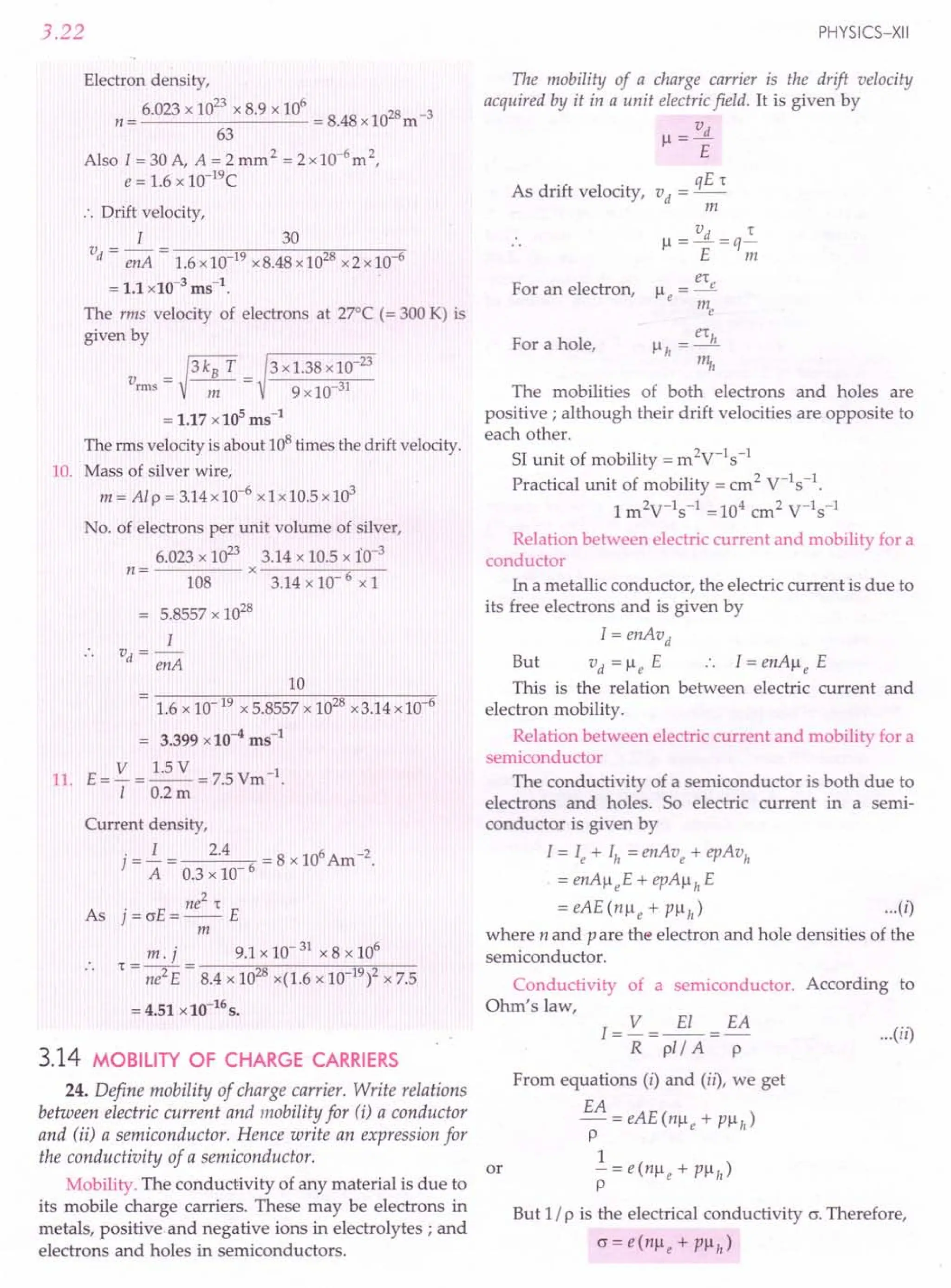
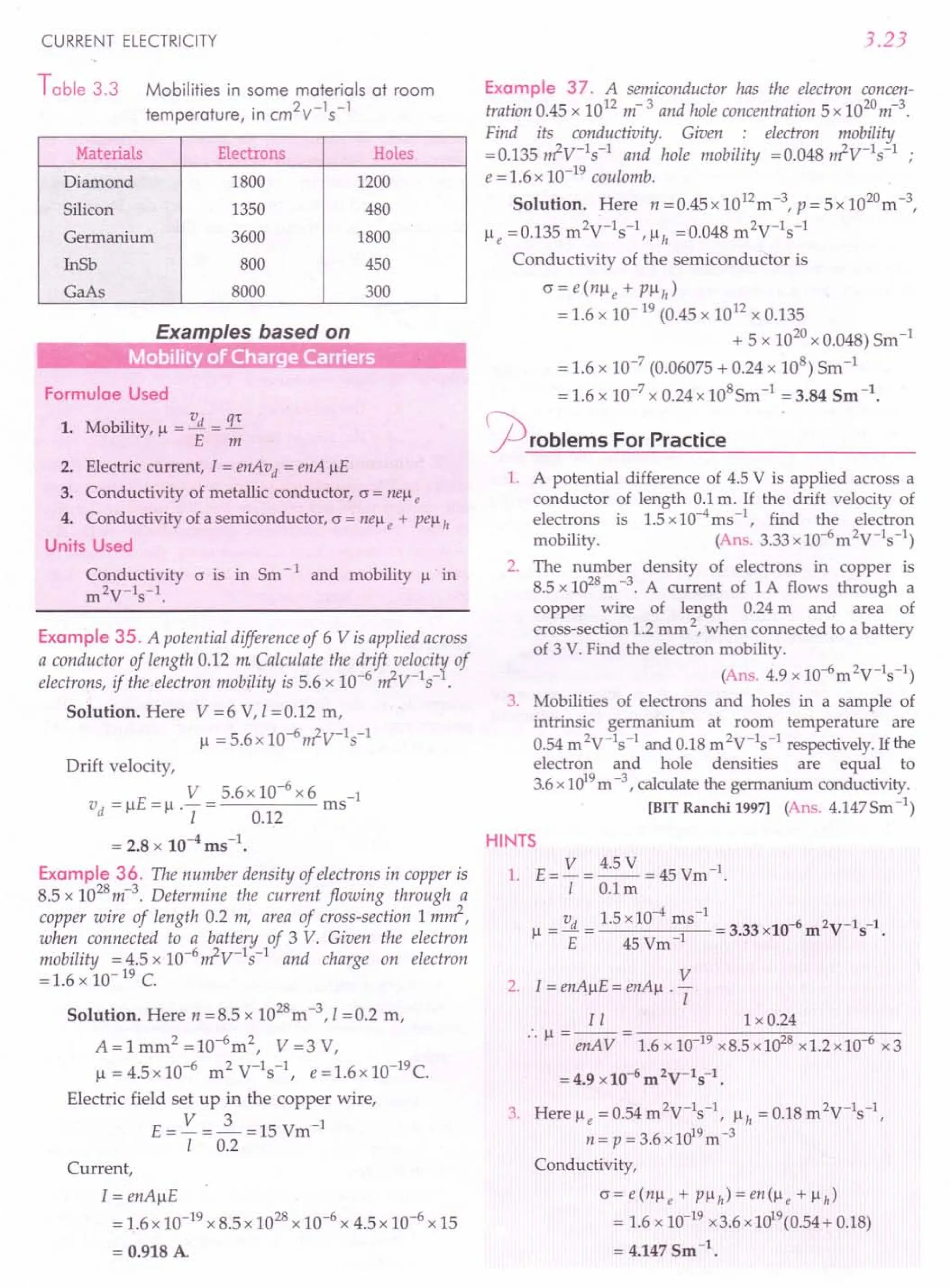
![3.24
3.15 TEMPERATURE DEPENDENCE OF
RESISTIVITY
25. Explain the variation of resistivity of metals,
semiconductors, insulators and electrolytes with the
change in temperature. Define temperature coefficient of
resis tivi ty.
Temperature dependence of resistivity. The resisti-
vity of any material depends on the number density n
of free electrons and the mean collision time 1:.
m
P=--
ne2
1:
1. Metals. For metals, the number density n of free
electrons is almost independent of temperature. As
temperature increases, the thermal speed of free elec-
trons increases and also the amplitude of vibration of
the metal ions increases. Consequently, the free elec-
trons collide more frequently with the metal ions. The
mean collision time 1: decreases. Hence the resistivity of a
metal (p oc 1/1:) increases and the conductivity decreases
with the increase in temperature.
For most of the metals, resistivity increases linearly
with the increase in temperature, around and above
the room temperature. In such cases, resistivity P at
any temperature T is given by
P = Po [1 + a. (T - To)] ...(1)
where Po is the resistivity at a lower reference
.temperature to (usually 20° q and a. is the coefficient
of resistivity. Obviously,
P -P
a.= 0
Po (T - To)
1 dp
Po 'dT
Thus, the temperature coefficient of resistivity a.
may be defined as the increase in resistivity per unit
resistivity per degree rise in temperature.
The unit of a. is °C-1
. For metals a. is positive. For
many metallic elements, a. is nearly 4x10⁻³°C-1. For
such conductors, the temperature dependence of p at
low temperatures is non-linear. At low temperatures,
the resistivity of a pure metal increases as a higher power
of temperature, as shown for copper in Fig. 3.20(a).
E
~
a: 1.20
eo
I;::
a: .c
:~ 1.
.;;;
~ 1.00
~ 0.4
(a)
o 50 100 150
Temperature T(K) ....•
200 400 600 800
Temperature T (K) ....•
Fig. 3.20 (a) Variation of resistivity p of copper with
temperature. (b) Variation of resistivity p of
nichrome with temperature.
PHYSICS-XII
Alloys have high resistivity. The resistivity of nich-
rome has weak temperature dependence [Fig. 3.20(b)]
while that of manganin is almost independent of
temperature. At absolute zero, a pure metal has negli-
gibly small resistivity while an alloy (like nichrome)
has some residual resistivity. This fact can be used to
distinguish a pure metal from an alloy.
I
As R = p - i.e., R oc p
A
Thus equation (1) can be written in terms of resis-
tances as
(b)
R, = Ro (1 + a. t)
where Rt
= the resistance at tOC
Ra = the resistance at O°c, and
t = the rise in temperature.
2. Semiconductors and insulators. In case of insu-
lators and semiconductors, the relaxation time 1: does
not change with temperature but the number density
of free electrons increases exponentially with the
increase in temperature. Consequently, the conductivity
increases or resistivity decreases exponentially with
the increase in temperature.
The number density of electrons at temperature T is
given by
(T)
_ -Eg /kBT
n - no e
where kB is the Boltzmann constant and Eg
is the
energy gap (positive energy) between conduction and
valence bands of the substance.
1 .
As p oc - ,so we can wnte
n
_1_ = ~ e-Eg /kBT
p (T) Po
E /k T
or p (T) = Po e g B
This equation implies that the resistivity of semicon-
ductors and insulators rapidly increases with the decrease
in temperature, becoming infinitely large as T ~ O.
At room temperature, kBT =0.03 eV. Whether the
non-conducting substance is an insulator or a semi-
conductor, depends on the size of the energy gap, Eg:
(i) If E ::;1 eV, the resistivity at room temperature
is ~ot very high and the substance is a
semiconductor .
(ii) If E > 1 eV, the resistivity at room temperature
is v~ry high (-103
n m) and the substance is an
insulator.
The coefficient of resistivity (u) is negative for
carbon and semiconductors i.e., their resistivity
decreases with temperature, as shown in
Fig. 3.21.](https://image.slidesharecdn.com/slaroraclass12thphysicsbyrockytrickster-250318042948-c8b51a5a/75/SL-ARORA-CLASS-12TH-PHYSICS-BY-ROCKY-TRICKSTER-pdf-209-2048.jpg)
![CURRENT ELECTRICITY
fp
Fig. 3.21 Resistivity of a semiconductor decreases
rapidly with temperature.
3. Electrolytes. As the temperature increases, the
interionic attractions (solute-solute, solvent- solute and
solvent-solvent types) decrease and also the viscous
forces decrease, the ions move more freely. Hence
conductivity increases or the resistivity decreases as
the temperature of an electrolytic solution increases.
26. Why alloys like constantan or manganin are used
for making standard resistors?
Use of alloys in making standard resistors. Alloys
like constantan or manganin are used for making stan-
dard resistance coils because of the following reasons:
(i) These alloys have high value of resistivity.
(ii) They have very small temperature coefficient.
So their resistance does not change appreciably
even for several degrees rise of temperature.
(iii) They are least affected by atmospheric
conditions like air, moisture, etc.
(iv) Their contact potential with copper is small.
Examples based on
Tern erarure Variarion of Resisrance
Formulae Used
Temperature coefficient of resistance
a= ~-~
~ (t2 - t1)
Ht1 =O°Candt2
=tOC, then
R,-R
a = 0 or R, = ~ (1+ at)
Ro xt
Units Used
Resistances are in 0, temperatures in °C or K.
Example 38. (i) At what temperature would the resistance
of a copper conductor be double its resistance at O°C ?
tii) Does this temperature hold for all copper conductors
regardless of shape and size ?
Given afor Cu =3.9·x 10-3
°C-1
.
R-R 2R-R 1
Solution. (i) a = ''2 1 = 0"0 =-
R1(t2-t1) Ro(t-O) t
3.25
t=2.= 1 =2560C
a 3.9 x 10- 3
Thus the resistance of copper conductor becomes
double at 256°C
(ii) Since a does not depend on size and shape of
the conductor, so the above result holds for all copper
conductors.
Example 39. The resistance of the platinum wire of a
platinum resistance thermometer at the ice point is 50 and
at steam point is 5.39 O. When the thermometer is inserted
in a hot bath, the resistance of the platinum wire is 5.975 O.
Calculate the temperature of the bath. [ TERT]
Solution. Here Ro = 5 0, RlOO = 5.23 0, Rt
= 5.795 0
As R, = Ro (1+ at)
Rt - Ro = Ro at
and RlOO - Ro = Ro a x 100
On dividing (i) by (ii), we get
Rt - Ro = .L.
RlOO - Ro 100
R - R
t = t "0 x 100
R100 - Ro
= 5.795 - 5 x 100 = 0.795 x 100 = 345.650C
5.23 -5 0.23
...(i)
...(ii)
or
Example 40. A nichrome heating element connected to a
220 V supply draws an initial current of2.2 A which settles
down after afew seconds to a steady value of 2.0 A. Find the
steady temperature of the heating element. The room
temperature is 30° C and the average temperature coefficient
of resistance of nichrome is 1.7 x 10⁻⁴
per°C.
Solution. Here V =220 V, II =2.2 A, I2 =2.0 A,
a = 1.7 x 1O-4°C-1
Resistance at room temperature of 30°C,
R = V =220 =1000
1 II 2.2
Resistance at steady temperature,
~ = V =220 =1100
12 2.0
R - R
a = ''2 1
Rl (t2 - t1)
_ _ ~ - Rl _ 110 -100 -5880C
t2 tl - - -
Rl a 100 x 1.7 x 10- 4
As
Steady temperature,
t2 = 588 + tl = 588 + 30 = 618°C.
Example 41. An electric toaster uses nichrome (an alloy of
nickel and chromium) for its heating element. When a
negligibly small current passes through it, its resistance at](https://image.slidesharecdn.com/slaroraclass12thphysicsbyrockytrickster-250318042948-c8b51a5a/75/SL-ARORA-CLASS-12TH-PHYSICS-BY-ROCKY-TRICKSTER-pdf-210-2048.jpg)
![3.26
room temperature (27.0°C) is found to be75.3 O. When the
toaster is connected to a 230 V supply, the current settles
after afew seconds to a steady value of 2.68 A. What is the
steady temperature of the nichrome element ? The t'em-
perature coefficient of resistance of nichrome averaged over
the temperature range involved is 1.70 x 10⁻⁴°C-1
.
[NCERT]
Solution. Here R1 =75.3 0, t1 =27°C
R = 230 = 85.8 0 t -?
"2 2.68 '2 - .
_ _ ~ - R1 _ 85.8 -75.3 -8200C
t2 t1 - - -
R1 a 75.3 x 1.70 x 10- 4
Steady temperature,
t2 '" 820 + t1 =820 + 27 = 847°C.
At the steady temperature, the heating effect due to
the current equals heat loss to the surroundings.
Example 42. The resistance of a tungsten filament at
150°C is 133 ohm. What will be its resistance at 500°C?
The temperature coefficient of resistance of tungsten is
0.0045 peri C.
Solution. Here R1S0
=1330, a =0.0045°C, Rsoo=?
or
R, = Ra (1 + at)
R1S0
= Ra (1 + a x 150)
133 = Ro (1 + 0.0045 x 150)
Rsoo = Ra (1 + a x 500)
Rsoo= Ra (1 + 0.0045 x 500)
Dividing (2) by (1), we get
Rsoo = 1 + 0.0045 x 500 = 3.25
133 1 + 0.0045 x 150 1.675
Rsoo= 3.25 x 133 = 258 O.
1.675
Now
and
or
or
Example 43. The resistance of a conductor at 20°C is
3.150 and at 100°C is 3.75 O. Determine the temperature
coefficient of resistance of the conductor. What will be the
resistance of the conductor at O°C ?
Solution. Rl = Ra (1 + a t1
) and ~ = Ra (1 + a t2
)
On dividing,
..& = 1+ a tl
~ 1+ a t2
or R1 (1 + a t2
) = ~ (1 + a t1)
a= ~-R1
Rl t2 --:~ t1
or
Here tl =20°C, Rl =3.150,
t2 = 100°C, ~ = 3.750
PHYSICS-XII
3.75 -3.15
.. a = ---------
(3.15 x 100) - (3.75 x 20)
0.60 = 0.60 = 0.00250C-1•
315 -75 240
R =~ 3.15 =3.00.
o 1 + a tl 1 + 0.0025 x 20
Example 44. A standard coil marked 20 is found to have
a resistance of 2.1180 at30° e. Calculate the temperature at
which the marking is correct. The temperature coefficient of
the resistance of the material of the coil is 0.0042 °C-1
.
Solution. Rl = Ra (1+ a t1
) and ~ = Ra (1+ a t2
)
Rl = 1+ a tl
~ 1+ a t2
Here, Rl =2 0, ~ =2.1180, t2 =30°C, tl =?
2 = 1 + 0.0042 x tl = 1 + 0.0042 x tl
2.118 1 + 0.0042 x 30 1.126
or 1 + 0.0042 t = 2 x 1.126 = 2.252
1 2.118 2.118
•• t = _1_ [2.252 -1] = 0.104 ::.150C
1 0.0042 2.118 0.0042 x 2.118
...(1)
i.e., the marking will be correct at 15°C
Example 45. A potential difference of 200 V is applied to a
coil at a temperature of 15°C and the current is 10 A. What
will be the mean temperature of the coil when the current has
fallen to 5 A, the applied voltage being same as before ?
Given a =_1_oC-1 atO°e.
234
Solution. In the second case, the current decreases
due to the increase in resistance on heating.
V 200
Now R1S = I =10 =200
Let t be the temperature at which current falls to
5 A. Then
...(2)
or
R = 200 =400
t 5
As Rf
= Ra (1+ at)
R1S = Ra (1+ ~) or
234
Rt = Ra ( 1+ 2~4) or
Dividing (2) by (1),
2=234+t
249
t = 498 -234 = 264°C.
...(1)
R x 249
20 = _"-"----0 __
234
40 = Ro (234 + t) ...(2)
234](https://image.slidesharecdn.com/slaroraclass12thphysicsbyrockytrickster-250318042948-c8b51a5a/75/SL-ARORA-CLASS-12TH-PHYSICS-BY-ROCKY-TRICKSTER-pdf-211-2048.jpg)
![CURRENT ELECTRICITY
Example 46. The resistances of iron and copper wires at
20°C are 3.9 0 and 4.1 0 respectively. At what temperature
will the resistances be equal ? Temperature coefficient of
resistivity for iron is 5.0 x 10⁻³ K-1
and for copper it is
4.0 x 10⁻³ K-1
. Neglect any thermal expansion.
Solution. Let resistance of iron wire at tOe
= Resistance of copper wire at tOe
~o [1+ a (t -20)] = R;o [1+ a' (t -20)]
3.9[1 + 5.0 x 10-t -20)] = 4.1 [1 + 4.0 x 10⁻³
(t -20)]
[3.9 x 5 - 4.1x 4]x 10-3
x (t -20) = 4.1-3.9
t -20 = 0.2 =64.5
3.1 x 10- 3
t = 64.5 + 20 = 84.5°C.
Example 47. A metal wire of diameter 2 mm and length
100 m has a resistance of 0.54750 at 20°C and 0.805 0 at
150°C. Find (i) the temperature coefficient of resistance
tii) resistance at O°C (iii) resistivities at 0° and 20°C.
Solution. Here r = 1 mm = 10-3
m, 1=100 m,
t1 =20°C, R1 =0.54750, t2 =150°(, ~ =0.8050
(i) Temperature coefficient of resistance is
~ - R1 0.805 - 0.5475
a= =------
R1 (t2 - t1) 0.5475 (150 - 20)
= 3.6 x 10⁻³⁰(-1.
(ii) Resistance at OO( is
R = ~ = 0.5475 = 0.5475
o l+at1
1+3.6xl0-3x20 1.072
= 0.51070.
(iii) Resistivity at O°c,
_ Ra A _ Ra x 11:? _ 0.5107x3.14x (10-3)2
Po - -1- - I - 100
= 1.60 x 10⁻⁸
Om.
Resistivity at 200
( is
P20 = Po (1 + a t)
= 1.60 x 10⁻⁸ (1 + 3.6 x 10-3 x 20)
= 1.60 x 10-8 x 1.072 = 1.72 x 10⁻⁸ Om.
j2)roblems ForPractice
1. A platinum wire has a resistance of 100 at Oo( and
of 20 0 at 273°C. Find its temperature coefficient of
resistance. (Ans. _1_ 0C-1)
273
2. A standard coil marked 30 is found to have a true
resistance of 3.115 0 at 300 K. Calculate the tempe-
rature at which marking is correct. Temperature
coefficient of resistance of the material of the coil is
4.2 x 10⁻³
°e1
. (Ans. 290.2 K)
3.27
3. The resistance of a silver wire at O°Cis 1.25O. Up to
what temperature it must be heated so that its
resistance is doubled? The temperature coefficient
of resistance of silver is 0.00375 °C-1
. Will the
temperature be same for all silver conductors of all
shapes? (Ans. 26~ C, Yes)
4. The resistance of a coil used in a platinum-resis-
tance thermometer at O°Cis 3.000 and at 100°C is
3.75 O. Its resistance at an unknown temperature is
measured as 3.15 O. Calculate the unknown
temperature. (Ans.200q
5. The temperature coefficient of a resistance wire is
0.0012.soC-1
. At 300 K, its resistance is 10. At what
temperature the resistance of the wire will be 20 ?
[lIT 80]
(Ans. 1127 K)
6. The temperature coefficient of resistivity of copper
is 0.004°C-1
. Find the resistance of a 5 m long
copper wire of diameter 0.2 mm at 100°C, if the
resistivity of copper at O°Cis 1.7 x 10⁻⁸
Om.
(Ans. 3.80)
HINTS
1. a = Rf - Ra = 20 - 10 = ~ 0C1.
Ra x t 10 x 273 273
2. Here t = 300 - 273 = 27°C
Rz7 = Ra (1 + a x 27)
3.115= Ra(1+4.2x10-3 x27)
and 3 = Ra(I + 4.2 x 10⁻³ xt)
Dividing (2) by (1), we get
3 1+4.2xl0-3xt
3.115 = 1+ 4.2 x10-3
x27
...(1)
...(2)
5.
This gives,
t = 17.2°C = 17.2 + 273 = 290.2 K.
3, Proceed as in Example 38, page 3.25.
4. Rf
= Ra (1+ at)
~oo = Ra (1+ a x 100)
3.75 = 3.00 (1 + a x 100)
3.75 _ 1= 100a
3
a = ~ = 0.0025b
C1
3 x 100
and
R - R
t =_f_"_O
Ra xa
300 K = 300 - 273 = 27°C
Rz7 = Ra (1 + a x 27) = 10
Rf
= Ra (1 + a x t) = 20](https://image.slidesharecdn.com/slaroraclass12thphysicsbyrockytrickster-250318042948-c8b51a5a/75/SL-ARORA-CLASS-12TH-PHYSICS-BY-ROCKY-TRICKSTER-pdf-212-2048.jpg)
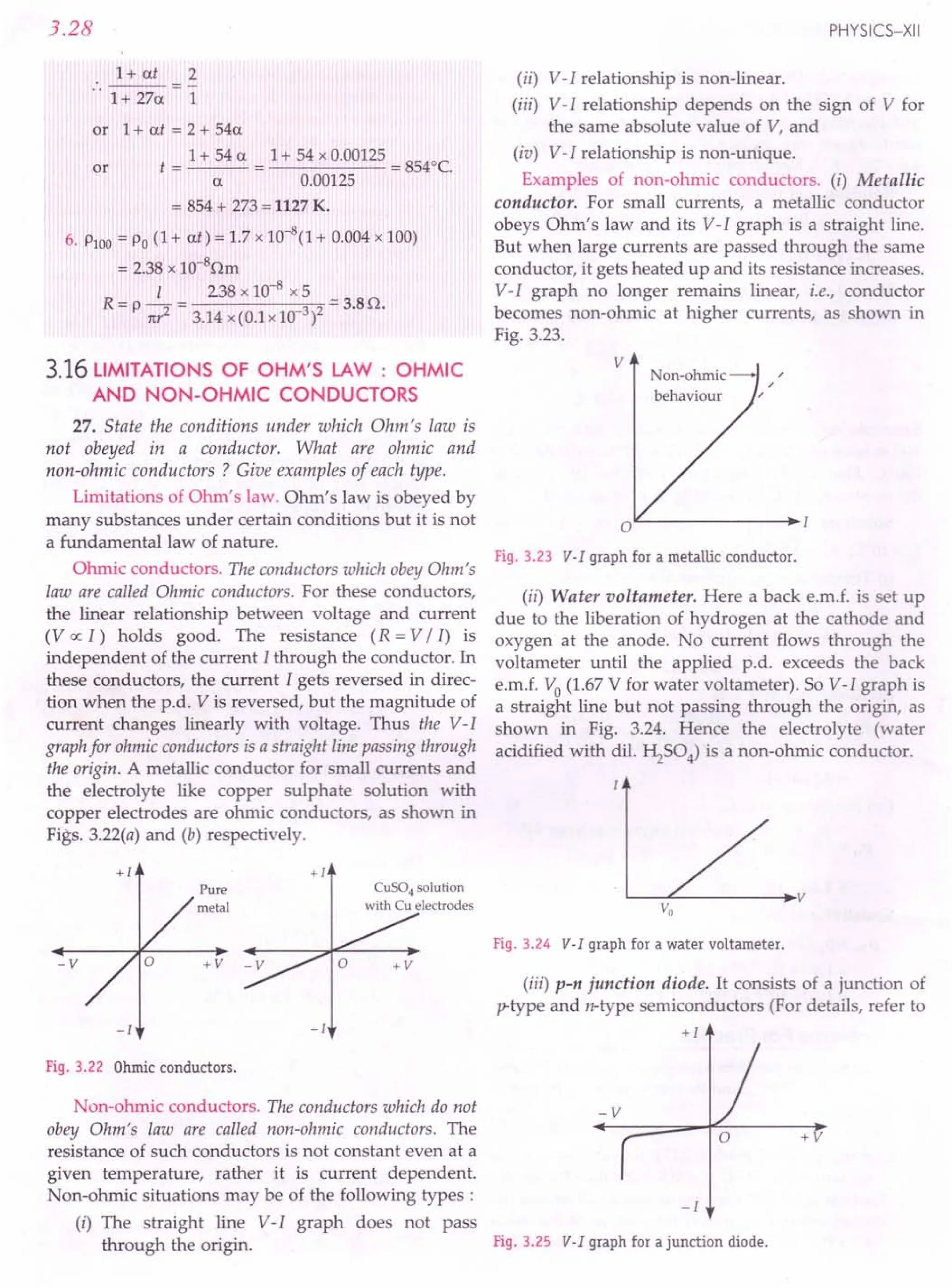
![CURRENT ELECTRICITY
chapter 14 Vol. II). A voltage V is applied across the
junction. The resulting current I is shown in Fig. 3.25.
Obviously, I is not proportional to V. Further, very
little current flows for fairly high negative voltage
(called negative bias) and a current begins to flow for
much smaller positive (forward) bias. Thus the junction
diode allows current to flow only in one direction i.e., it
acts as a rectifier (converts a.c. into d.c.).
(iv) Thyristor. It consists of four alternate layers of p
and n-type semiconductors. Its V-I relationship is as
shown in Fig. 3.26. It can be easily seen that (a) the V-I
relation is non-linear, (b) V-I relationship is different
for positive and negative values of V, and (c) in certain
portions, there are two or more values of current for
the same value of voltage, i.e., the V-I relationship is
not unique. The region AB is interesting because the
current carried by the device increases as the voltage
decreases, i.e., a is negative in this region.
+v
-v
-1
Fig. 3.26 V-I curve for a thyristor.
(v) Gallium arsenide. Fig. 3.27 shows the V-I graph
for the semiconductor GaAs. It exhibits non-linear
behaviour. Moreover, after a certain voltage, the
current decreases as the voltage increases. That is, if !1V
is positive then M is negative and hence the effective
resistance (= !1V / M) is negative.
I
(rrtA)"]
~
•...
;:J
u
•..
'"
~ .§
,01)
c '"
o •.•
Z
'" '"
: E ~ s:
I rl..a.J "b.ol
I ~.~ Q) I
I Z ~ ~ :
I
I
I
I
I
I
I
I
Voltage V (V) ~
Fig. 3.27 V-I graph for GaAs.
3.29
3.17 SUPERCONDUCTIVITY
28. What is superconductivity ? What is its cause ?
Superconductivity. In 1911,Prof Kamerlingh Onnes at
the University of Leiden (Holland), observed that the
resistivity of mercury suddenly drops to zero at a tempe-
rature of about 4.2 K and it becomes a superconductor.
0.16
t
a
~ 0.08
o 2 4 6
T(K)~
Fig. 3.28 Mercuryloses complete resistance at 4.2 K.
The phenomenon of complete loss of resistivity by
certain metals and alloys when they are cooled below
a certain temperature is called superconductivity.
The temperature at which a substance undergoes a
transitionfrom normal conductor to superconductor in
a zero magnetic field is called transition or critical
temperature (Te).
A current once set up in a superconductor persists
for a very long time without any apparent change in its
magnitude.
Cause of superconductivity. It is believed that near
the transition temperature, a weak attractive force acts
on the electrons which brings them closer to form
coupled pairs. Such coupled pairs are not deflected by
ionic vibrations and so move without collisions.
29. What is Meissener effect in superconductors ?
Meissener effect. In 1933, Meissner and Ochsenfeld
observed that if a conductor is cooled in a magnetic
field to a temperature below the transition tempe-
rature, then at this temperature, the lines of magnetic
induction Bare pushed out of the specimen, as shown
in Fig. 3.29. Thus Bbecomes zero inside a supercon-
ducting specimen.
...•
B
Fig. 3.29 Meissner effect in a superconductor.](https://image.slidesharecdn.com/slaroraclass12thphysicsbyrockytrickster-250318042948-c8b51a5a/75/SL-ARORA-CLASS-12TH-PHYSICS-BY-ROCKY-TRICKSTER-pdf-214-2048.jpg)
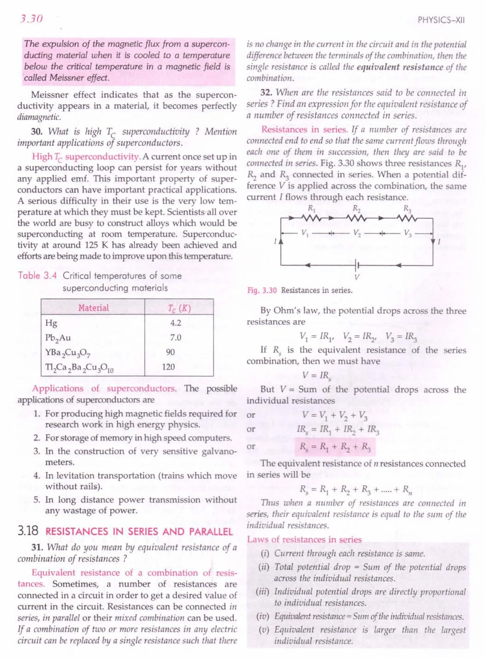
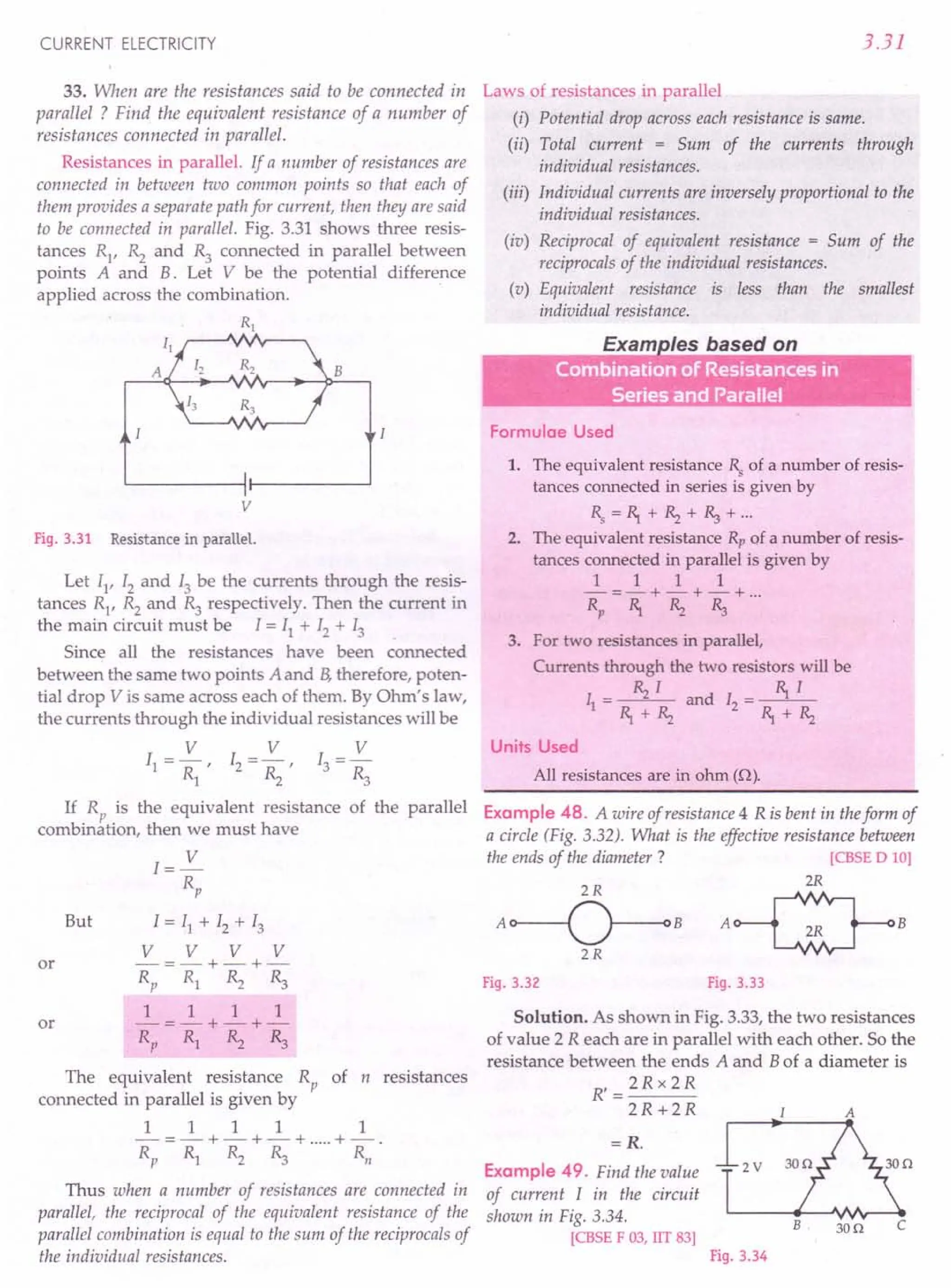
![3.32
Solution. In the given circuit, the resistance of arm
ACB (30 + 30 = 600) is in parallel with the resistance of
arm AB(=30 0).
Hence the effective resistance of the circuit is
R = 30 x 60 =20 0
30 +60
V 2
Current, I = - = - = 0.1 A
R 20
PHYSICS-XII
c
A E
Fig. 3.36
the voltage drop across the
given below with e = 60 V,
Example 50. Determine
resistor R} in the circuit
RI =180, Rz =100.
Solution. As the resistances R3 and R4 are in series,
their equivalent resistance
= 5 + 10 =150.
e=60V
Fig. 3.35
The series combination of R3 and R4 is in parallel
with Rz. Their equivalent resistance is
R,=10x15 =150=60
10 + 15 25
The combination R' is in series with RI
.
.'. Total resistance of the circuit,
R =6 + 18 =240
I = ~ = 60 = 2.5 A
R 24
Current,
•. Voltage drop across R}
= IRI = 2.5 x 18 V = 45 V.
Example 51. A letter A consists of a uniform wire of
resistance 1ohm per em. The sides of the letter are each20 em
long and the cross-piece in the middle is10 em long while the
apex angle is60°. Find the resistance of the letter between the
two ends of the legs.
Solution. Clearly,
AB= BC=CD= DE= BD=10 em
R} = Rz = ~ = R4 = Rs = 10 0
As Rz and ~ are in series, their combined resis-
tance = 10 + 10 = 20 O. This combination is in parallel
with Rs (=100).
Hence resistance 'between points Band D is
given by
1 1 1 3
-=-+-=- or
R 20 10 20
Now resistances RI
, R and R4 form a series com-
bination. So resistance between the ends A and E is
R' = 10 + 20 + 10 = 26.67 O.
3
Example 52. A set of n identical resistors, each of resis-
tance R0, when connected in series have an effective resis-
tance X 0 and when the resistors are connected in parallel,
their effective resistance is YO. Find the relation between
R,X and Y.
Solution. The effective resistance of the n resistors
connected in series is
X = R + R + R + .....n terms = nR
The effective resistance Y of the n resistors
connected in parallel is given by
1 1 1 1 n
- = - + - + - + ....n terms =-
Y R R R R
Y= R
n
XY = nR. R = R2.
n
or
Example 53. A parallel combination of three resistors takes
a current of 7.5 A from a 30 V supply. If the two resistors
are 10 0 and 120, find the third one.
[Punjab 91; Haryana 94]
Solution. Here Rp = V = ~ = 4 0
I 7.5
1 1 1 1
But -=-+-+-
Rp R} ». ~
1 1 1 1
-=-+-+-
4 10 12 ~
1 1 11 1
---=-
~ 4 60 15
or
or .. ~ =150.
Example 54. When a current of 0.5 A is passed through
two resistances in series, the potential difference between the
ends of the series arrangement is 12.5 V. On 'connecting
them in parallel and passing a current of 1.5 A, the potential
difference between their ends is 6 V. Calculate the two
resistances.](https://image.slidesharecdn.com/slaroraclass12thphysicsbyrockytrickster-250318042948-c8b51a5a/75/SL-ARORA-CLASS-12TH-PHYSICS-BY-ROCKY-TRICKSTER-pdf-217-2048.jpg)
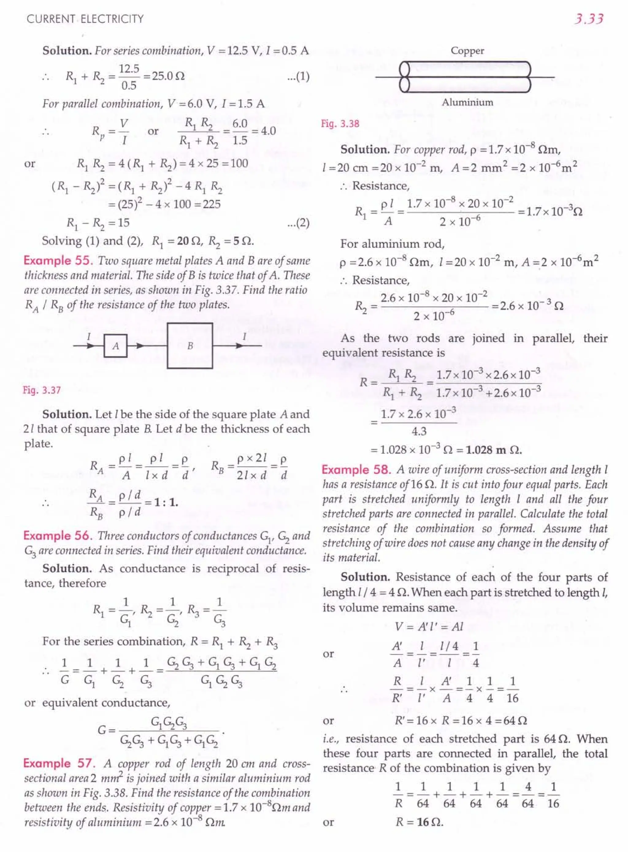
![3.34
Example 59. Find, in the given network of resistors, the
equivalent resistance between the points A and B, between A
and D, and between A and C. [lIT]
Solution. The resistors 0 70 C
AD (= 3 0) and DC (= 7 0)
are in series to give a total
resistance R' =100. The 30 50
resistance R' (= 10 0) and
the resistor AC(=100)
A B
are in parallel. Their equi-
valent resistance is Fig. 3.39
R" = 10 x 10 = 5 0
10 + 10
Now R" (= 50) and CB (= 50) are in series, their
total resistance R'" = 10 o. Finally, R'" (= 10 0) and
AB (= 100) are in parallel between A and B. Hence the
equivalent resistance between points A and B is
R = 10 x 10 = 5 O.
AB 10 + 10
Similarly,
39 15
RAD =-0 and RAe =-0.
16 4
Example 60. Find the effective resistance between points A
and B for the network shown in Fig. 3.40.
o 30 E
c
F
A 30 B
Fig. 3.40
Solution. At points A and D, a series combination
of 30, 30 resistances (along AC and CD) is in parallel
with 60 resistance (along AD), therefore, resistance
between A and D
1
1 1 0 =30
--+-
3 +3 6
Similarly, resistance between A and E
1
1 1 =30
--+-
3 +3 6
Resistance between A and F
1
1 1 =30
--+-
3 +3 6
PHYSICS-XII
Finally, resistance between A and B
1
1 1 =20
--+-
3 +3 3
Thus the effective resistance between A and B is
20.
Example 61. Find the effective resistance of the network
shown in Fig. 3.41 between the points A and B when (i) the
switch S is open (ii) switch S is closed.
60 120
A B
5
120 60
Fig. 3.41
Solution. (i) When the switch S is open, the resis-
tances of 60 and 12 0 in upper portion are in series,
the equivalent resistance is 18 o. Similarly, resistances
in the lower portion have equivalent resistance of 18 o.
Now the two resistances of18 0 are in parallel between
points A and B.
.'. Effective resistance between points A and B
= 18 x 18 = 90.
18 + 18
(ii) When the switch S is closed, the resistances of
6 0 and 12 0 on the left are in parallel. Their equivalent
resistance is
Similarly, the resistances on the right have
equivalent resistance of 4 o. Now the two resistances
of 4 0 are in series.
.. Effective resistance between points A and B
= 4 + 4 = SO.
Example 62. Calculate the current shown by the ammeter
A in the circuit shown in Fig. 3.42. [CBSE 00 2000]
50
10V
Fig. 3.42](https://image.slidesharecdn.com/slaroraclass12thphysicsbyrockytrickster-250318042948-c8b51a5a/75/SL-ARORA-CLASS-12TH-PHYSICS-BY-ROCKY-TRICKSTER-pdf-219-2048.jpg)
![Now we have resistances of 50,100 and 50 Fig. 3.45
connected in parallel, so Solution. In the steady state (when the capacitor is
1 1 1 1 1 fully charged), no current flows through the branch
R = 5" + 10 + 5" = 2" CEF. The given circuit then reduces to the equivalent
circuit shown in Fig. 3.46.
R = 2 0 3Q
B r-_---.J'AVAiA"v--.[_1-, C
y y y
>
30:
3Q ~ 3Q
A f-[-J_~[-IJViYY"v---D-'---~--"VYV YV'---' F
CURRENT ELECTRICITY
Solution. The equivalent circuit is shown in Fig. 3.43.
10Q 5Q IOQ
10V
Fig. 3.43
For the two 100 resistances connected in parallel,
. . 10 x 10
equivalent resistance = --- = 5 0
10 + 10
For two such combinations connected in series,
equivalent resistance = 5 + 5 = 100
or
Also V= 10V
V 10
.'. Current, I = - = - = 5 A.
R 2
Example 63. Calculate the value of the resistance R in the
circuit shown in Fig. 3.44 so that the current in the circuit is
0.2 A. What would be the potential difference between points
A and B ? [CBSE 00 12]
c
5Q
o
Fig.3.44
Solution.
1 1 1 1
--=-+-+--
RBA 15 30 5+ 5
6 1
-=-
30 5
RBA =50
3.35
By Ohm's law,
0.2A= 6-2 =_4_A
R+I0+5 R+15
4
or R + 15 = - = 20 or R = 50
0.2
VAB = 0.2 x RAB =0.2 x 5 = 1.0 V.
Example 64. In the circuit shown in Fig. 3.45, find the
potential difference across the capacitor.
B
3Q E
c
3Q
A I----'IV.,----'---'/Vr----l F
o
15 V
15 V
I
I
Fig. 3.46
The equivalent resistance of the circuit is
6x3
R=--+3=50
6+3
Current drawn from the battery,
I=15V =3A
50
Current through the branch BCD,
I =_3_. x I=~x3=lA
1 6+3 9
Current through the arm DF = I =3 A
P.D. across the capacitor
= P.D. between points C and F
= P.D. across CD + P.D. across DF
=3x1+3x3=12V.](https://image.slidesharecdn.com/slaroraclass12thphysicsbyrockytrickster-250318042948-c8b51a5a/75/SL-ARORA-CLASS-12TH-PHYSICS-BY-ROCKY-TRICKSTER-pdf-220-2048.jpg)
![3.36
Example 65. A battery of emf 10 V is connected to
resistances as shown in Fig. 3.47. Find the potential
difference between the points A and B.
H1 A s n
B In
c o
3n
lOV
Fig. 3.47
4x4
Solution. Total resistance, R = -- = 2 0
4+4
V lOV
Current I = - = -- = 5 A
, R 20
As each of the two parallel branches has same
resistance (40), so the current of 5 A is divided
equally through them.
Current through each branch =5/2 =2.5 A
Now Vc -VA =2.5xl=2.5V
and Vc - VB= 2.5 x 3 = 7.5 V
VA - VB=(Vc - VB)-(Vc - VA)
= 7.5 -2.5 = 5.0 V.
Example 66. What is the equivalent resistance between
points A and B of the circuit shown in Fig. 3.48? [lIT97]
A~B
Fig. 3.48
Solution. Obviously, the points A and Dare
equipotential points. Also, the points B and C are equal
potential points. So the given network of resistances
reduces to the equivalent circuit shown in Fig. 3.49.
2R
o>----+--c::::-.~o
A ~c B
Fig. 3.49
The three resistances form a parallel combination.
Their equivalent resistance Req is given by
_1_ = _1_ + ~ + ! = 1 + 1 + 2 ~ or R = R / 2.
R 2R 2R R 2R R eq
eq
PHYSICS-XII
Example 67. In the circuit shown in Fig. 3.50, Rl = 4 0,
Rz = ~ = 150, R4 =300 and e = 10 V. Work out the equi-
valent resistance of the circuit and the current in eachresistor.
II RI A [eBSE D 2011]
B
Fig. 3.50
Solution. The resistances Rz, ~ and R4are in parallel.
Their equivalent resistance R' is given by
111111151
-=-+-+-=-+-+-=-=-
R' Rz ~ R4 15 15 30 30 6
or R' =60
The resistance Rl is in series with R'. Hence total
resistance of the circuit is
R=R1
+R'=4+6=100
The current II is the current sent by the cell e in the
whole circuit.
e 10
I =-=-=lA
1 R 10
Potential drop between A and B,
V = II R' = 1x 6 = 6 V
This is the potential drop across each of the resis-
tances Rz, ~ and R4 in parallel. Therefore, currents
through these resistances are
V 6 V 6
12 = - = - = 0.4 A; I3 = - = - = 0.4 A
Rz 15 . ~ 15
V 6
I4 = - = - = 0.2 A.
R4 30
and
Example 68. Find the equivalent resistance between the
points A and B of the network of resistors shown in Fig. 3.51.
Solution. The resistors R2~ 3 0
Rl and Rz are in series.
Their equivalent resistance
=3+3=60
A~----~~r------PB
The 6 0 resistance is in
parallel with ~, so that
their equivalent resistance
=6x3=20
6+3
30
Fig. 3.51
Now the 20 resistance is in series with .R4' So the
total resistance of the upper portion =2 + 3 = 5 O.](https://image.slidesharecdn.com/slaroraclass12thphysicsbyrockytrickster-250318042948-c8b51a5a/75/SL-ARORA-CLASS-12TH-PHYSICS-BY-ROCKY-TRICKSTER-pdf-221-2048.jpg)
![CURRENT ELECTRICITY
Similarly, total resistance of the lower portion
=5Q
Now we have three 5 Q resistors connected in
parallel between the points A and B. Hence the equi-
valent resistance R of the entire network is given by
1 1 1 1 3 5
- = - + - + - = - or R = - Q.
R 5 555 3
Example 69. Find the effective resistance between points A
and B of the network of resistors shown in Fig. 3.52.
c
Solution. By
symmetry, the potential
drops across GC and GD
are equal, so no current
flows in the arm CD.
Similarly, no current A
flows in the arm DE.
Hence the resistances in
the arms CD and DE are
ineffective. The given
circuit reduces to the
equivalent circuit shown
in Fig. 3.53.
H
K
E
Fig. 3.52
G~~VVV- __C~~VVV---oH
H~-oB
AO---+'"
E
Fig. 3.53
Resistance of arm GH = r + r =2 r
rxr r x r
Resistance of arm 1/ = -- + -- = r
r+r r+r
Resistance of arm FK = r + r = 2r
The above three resistances are in parallel between
points A and B and their equivalent resistance R is
given by
1 1 1 1 2
- =- + - + - =- R =0.5 r.
R 2r r 2r r
Example 70. A regular hexagon with diagonals is made of
identical wires, each having same resistance r, as shown in
Fig. 3.54. Find the equivalent resistance between the points
A and B.
Fig. 3.54
3.37
Solution. As shown in Fig. 3.55, the given hexagon
has a line of symmetry C1
C C2
• So all points on this
line have the same potential i.e., potential at C1 =
potential at C = potential at C2
. Hence the points Cl
, C
and C2
can be made to coincide with each other.
A
B
Fig. 3.55
r/2 : r/2
B
r/2 : r/2
After this is done, the circuit splits into identical parts,
joined in series between the points A and B. One such
part between A and C is shown in [Fig. 3.56] which, in
turn, is equivalent to the circuit shown in Fig. 3.57.
0 r/2 4r/3
Cj Cj
r
A
C C
A
4r/3
G
C2 C2
r/2
Fig. 3.56 Fig. 3.57
From Fig. 3.57, the equivalent resistance R' between
the points A and C is given by
~ = ~ + ~ + ~ = 10 or R' = 4r = 0.4 r
R' 4r r 4r 4r 10
As two identical parts AC and CB are joined in
series, hence the equivalent resistance of the entire
circuit between points A and B is
R = R' + R' =0.4 r + 0.4 r = 0.8 r.
Example 71. Find the C
equivalent resistance of
the circuit shown in Fig.
3.58 between the points
A and B. Each resistor
has a resistance r.
A
Fig. 3.58
B](https://image.slidesharecdn.com/slaroraclass12thphysicsbyrockytrickster-250318042948-c8b51a5a/75/SL-ARORA-CLASS-12TH-PHYSICS-BY-ROCKY-TRICKSTER-pdf-222-2048.jpg)
![3.38
Solution. By symmetry, potential drops across AC
and AD are equal. So resistance in arm CD is ineffec-
tive. The given circuit reduces to the equivalent circuit
shown in Fig. 3.59. Clearly the equivalent resistance R
between points A and B is given by
1 1 1 1 4 2
-=-+-+-=-=-
R 2r 2r r 2r r
or R =~ =0.5 r.
2
C r
r 0
A B
Fig. 3.59
Example 72. Find the equivalent resistance of the circuit
shown in Fig. 3.60 between the points P and Q. Each resistor
has a resistance r.
A
p B C Q
Fig. 3.60
Solution. Two resistances along each side of
triangle are in parallel.
The equivalent resistance of each side
r x r r
r+ r 2
The given network of resistances reduces to the
equivalent circuit shown in Fig. 3.6l.
A
P B C Q
Fig. 3.61
The resistances in arms BA and AC are in series.
PHYSICS-XII
Their equivalent resistance =r / 2 + r/ 2 =r. This
resistance is in parallel with the resistance r / 2 along
BC
:. Effective resistance between points P and Q
rx (r/2) r
r+(r/2) 3
~ roblems For Practice
1. Given the resistances of 1n, 2n and 3n. How will
you combine them to get an equivalent resistance of
(i) 11nand (ii) 11n ?
3 5 [CBSEF 2015]
[Ans. (i) parallel combination of In and 2n in
series with 3 n (ii) parallel combination of
2nand 3 n in series with 1n
2. Given three resistances of 30n each. How can they
be connected to give a total resistance of (i) 90n
(ii) 10o (iii) 45o ?
[Ans. (i) in series (ii) in parallel (iii) two
resistances in parallel and one in series]
3. A 5n resistor is connected in series with a parallel
combination of n resistors of 6n each. The equi-
valent resistance is 7n. Find n. (Ans. 3)
4. A uniform wire of resistance 2.20n has a length of
2 m. Find the length of the similar wire which
connected in parallel with the 2 m long wire, will
give a resistance of 2.0n. (Ans. 20 m)
5. A wire of 15n resistance is gradually stretched to
do ble its original length. It is then cut into two
equal parts. These parts are then connected in
parallel across a 3.0 volt battery, Find the current
drawn from ~e battery. [CBSE OD 09]
(Ans. 0.2 A)
6. The total resistance of two resistors when connec-
ted in series is 9n and when connected in parallel,
their total resistance becomes 2 n. Calculate the
value of each resistance. [Punjab 2000]
(Ans. 6n, 3 n)
7, Two wires a ,and b, each of length 40 m and area of
cross-section 10-7
m2 ; are connected in series and a
potential difference of 60 V is applied between the
ends of this combined wire. Their resistances are
respectively 40nand 20n. Determine for each wire
(i) specific resistance, (ii) electric-field, and
(iii) current-density.
[Ans. (i) 1.0 x 10⁻⁷
nm, 5.0 x 10⁻⁸ nm .
(ii) 1.0Vm -1,0.5 Vm-1
(iii) 1.0 x 10⁷ Am -2, 1.0 x 10⁷ Am -2]](https://image.slidesharecdn.com/slaroraclass12thphysicsbyrockytrickster-250318042948-c8b51a5a/75/SL-ARORA-CLASS-12TH-PHYSICS-BY-ROCKY-TRICKSTER-pdf-223-2048.jpg)
![CURRENT ELECTRICITY
8. Three resistances, each of 40, are connected in the
form of an equilateral triangle. Find the effective
resistance between its corners. (Ans.2.670)
9. Two resistors are in the ratio 1 : 4. If these are
connected in parallel, their total resistance becomes
20O. Find the value of each resistance.
[Punjab 2000]
(Ans. 250,1000)
10. Five resistors are connected as shown in Fig. 3.62.
Find the equivalent resistance between the points B
and C. [Punjab 011
(Ans. 70/190)
A 9n B
3n 5n
o zo
Fig.3.62
11. Four resistors of 120 each are connected in parallel.
Three such combinations are then connected in
series. What is the total resistance? If a battery of
9 V emf and negligible internal resistance is
connected across the network of resistors, find the
current flowing through each resistor. [Haryana 02]
(Ans. 90, 0.25 A)
12. If the reading of the ammeter ~ in Fig. 3.63is 2.4A,
what will the ammeters Az and ~ read? Neglect the
resistances of the ammeters. (Ans. 1.6 A, 4.0 A)
II 20n
~"""-'V./r---{Al
IOn
Fig.3.63
13. The resistance of the rheostat shown in Fig. 3.64 is ...
(l
30o. Neglecting the meter resistance, find the
minimum and maximum current through the
ammeter as the resistance of the rheostat is varied.
(Ans. 0.18 A, 1.5 A)
6V
20n
Fig.3.64
3.39
14. Find the current through the 50 resistor in the
circuit shown in Fig. 3.65, when the switch 5 is
(i) open and (ii) closed. [Ans. (i) 0.2 A, (ii) 0.6 A]
5n Ion
5
3V
Fig.3.65
15. The letter A consists of a uniform wire of resistance
10 cm-1. The sides of the letter are 40 ern long and
the crosspiece 10 em long divides the sides in the
ratio 1 : 3 from the apex. Find the resistance of the
letter between the two ends of the legs.
[Punjab 9SC]
(Ans. 66.670)
16. Calculate the equivalent resistance between points
A and Bin eachofthe followingnetworks ofresistors:
[Ans. (a) 120 (b) 40/30 (c) 20
(d) 10/30 (e) 160 if) 50]
sn
sn
A 5n
5n 5n
A B
(a) (b)
C
A
IOn 10n
B
B
(c) (d)
Ion
2Qt87Q
Ao-"".;v~~Nr-"""'V'II'v"""---OB A 10n B
(j)
IOn Ion Ion
Ion
(e)
Fig.3.66](https://image.slidesharecdn.com/slaroraclass12thphysicsbyrockytrickster-250318042948-c8b51a5a/75/SL-ARORA-CLASS-12TH-PHYSICS-BY-ROCKY-TRICKSTER-pdf-224-2048.jpg)
![3.40
17. Calculate the resistance between points A and Bfor
the following networks:
2 4 R
[Ans. (a) "3 0 (b) "3 0 (c) "30 (d) 60]
20
A
(a)
B
(b)
(c)
Fig. 3.67
18. Find the equivalent resistance of the networks
shown in Fig. 3.68 between the points A and B.
4 r
[Ans. (a) "3 r (b) 4 (c) r]
(a) (b)
Fig. 3.68 (c)
PHYSICS-XII
19. Find the potential difference between the points A
and B for the network shown in Fig. 3.69.
(Ans. 8.0 V)
60
2A 2.50
A
30
B
Fig. 3.69
20. In the circuit diagram shown in Fig. 3.70, a volt-
meter reads 30 V when connected across 4000 resis-
tance. Calculate what the same voltmeter reads when
it is connected across 3000 resistance. [lIT 90]
(Ans. 22.5 V)
A
2A
4000
60V
B
Fig. 3.70 Fig. 3.71
21. Find the potential difference between points A and
B i.e., (VA - VB) in the network shown in Fig. 3.71.
[Punjab 93] (Ans. 1 V)
22. In the circuitshown in Fig.3.72,~ = 40, ~ = ~ =50,
R4 = 100 and E. = 6 V. Work out the equivalent resis-
tance of the circuit and the current in each resistor.
[CBSE D 11] (Ans. 60, 1 A, 0.4 A, 0.2 A)
Fig. 3.72 Fig. 3.73
23. Find the equivalent resistance between points A
and B in Fig. 3.73.
(Ans.7.S0)
c
24. Letter A as shown in
Fig. 3.74 has resistances on
each side of arm. Calculate the
total resistance between two
ends of the legs. .
[Himachal 93] A
(Ans. 28.750) F'
19.3.74
E](https://image.slidesharecdn.com/slaroraclass12thphysicsbyrockytrickster-250318042948-c8b51a5a/75/SL-ARORA-CLASS-12TH-PHYSICS-BY-ROCKY-TRICKSTER-pdf-225-2048.jpg)
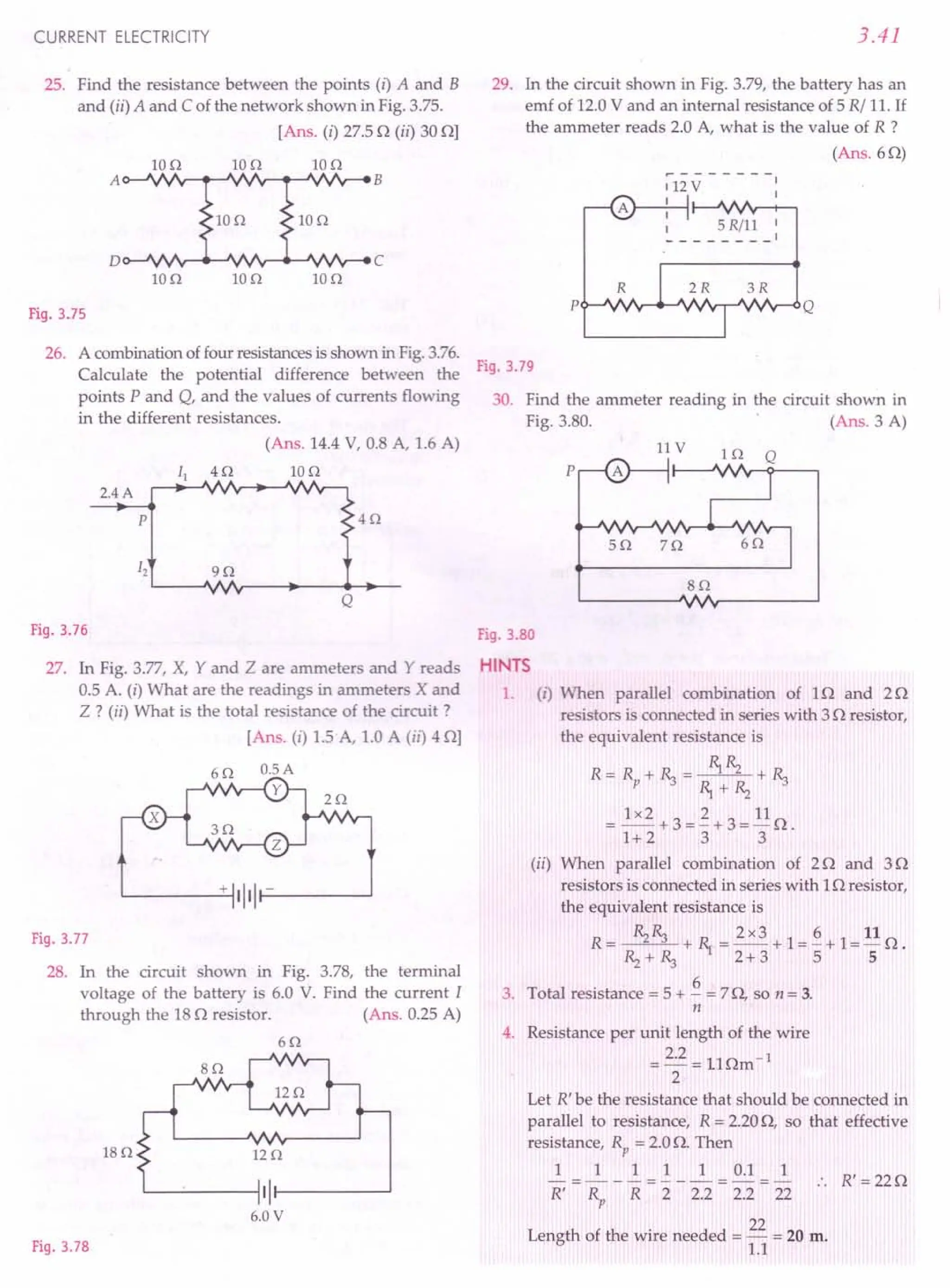
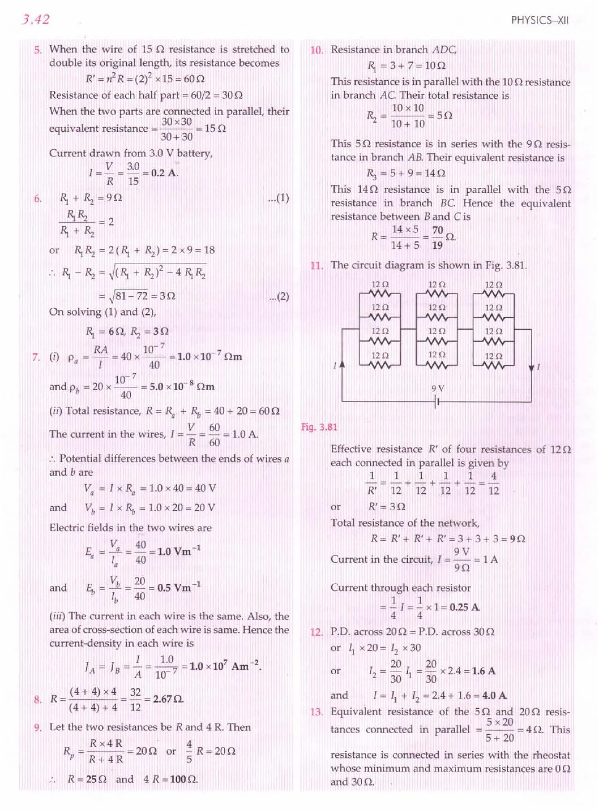
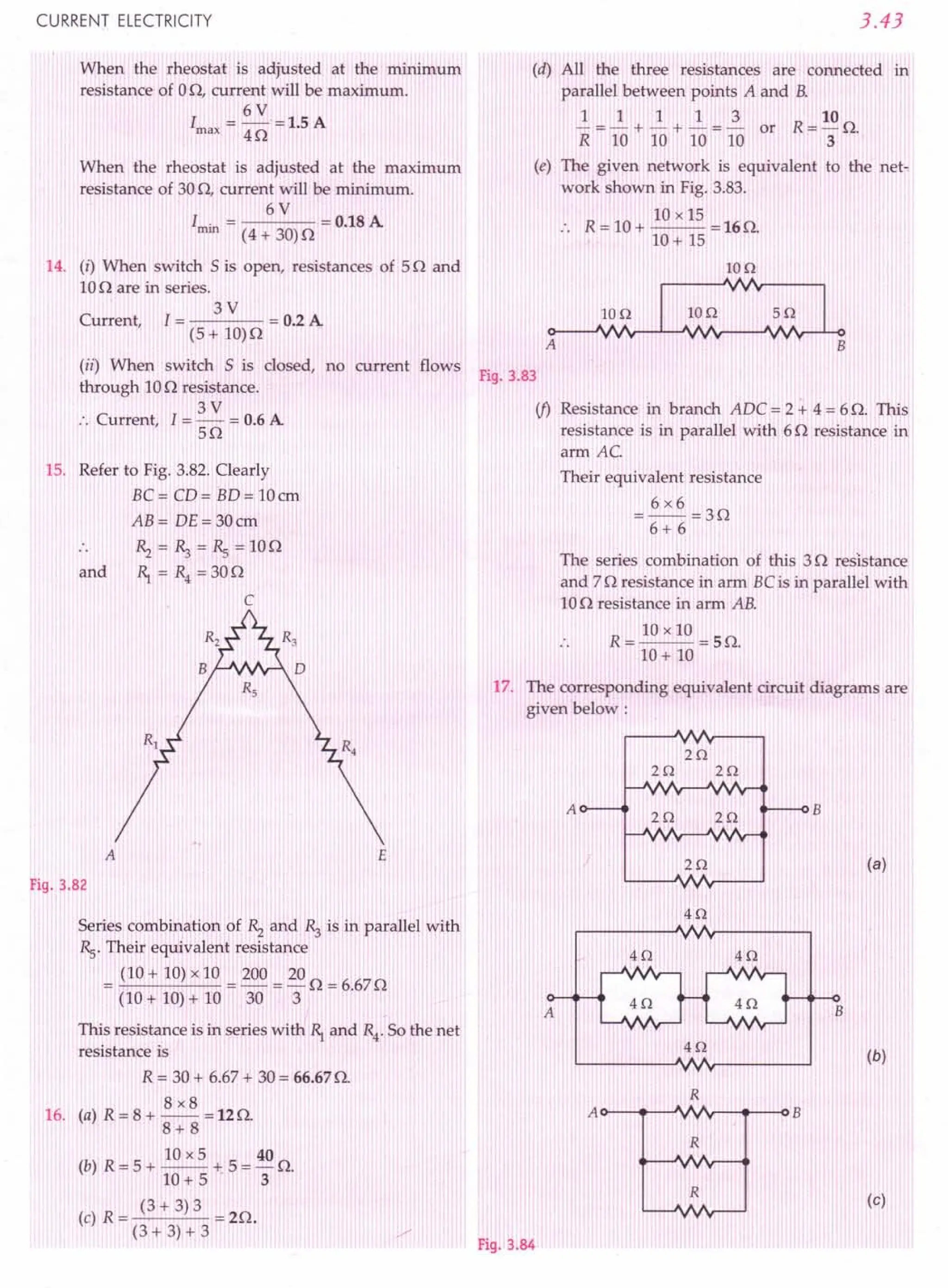
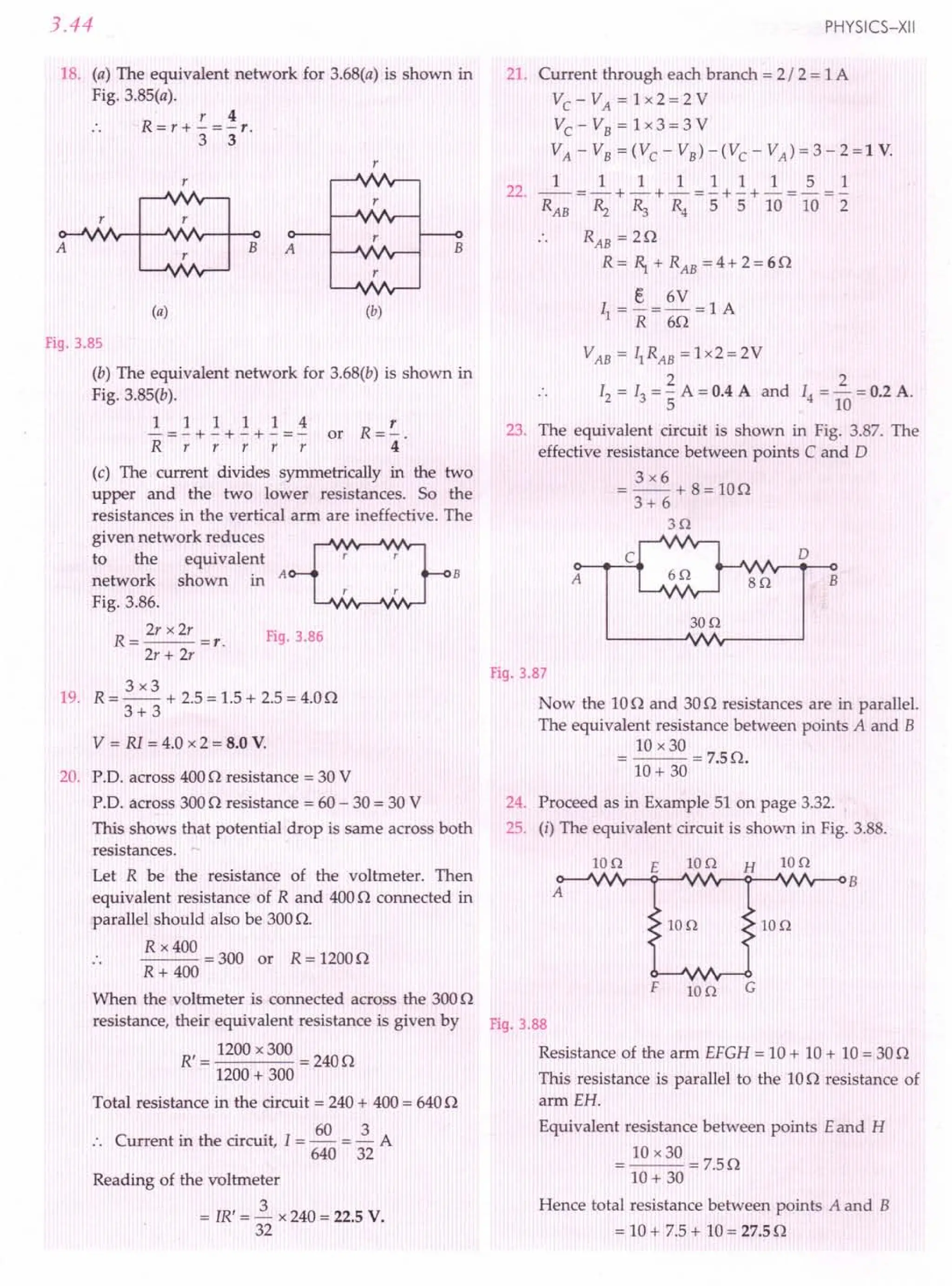
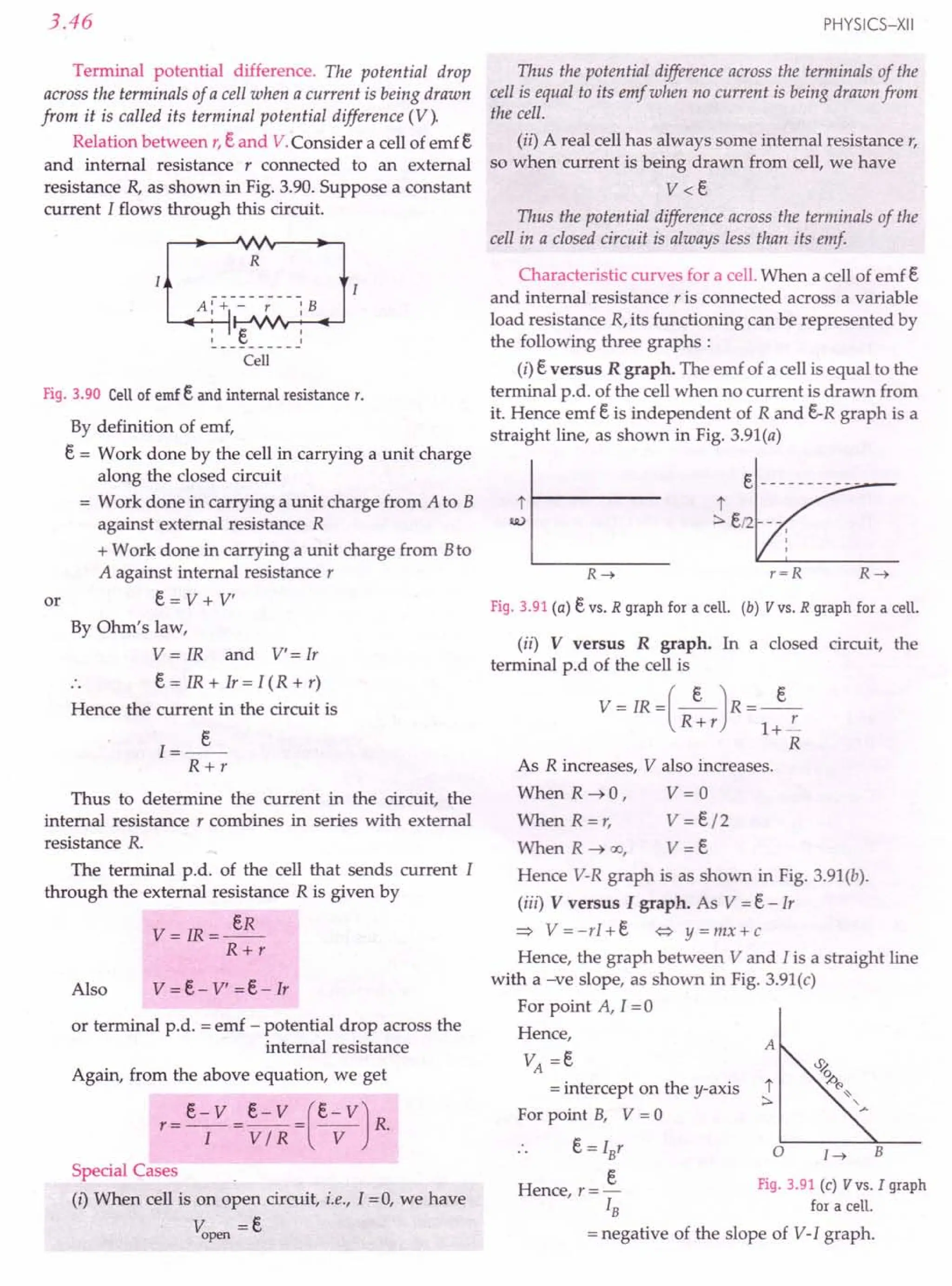
![CURRENT ELECTRICITY
Examples based on
Grouping of Cells
Formulae Used
1. EMF of a cell, e = w
q
2. For a cell of internal resistance r, the emf is
e = V + Ir = I (R + r)
eR
3. Terminal p.d. of a cell, V = IR = --
R+r
4. Terminal p.d. when a current is being drawn from
the cell,
v =e- Ir
5. Terminal p.d. when the cell is being charged,
V =e+ Ir
[
e - V]
6. Internal resistance of a cell, r = R ---v-
Units Used
EMF e and terminal p.d. V are in volt (V), internal
resistance r and external resistance R in n and
current I in ampere (A).
Example 73. For driving a current of 3 Afor 5 minutes in
an electric circuit, 900 J of work is to bedone. Find the emf of
the source in the circuit.
Solution. The amount of charge that flows 'through
the circuit in 5 minutes is
q = I x t = 3 x 5 x 60 = 900 C
As emf is the work done in flowing a unit charge in
the closed circuit, therefore
e = w = 900 J = 1.0 V.
q 900 C
Example 74. A voltmeter of resistance 998 Q is connected
across a cell of emf 2 Vand internal resistance 2 Q. Find the
p.d. across the voltmeter, that across the terminals of the cell
and percentage error in the reading of the voltmeter.
Solution. Here e = 2 V, r = 2 Q
Resistance of voltmeter,
R =998Q
Current in the circuit is
..».
R+r
2V
Cell
:2V
I
2Q :
Voltmeter
R=998Q
(998 + 2)Q
=2 x 10⁻³ A
Fig. 3.92
3.47
The p.d. across the voltmeter is
V= IR
= 2 x 10-3 x 998 = 1.996 V
The same will be the p.d. across the terminals of the
cell. The voltmeter used to measure the emf of the cell
will read 1.996 volt. Hence the percentage error is
e ~ V x 100 = 2 - ~.996 x 100 =0.2%.
Example 75. In the
circuit shown in Fig. 3.93,
the voltmeter reads 1.5 V,
when the key is open. When
the key is dosed, the
voltmeter reads 1.35 V and R
ammeter reads 1.5 A Find
the emf and the internal Fig. 3.93
resistance of the cell.
Solution. When the key is open, the voltmeter
reads almost the emf of the cell.
e = 1.5 V
When the key is closed, voltmeter reads the
terminal potential difference V.
V = 1.35 V, I = 1.5 A, r = ?
r = e - V = 1.5 -1.35 = 0.1 Q.
I 1.5
Example 76. A cell of emf 2 V and internal resistance
0.1 Q is connected to a 3.9 Q external resistance. What will
be the p.d. across the terminals of the cell? [CBSE D OlC]
Solution. Heree=2 V, r=O.lQ, R=3.9Q
e 2
Current, 1=-- = = 0.5 A
R + r 3.9 + 0.1
P.D. across the terminals of the cell,
V = IR =0.5 x 3.9 = 1.95 V.
Example 77. The reading on a
high resistance voltmeter when a
cell is connected across it is
2.2 V. When the terminals of the
cell are also connected to a
resistance of 5Q, the voltmeter
reading drops to 1.8 V. Find the
internal resistance of the cell.
[CBSEOD 10]
Solution. Here e =2.2 V,
Fig. 3.94
R = 5 Q, V = 1.8 V
+
r----{ V}-----,
+ -
R=5Q K
Internal resistance,
r = R (e; VJ = 5 C.21~81.8)Q = 1.1 Q.](https://image.slidesharecdn.com/slaroraclass12thphysicsbyrockytrickster-250318042948-c8b51a5a/75/SL-ARORA-CLASS-12TH-PHYSICS-BY-ROCKY-TRICKSTER-pdf-232-2048.jpg)
![3.48
Example 78. A dry cell of emf 1.6 V and internal resis-
tance 0.10 n is connected to a resistance of R ohm. The
current drawn from the cell is 2.0 A Find the voltage drop
across R.
Solution. Here e = 1.6 V, r = 0.10 n, 1=2.0 A
Voltage drop across R will be
V =e - Ir
= 1.6 - 2.0 x 0.10 = 1.4 V.
Example 79. A battery of e.m.f 't', and internal resistance
'r', gives a current of 0.5 A with an external resistor of
12 ohm and a current of 0.25 A with an external resistor of
25 ohm. Calculate (i) internal resistance of the cell and
(ii) emf of the cell. [CBSE D 02; OD 13C]
Solution. EMF of the cell, e = I (R + r)
In first case, e = 0.5 (12 + r)
in second case, e = 0.25 (25 + r)
0.5 (12 + r) = 0.25 (25 + r)
On solving, we get r = 1n
Hence e = 0.5 (12 + 1) = 6.5 V.
Example 80. A battery of emf 3 volt and internal resis-
tance r is connected in series with a resistor of 55 n through
an ammeter of resistance 1n. The ammeter reads 50 mA.
Draw the circuit diagram and calculate the value of r.
[CBSE D 95 ; Haryana 02]
Solution. Total resistance
= 55 + 1 + r n = 56 + r n
Current 55Q
=50mA
= 50 x 10-3 A
emf r= S V
R
. emf
esistance = ---
Current
R
, ,
, ,
, 1
56 + r = 3 =60 Fig. 3.95
50 x 10-3
r = 60 - 56 = 4 n.
Example 81. (a) A car has afresh storage battery of emf
12 V and internal resistance 5.0 x 10⁻²
n. If the starter
motor draws a current of90 A, what is the terminal voltage
of the battery when the starter is on ?
(b) After long use, the internal resistance of the storage
battery increases to 500 n. What maximum current can be
drawn from the battery ? Assume the emf of the battery to
remain unchanged.
(c) If the discharged battery is charged by an external emf
source, is the terminal voltage of the battery during charging
greater or less than its emf12 V ? [NCERT]
PHYSICS-XII
Solution. (a) Here e = 12 V, I = 90 A,
r = 5.0 x 1O-2
n
.'. Terminal voltage,
V = e - Ir = 12 - 4.5 = 7.5 V.
(b) The maximum current can be drawn from a
battery by shorting it.
Then V =0
e 12
I = - = - A = 24 mA
max r 500
and
Clearly, the battery is useless for starting the car
and must be charged again.
(c) During discharge of the accumulator, the current
inside the cells (of the accumulator) is opposite to what
it is when the accumulator discharges. That is, during
charging, current flows from the + ve to - ve terminal
inside the cells. Consequently, during charging
V = e + Ir
Hence V must be greater than 12 V during charging.
Example 82. A battery of emf 12.0 V and internal resis-
tance 0.5 n is to be charged by a battery charger which
supplies 110 V d.c. How much resistance must be connected
in series with the battery to limit the charging current to
5.0 A ? What will be the p.d. across the terminals of the
battery during charging ?
Solution. For charging, the positive terminal of the
charger is connected to the positive terminal of the battery.
Net emf e' = 110 -12.0 = 98 V
Battery charger
.------f 110 V t-----,
5.0A
r------------ ..
: 12.0 V 0.5 Q: R
'-----',--'-1+ IIII - ,
, :
' J
Fig. 3.96
If R is the series resistor, then the charging current
will be
I=~=~A
R + r R + 0.5
Given 1= 5.0 A, therefore
~ = 5.0 or R =19.1n
R +0.5
The terminal p.d. of the battery during charging is
V = e + Ir = 12.0 + 5.0 x 0.5 = 14.5 V
If the series resistor R were not included in the
charging circuit, the charging current would be 98/0.5
= 196 A, which is dangerously high.](https://image.slidesharecdn.com/slaroraclass12thphysicsbyrockytrickster-250318042948-c8b51a5a/75/SL-ARORA-CLASS-12TH-PHYSICS-BY-ROCKY-TRICKSTER-pdf-233-2048.jpg)
![CURRENT ELECTRICITY 3.49
Example 83. A cell of emf 1.5 V and internal resistance
0.5 Q is connected to a (non-linear) conductor whose V-I
graph is shown in Fig. 3.97(a). Obtain graphically the
current drawn from the cell and its terminal voltage.
I I
Fig. 3.97
Solution. Here E. = 1.5 V, r = 0.5 Q
Terminal voltage of the cell, V = E. - Ir
For different currents, terminal voltages can be
determined as follows:
I=O, V=1.5-0=1.5V
I = 1A, V = 1.5 -1x 0.5 =1.0 V
I = 2 A, V = 1.5 - 2 x 0.5 =0.5 V
I = 3 A, V = 1.5 - 3 x 0.5 =0
The V-I graph for the cell is a straight line AB, as
shown in Fig. 3.97(b). This straight line graph intersects
the given non-linear V-I graph at current = 1 A and at
voltage = 1 V.
:. Current drawn from the cell = 1 A
Terminal voltage of the cell = 1 V.
Example 84. Potential differences across terminals of a cell
were measured (in volt) against different currents (in ampere)
flowing through the cell. A graph was drawn which was a
straight line ABC, as shown in Fig. 3.98. Determine from
the graph
(i) emf of the cell
(ii) maximum current obtained from the cell, and
(iii) internal resistance of the cell. [CBSE D 1IC]
2.0
t
% 1.2
~
:::. 0.8
Fig. 3.98
1.6
I
I
I
---+-------
I
I
I I
---T-------r-------
I I I
I I I
I I I
<. A
0.4
o 0.04 0.12 0.20
I (ampere) ~
0.28
Solution. (I) The potential difference corresponding
to zero current equals the emf of the cell.
:. EMF of the cell, E. = 1.4 V.
(ii) Maximum current is drawn from the cell when
the terminal potential difference is zero.
Imax
= 0.28 A.
(iii) Internal resistance,
E. 1.4 V
r=--=--=SQ.
Imax
0.28 A
Example 85. Find the current drawn from a cell of emf 1 V
and internal resistance 2 /3 Q connected to the network
given below. [CBSE D OlC)
D c
Fig. 3.99
Solution. The equivalent circuit is shown below.
Hl
A B
Hl In
p
In
D c
IV
Fig. 3.100
Resistance in arm AB = 1Q
lxl lxl 1 1
Resistance in arm PQ = -- + -- =- + - =1Q.
1+1 1+1 2 2
Resistance in arm DC = 1Q
These three resistances are connected in parallel.
Their equivalent resistance R is given by
1 1 1 1 3 1
- = - + - + - = - or R = - Q
R 1 1 1 1 3
Current drawn from the cell,
E. 1 V
I = -- = (1 2) = 1 A.
Rw r _+_ Q
3 3](https://image.slidesharecdn.com/slaroraclass12thphysicsbyrockytrickster-250318042948-c8b51a5a/75/SL-ARORA-CLASS-12TH-PHYSICS-BY-ROCKY-TRICKSTER-pdf-234-2048.jpg)
![3.50
Example 86. A uniform wire of resistance 120 is cut into
three pieces in the ratio 1: 2 :3 and the three pieces are
connected toform a triangle. A cell of emf 8 V and internal
resistance 10 is connected across the highest of the three
resistors. Calculate the current through each part of the
circuit. [CBSE OD 13C]
Solution. In Fig. 3.101, RAB = 2 0, R
BC
= 4 0 and
RAC
=60.
B
BV r=10
Fig. 3.101
The series combination of 20 and 40 (of equi-
valent resistance 60) is in parallel with the 60
resistance. The equivalent resistance is
R=6x6=30
6+6
Current, I =_E_ = 8 V =2 A
R + r (3 + 1)0
The resistances R
BAC
and R
BC
of the parallel
branches are equal.
.. IABC = lAC = 1 A.
~roblems For Practice
1. The emf of a cell is 1.5V. On connecting a 140
resistance across the cell, the terminal p.d. falls to
1.4V. Calculate the internal resistance of the cell.
[Haryana 01] (Ans.10)
2. The potential difference across a cell is 1.8V when a
current of 0.5A is drawn from it. The p.d. fallsto 1.6V
when a current of 1.0A is drawn. Find the emf and the
internal resistance of the cell. (Ans. 2.0 V, 0.40)
3. The potential difference of a cell in an open circuit
is 6 V, which falls to 4 V when a current of 2 A is
drawn from the cell. Calculate the emf and the
internal resistance of the cell. (Ans. 6 V, 10)
4. In the circuit shown in Fig. 3.102, the resistance of
the ammeter A is negligible and that of the
voltmeter V is very high. When the switch 5 is open,
the reading of voltmeter is 1.53 V. On closing the
switch 5, the reading of ammeter is 1.00A and that
of the voltmeter drops to 1.03V. Calculate: (i) emf
PHYSICS-XII
of the cell (ii) value of R (iii) internal resistance of
the cell. [Ans. (i) 1.53V (ii) 1.030 (iii) 0.50OJ
5
Fig. 3.102
5. The potential difference between the terminals of a
battery of emf 6.0 V and internal resistance 10
drops to 5.8 V when connected across an external
resistor. Find the resistance of the external resistor.
(Ans.290)
6. The potential difference between the terminals of a
6.0 V battery is 7.2 V when it is being charged by a
current of 2.0 A. What is the internal resistance of
the battery? (Ans. 0.60)
7. A battery of emf 2 V and internal resistance 0.50 is
connected across a resistance of 9.50. How many
electrons pass through a cross-section of the
resistance in 1 second? (Ans. 1.25x 10¹⁸)
8. A cell of emf Eand internal resistance r is connected
across a variable load resistor R It is found that
when R = 40, the current is 1A and when R is
increased to 90, the current reduces to 0.5 A. Find
the values of the emf E and internal resistance r.
[CBSE D 15]
(Ans. 5 V, 10)
9. The emf of a battery is 4.0 V and its internal resis-
tance is 1.5O. Its potential difference is measured
by a voltmeter of resistance 1000O. Calculate the
percentage error in the reading of emf shown by
voltmeter. (Ans. 0.15 %)
10. The emf of a battery is 6 V and its internal resistance
is 0.6 O. A wire of resistance 2.40 is connected to
the two ends of the battery, calculate (a) current in
the circuit and (b) the potential difference between
the two terminals of the battery in closed circuit.
(Ans. 2 A, 4.8 V)
11. The two poles of a cell of emf 1.5V are connected to
the two ends of a 100 coil. If the current in the
circuit is 0.1A, calculate the internal resistance of
the cell. (Ans. 50)
12. The potential difference across the terminals of a
battery is 8.5 V, when a current of 3 A flows
through it from its negative terminal to the positive
terminal. When a current of 2 A flows through it in
the opposite direction, the terminal potential
difference is 11V.Find the internal resistance of the
battery and its emf. (Ans. 0.50, 10V)](https://image.slidesharecdn.com/slaroraclass12thphysicsbyrockytrickster-250318042948-c8b51a5a/75/SL-ARORA-CLASS-12TH-PHYSICS-BY-ROCKY-TRICKSTER-pdf-235-2048.jpg)
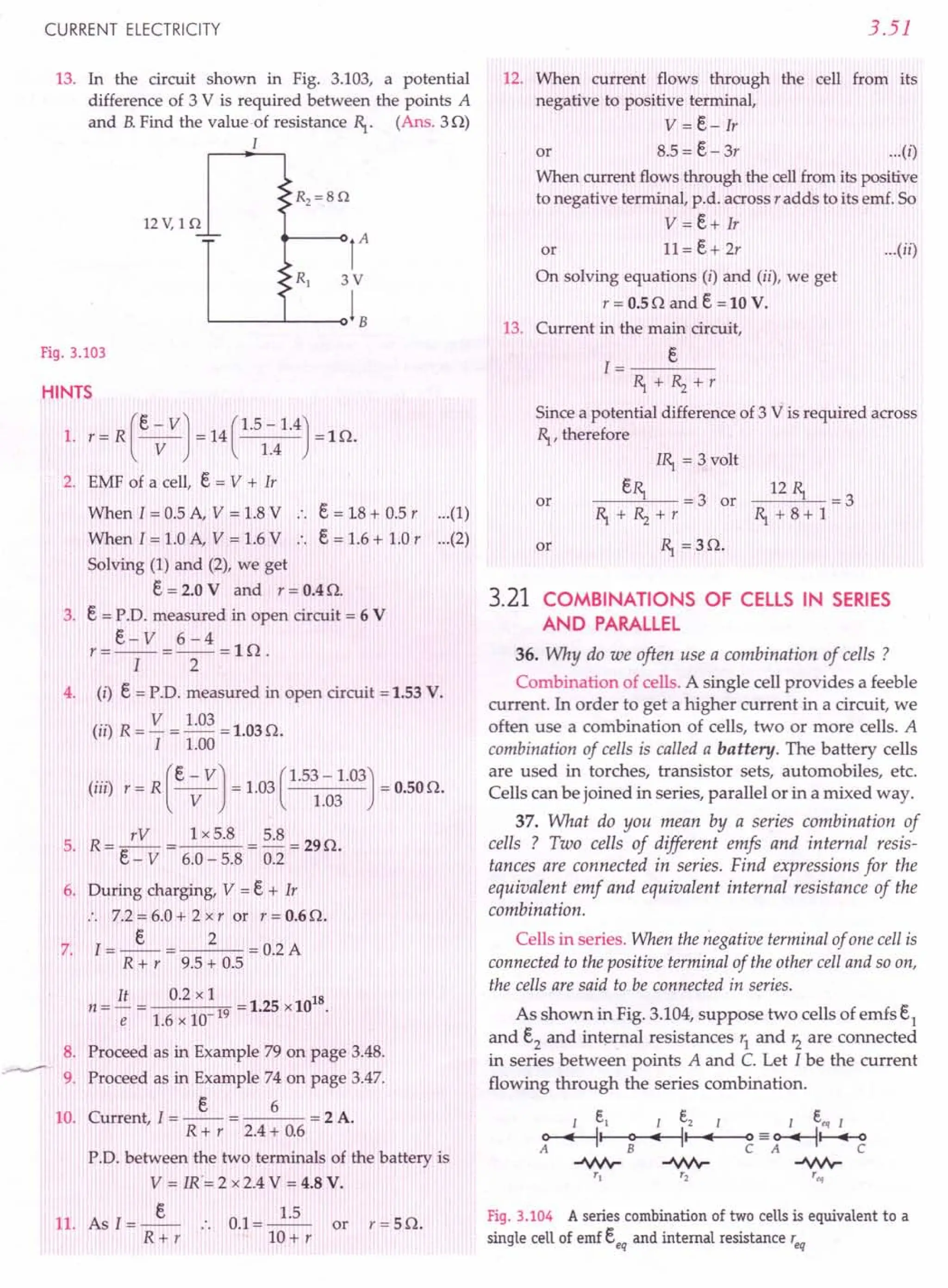
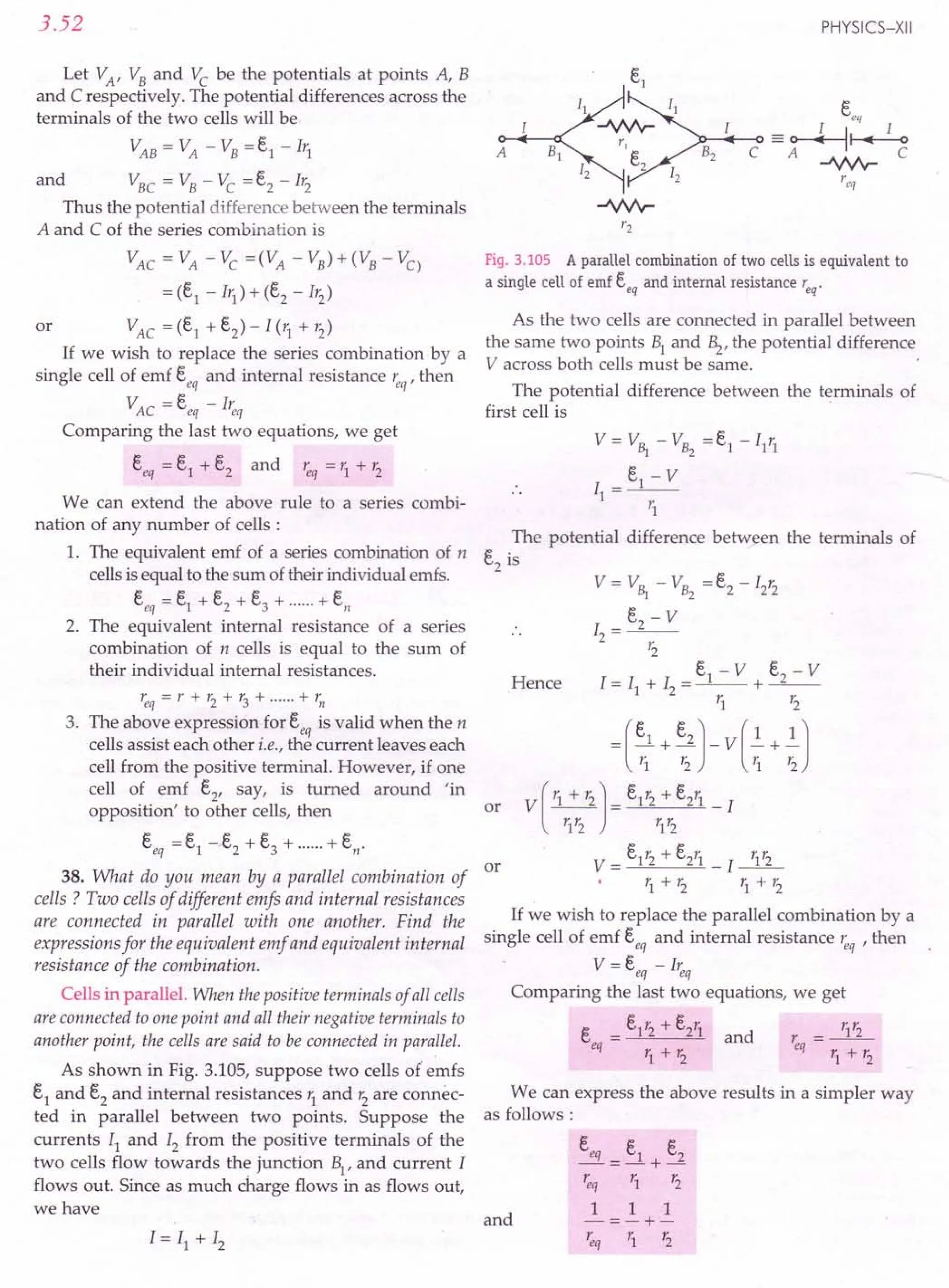
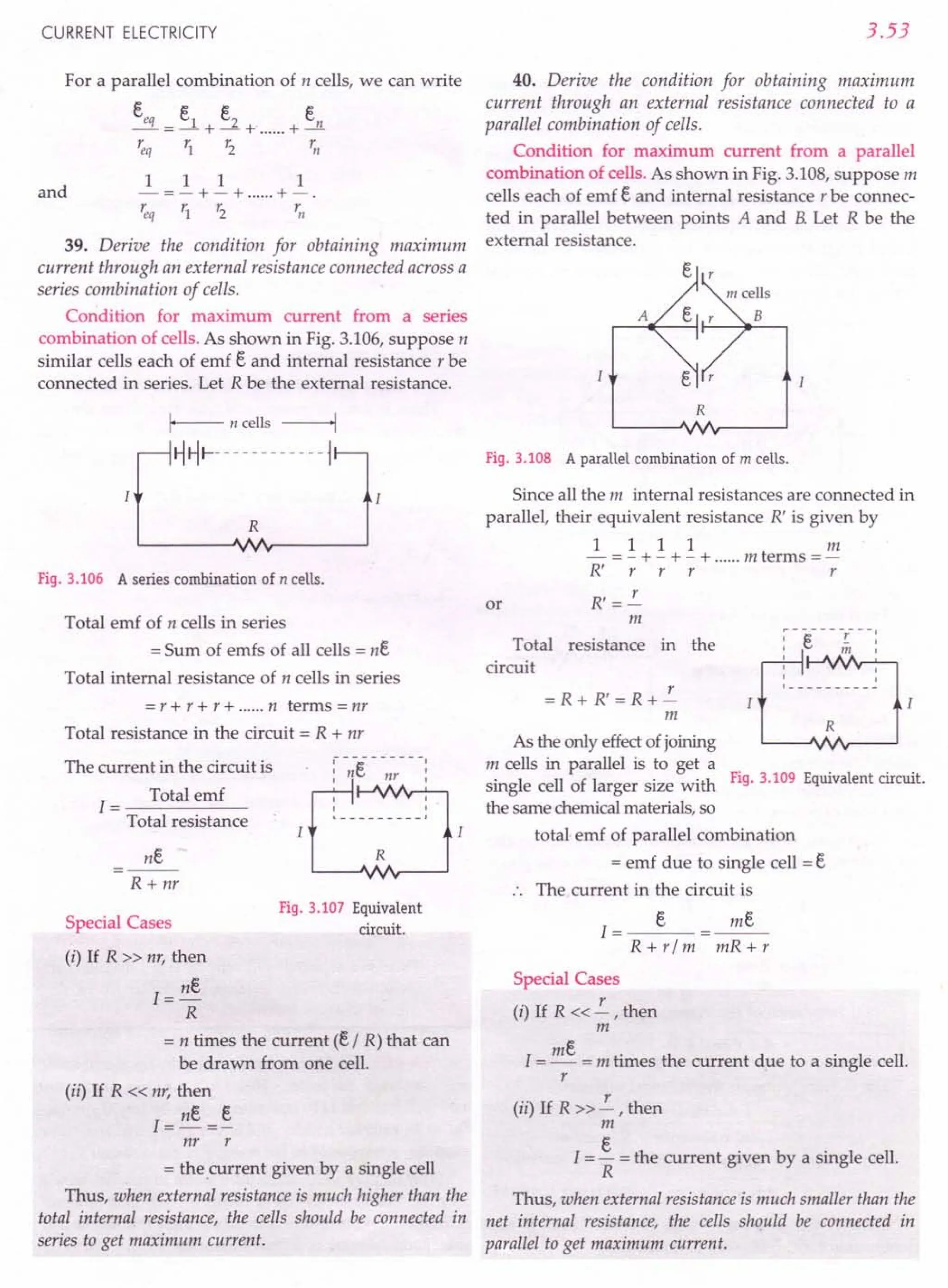
![3.54
41. Derive the condition for obtaining maximum
current through an external resistance connected across a
mixed grouping of cells.
Mixed grouping of cells. In this combination, a certain
number of identical cells are joined in series, and all such
rows are then connected in parallel with each other.
As shown in Fig. 3.110, suppose n cells, each of emf
e and internal resistance r, are connected in series in
each row and m such rows are connected in parallel
across the external resistance R.
A,:-.q:-- m rows ~...;;,
I~I------------~
I~I------------~
R
Fig.3.110 Mixed grouping of ceUs.
Total number of cells
=mn
Net emf of each row of n
cells in series = ne
As m such rows are
connected in parallel, so net
emf of the combination = ne
R
Fig. 3.111 Equivalent circuit.
Net internal resistance of
each row of n cells = nr
As m such rows are connected in parallel, so the
total internal resistance t' of the combination is given
by
1 1 11m
- =- + - + - + m terms =-
r nr nr nr nr
or r = nr
m
Total resistance of the circuit
=R+r=R+nr
m
The current through the external resistance R,
1= Total emf ne
Total resistance R + nr / m
mne
mR+ nr
Clearly, the current I will be maximum if the
denominator i.e., (mR + nr) is minimum.
PHYSICS-XII
Now
mR + nr = (.Jri1R)2 + (.Jnr)2
= (.Jri1R)2 + (.Jnr)2 - 2 .Jri1R .Jnr + 2.j mR .Jnr
= (.Jri1R - .Jnr)2 + z.J mnRr
As the perfect square cannot be negative, so
mR + nr will be minimum if
i.e., .jmR -.Jnr = 0
or mR=nr
R = nr
m
or
or External resistance
= Total internal resistance of the cells.
Thus, in a mixed grouping of cells, the current through
the external resistance will be maximum if the external
resistance is equal to the total internal resistance of the cells.
Examples based on
0-- -_ •.. Grouping of Cells
Formulae Used
ne
1=--
R+ nr
ne
2. For n cells in parallel, I = --
nR+ r
1. For n cells in series,
mne
3. For mixed grouping, I = ---
mR+ nr
where n = no. of cells in series in one row,
m = no. of rows of cells in parallel.
4. For maximum current, the external resistance
must be equal to the total internal resistance.
i.e., nT = R
m
or nr = mR
Units Used
EMF and terminal p.d. are in volt (V), internal
resistance (r) and external resistance R in Q,
current in ampere (A).
Example 87. (a) Three cells of emf2.0 V, 1.8 V and 1.5 V
are connected in series. Their internal resistances are
0.0512,0.712 and In respectively. If the battery is connec-
ted to an external resistor of 412 via a very low resistance
ammeter, what would be the reading in the ammeter ?
(b) If the three cells above were joined in parallel, would
they be characterised by a definite emf and internal
resistance (independent of external circuit) ? If not, how will
you obtain currents in different branches? [NCERT]](https://image.slidesharecdn.com/slaroraclass12thphysicsbyrockytrickster-250318042948-c8b51a5a/75/SL-ARORA-CLASS-12TH-PHYSICS-BY-ROCKY-TRICKSTER-pdf-239-2048.jpg)
![CURRENT ELECTRICITY
Solution. (a) The circuit diagram is shown in
Fig. 3.112.
I
r----------, ~---------I r----------,
0.05 Q I: 0.7 Q I: 1 Q
I ~~I-'VJ'r-"""""
~
~
-~
------: ~
!.~
y- - - - - -: ~!.§-~ - - - --
Fig. 3.112
3.55
Resistance of external circuit = Total resistance of
two resistances of 17 n connected in parallel
or R = Rl~ = 17x 17 n =8.5n
Rl + ~ 17 + 17
17Q
As the three cells have been connected in series to
an external resistor of 4 n, therefore
Total emf = (2.0 + 1.8 + 1.5) V = 5.3 V Fig. 3.113
Total resistance
Current,
= (0.05 + 0.7 + 1 + 4) n = 5.75 n
1= emf
resistance
= 5.3 A=O.92A.
5.75
(b) No, there is no formula for emf and internal
resistance of non-similar cells, joined in parallel. For
this situation, we must use Kirchhoff's laws.
Example 88. A cell of emf 1.1 V and internal resistance
or
0.5 n is connected to a wire of resistance 0.5 n. Another cell
of the same emf is connected in series but the current in the
wire remains the same. Find the internal resistance of the
second cell.
Solution. In first case:
Total emf, Eo = 1.1 V
Total resistance, R = 0.5 + 0.5 = 1n
:. Current, I=! = 1.1 = 1.1 A
R 1
In second case :
Total emf,
Eo == 1.1 + 1.1 =2.2 V
Total resistance,
R = 0.5 + 0.5 + r = (1 + r) n
where r is the internal resistance of the second cell.
C
2.2
urrent, 1=--=1.1 or r=ln.
l+r
Example 89. Two identical cells of emf 1.5 Veach joined
in parallel provide supply to an external circuit consisting of
two resistances of17 n each joined in parallel. A very high
resistance voltmeter reads the terminal voltage of cells to be
1.4 V. Calculate the internal resistance of each cell.
[eBSE 0 9SC]
Solution. Here Eo =1.5 V, V =1.4 V
Let l' be the total internal resistance of the two cells.
Then
As the two cells of internal resistance r neach have
been connected in parallel, therefore.
1 1 1 1 2
-=-+- or -=-
l' r r 0.6 r
r = 0.6 x 2 = 1.2 n.
Example 90. Four identical cells, each of emf 2 V, are
joined in parallel providing supply of current to external
circuit consisting of two 15 n resistors joined in parallel.
The terminal voltage of the cells, as read by an ideal
voltmeter is 1.6 volt. Calculate the internal resistance of each
cell. [CBSE 0 02]
Solution. As shown in Fig. 3.114, four cell are
connected in parallel to the parallel combination of two
15 n resistors.
lSQ
Fig. 3.114
Here Eo =2 V, V =1.6 V
The external resistance provided. by two 15 n
resistors connected in parallel is
15 xIS
R=--=7.5n
15 + 15](https://image.slidesharecdn.com/slaroraclass12thphysicsbyrockytrickster-250318042948-c8b51a5a/75/SL-ARORA-CLASS-12TH-PHYSICS-BY-ROCKY-TRICKSTER-pdf-240-2048.jpg)
![3.56
If r' is the total internal resistance of the four cells
connected in parallel, then
l' = R (e - VJ =7.5 (2 -1.6) = 15 n
V 1.6 8
If r is the internal resistance of each cell, then
1 1 1 1 1 4
-=-+-+-+-=-
l' r r r r r
15
or r = 41' = 4 x - = 7.5 n.
8
Example 91. In the circuit
diagram given in Fig. 3.115,
the cells £1 and £2 have emfs
4 V and 8 V and internal
resistances 0.5 n and 1.0 n
respectively. Calculate' the
current in each resistance.
4.50
60
[CBSE DISC]
Fig. 3.115
Solution. Effective emf of the circuit
= e2 - e1 =8 - 4 = 4 V
Total resistance of the circuit
3x6
= 1 + 0.5 + 4.5 n + -- = 8 n
3+6
:. Current in the circuit, I = ~ = 0.5 A
Current through 4.5 n resistance = I = 0.5 A
p.o. across the parallel combination of 3 nand 6 n
resistances is
3x6
V = R'I = -- x 0.5 = 1 V
3+6
Current through 3 n resistance =~=!A
3n 3
=~=!A.
s o 6
Current through 6 n resistance
Example 92. In Fig. 3.116, e1 and e2 are respectively
2.0 V and 4.0 V and the resistances r1, r2 and Rare
respectively 1.0 n, 2.0 nand 5.0 n. Calculate the current in
the circuit. Also calculate (i) potential difference between the
points b and a, (ii) potential difference between a and c.
:------e---: :-e-------:
c I lL~ 2 I b
I ~ I
: Y1 :: Y2:
---------- ----------
R
Fig. 3.116
Solution. As emfs e1 and e2 are opposing each
other and e2 > e1, so
Netemf=e2 -e1 =4-2 =2 V.
PHYSICS-XII
This emf sends circuit I in the anti clockwise
direction.
Total resistance = R + r1 + r2 = 5 + 1 + 2 = 8 n
Current in the circuit
Net emf 2
----- = - = 0.25 A.
Total resistance 8
(i) Current inside the cell e2
flows from -ve to +ve
terminal, so the terminal p.d. of this cell is
Va - Vb = e2 - Ir2
= 4.0 -0.25 x 2.0 = 3.5 V.
(ii) Current inside the cell e1
flows from +ve to -ve
terminal. Hence the terminal p.d. of this cell is
Va - Vc = e1 + Ir1
=2.0 + 0.25 x 1.0 = 2.25 V.
Example 93. In the two electric circuits shown in
Fig. 3.117, determine the readings of ideal ammeter (A) and
the ideal voltmeter (V). [CBSE DISC]
Fig. 3.117 (a) (b)
Solution. In the circuit (a)
Total emf = 15 V, Total resistance =2n
15V
Current, 1=-- = 7.5 A
2n
As the current I flows from -ve to +ve terminal
inside the cell of 6 V, the terminal p.d. of the cells is
V = e-Ir=6-7.5x 1 =-1.5 V
:. Reading of ammeter = 7.5 A,
Reading of voltmeter = -1.5 V.
In the circuit (b)
Net emf =9-6 =3V, Total resistance =2n
3V
Current, I = - = 1.5 A
2n
As the current I flows from +ve to -ve terminal
inside the 6 V cell, so the terminal p.d. of the cell is
V = e + Ir = 6 + 1.5 x 1 = 7.5 V
Reading of ammeter = 1.5 A,
Reading of voltmeter = 7.5 V.](https://image.slidesharecdn.com/slaroraclass12thphysicsbyrockytrickster-250318042948-c8b51a5a/75/SL-ARORA-CLASS-12TH-PHYSICS-BY-ROCKY-TRICKSTER-pdf-241-2048.jpg)
![CURRENT ELECTRICITY
Example 94. A network of resistances is connected to a
16 V battery with internal resistance of 10, as shown in
Fig. 3.118.
(a) Compute equivalent resistance of the network,
(b) Obtain the current in each resistor, and
(c) Obtain the voltage drops VAB
, VBC
and Vco'
[NCERT ; CBSE F 10]
40 120
I 10
B
16 V
r---------.
, 10'
, ,
,
,
1 --_ ••
Fig. 3.118
Solution. (a) As the two 4 0 resistances are in
parallel, their equivalent resistance is
R=4x4=20
1 4 + 4
..
Also, the 12 0 and 60 resistances are in parallel,
their equivalent resistance is
~ = 12 x 6 =40
12 + 6
Now the resistances R1
, ~ and 10 are in series.
Hence the equivalent resistance of the network is
R = Rl + ~ + 1 =2 + 4 + 1 = 70.
(b) The total current in the circuit is
I=_e_=~=2A
R+r 7+1
or
The potential difference between A and B is
VAB = 4 II = 4 12
II = 12
But II + 12= 1=2 A
II = 12= 1 A
The potential difference between C and D is
Vco = 12 13 = 6 14 i.e., 14 = 213
But 13 + 14 = I =2 A
13 + 213 =2 A
2
13="3A and
4
14=-A
3
(c) VAB
= 4 x II = 4 x 1 = 4 V,
VBC
= 1 x' I = 1 x 2 = 2 V,
2
Vco = 12 x 13= 12 x 3" = 8 V.
3.57
Example 95. A 20 V battery of internal resistance 10 is
connected to three coils of 12 0,6 0 and 4 0 in parallel, a
resistor of5 0 and a reversed battery (emf = 8 V and internal
resistance =2 0), as shown in Fig. 3.119. Calculate the
current in each resistor and the terminal potential difference
across each battery. [CBSE 00 OlC]
10 20V
~---------I
r--l __ -!:--'.fV'v~ 111-+:-"---'
50 c:
N
,....;
8V, 20
.-- - - - - - - - ~
: 1II---JV'Ifr-L' ----..------'
Fig. 3.119
Solution. Equivalent resistance R' of 12 0,60,40
resistances connected in parallel is given by
1 1 1 1 6 1
-=-+-+-=-=-
R' 12 6 4 12 2
R'=20
or
Total resistance = 1 + 5 + 2 + 2 = 10 0
Net emf =20 -8 =12
Current in the circuit, 1= 12 = 1.2 A
10
So the current through each battery and 5 0 resistor
is 1.2 A.
P.D. across the parallel combination of three
resistors is
V' = IR' =1.2 x 2 =2.4 V
Current in 2 0 coil = 2.4 = 0.2 A
12
Current in 6 0 coil = 2.4 = 0.4 A
6
Current in 4 0 coil = 2.4 = 0.6 A.
4
Terminal p.d. across 20 V battery,
V = e- Ir = 20 -1.2 x 1 = 18.8 V
Terminal p.d. across 8 V battery,
V' = e' + l r =8 + 1.2 x 2 = 10.4 V.
Example 96.36 cells each of internal resistance 0.5 0 and
emfl.5 Veach are used to send current through an external
circuit of 2 0 resistance. Find the best mode of grouping
them and the current through the external circuit.
Solution. Here e = 1.5 V, r = 0.5 0, R = 2 0
Total number of cells, mn = 36 ...(1)](https://image.slidesharecdn.com/slaroraclass12thphysicsbyrockytrickster-250318042948-c8b51a5a/75/SL-ARORA-CLASS-12TH-PHYSICS-BY-ROCKY-TRICKSTER-pdf-242-2048.jpg)
![3.58
For maximum current in the mixed grouping,
nr = R or n x 0.5 = 2 .... (2)
m m
Multiplying equations (1) and (2), we get
0.5n2=72 or n2=i44
n = 12 and m = 36 =3
12
Thus for maximum current there should be three
rows in parallel, each containing 12 cells in series.
:. Maximum current
mne 36 x 1.5 = 4.0 A.
mR + nr 3 x 2 + 12 x 0.5
Example 97. 12 cells, each of emf 1.5 V and internal
resistance of 0.5 0, are arranged in m rows each containing
n cells connected in series, as shown. Calculate the values of
nand mfor which this combination would send maximum
current through an external resistance of1.5 O.
[CBSE
SamplePaper08]
~R=1.5n~
~~'----~~i
i 1
1 1
1 - - _ - - - - - - - - - - - - ~ m rows
1 I'
1 1
~ - - - -1111- - - -11- - - - _I
(n cellsin eachrow)
Fig. 3.120
Solution. For maximum current through the
external resistance,
External resistance
= Total internal resistance of the cells
R = nr
m
1.5 = n ~~.5 [mn = 12]
or
n
or 36 = n2
or n = 6 and m = 2.
Example 98. In the given circuit in the steady state, obtain
the expressions for (i) the potential drop (ii) the charge and
(iii) the energy stored in the capacitor, C [CBSE
F 15]
V R
F
PHYSICS-XII
Solution. In the steady state (when the capacitor is
fully charged), no current flows through the branch BE.
Net emf =2 V - V = V
Net resistance =2 R + R =3R
C . h . . I V
:. urrent In t e CIrCUIt, =-
3R
Potential difference across BE
V 4
=2V -Ix2R =2V --x2R =- V
3R 3
(i) Potential difference across C = ±V - V = V .
3 3
(ii) Charge on the capacitor, Q = Cx V = CV .
3 3
(iii) Energy stored in the capacitor
= ~C(V)2 CV
2
2 3 18
~roblem5 For Practice
1. Three identical cells, each of emf 2 V and internal
resistance 0.2 n are connected in series to an
external resistor of 7.4 n. Calculate the current in
the circuit. (Ans. 0.75 A)
2. Three identical cells each of emf 2 V and unknown
internal resistance are connected in parallel. This
combination is connected to a 5 n resistor. If the
terminal voltage across the cells is 1.5V, what is the
internal resistance of each cell? [CBSEOD 99]
(Ans.5n)
3. Two cells connected in series have electromotive
force of 1.5 Veach. Their internal resistances are
0.5nand 0.25n respectively. This combination is
connected to a resistance of 2.25n. Calculate the
current flowing in the circuit and the potential
difference across the terminals of each cell.
(Ans. 1.0 A, 1.0 V, 1.25V)
4. When 10 cells in series are connected to the ends of
a resistance of 59n, the current is found to be
0.25 A, but when the same cells after being
connected in parallel are joined to the ends of a
0.05n, the current is 25 A. Calculate the internal
resistance and emf of each cell. (Ans. O.ln, 1.5V)
5. Find the minimum number of cells required to
produce an electric current of 1.5 A through a
resistance of 30n. Given that the emf of each cell is
1.5 V and internal resistance 10o.
(Ans. 120 cells, 60 cells in one row
and two rows in parallel)
Two identical cells,whether joined together in series
or in parallel give the same current, when connec-
ted to an external resistance of 1 n. Find the inter-
nal resistance of each cell. [ISCE95] (Ans. 1n)
A
V C
B
~ E
6.
2V 2R
C 0
Fig. 3.121](https://image.slidesharecdn.com/slaroraclass12thphysicsbyrockytrickster-250318042948-c8b51a5a/75/SL-ARORA-CLASS-12TH-PHYSICS-BY-ROCKY-TRICKSTER-pdf-243-2048.jpg)
![CURRENT ELECTRICITY
7. A set of 4 cells, each of emf 2 V and internal resis-
tance 1.5n are connected across an external load of
10n with 2 rows, 2 cells in each branch. Calculate
the current in each branch and potential difference
across 10n. [Karnataka 91C]
(Ans. 0.175 A, 3.5 V)
HINTS
nE. 3 x 2 6
1. 1=--= =-=0.75A.
R + nr 7.4 + 3 x 0.2 8
2. Here E. = 2V, V = 1.5 V, R = 5 n
If r' is the total internal resistance of the three cells
connected in parallel, then
r' = R [E. - V] = 5 [2 - 1.5] = ~ n
V 1.5 3
1 1 1 1 3 3
But - = - + - + - or - = - .. r = 5 n.
r' r r r 5 r
3. Total resistance, R = 0.5 + 0.25 + 2.25 = 3.0n
Total emf, E. = 1.5 + 1.5 = 3.0 V
C . h . . 1 E 3.0 lOA
urrent m t e circuit, = - = - = .
R 3.0
P.D. across first cell,
VI = E - bi = 1.5 - 1.0 x 0.5 = 1.0 V
P.D. across second cell,
V2
= E - 1r2 = 1.5 - 1.0 x 0.25 = 1.25 V.
4. For series combination. The current is
lOE
---=0.25A
59
+ 10
r
For parallel combination. The current is
lOE
----=25A
10 x 0.05 + r
On solving the above two equations,
r = 0.1 nand E = 1.5 V.
nr n x 1
5. As-= R :. --=30 or 1I=30m
m m
nE. n x 1.5
I = - or 1.5 = -- or n = 60
2R 2 x30
. . m = 60/ 30 = 2 and mn = 120.
6. When the cells are connected in series, (Fig. 3.122),
the current in the circuit is
I=~
5 1+ 2r
e
, e
I
Is
Is
R=lQ
-JVVv-
r .
Fig. 3.122
When the cells are
connected in
parallel (Fig. 3.123),
the current in the
circuit is
3.59
s
-JVVv-
re
Ip i,
.J.Nr
r
R=lQ
I =_--::e_
P r x r
1+--
r + r
2E.
2+ r
Fig. 3.123
Given '.>', .. 1+2r 2+r
or 1+ 2r = 2 + r or r = 1 n.
7. The circuit diagram is shown below.
-JVVv-
r
e,
R=lOQ
Fig. 3.124
Here e = 2 V, r = 15 n, R = 10n, 11 = 2, m = 2
ne 2 x2 4
1=--= =-=0.35A.
R
nr 2 x 1.5 11.5
+- 10+--
m 2
The two branches are identical.
:. Current in each branch = 0.35 = 0.175 A.
2
Potential difference across R
= IR = 0.35 x 10 = 3.5 V.
3.22 HEATING EFFECT OF CURRENT
42. What is heating effect of current ? Explain the
cause of heating effect of current.
Heating effect of current. Consider a purely
resistive circuit i.e., a circuit which consists of only
some resistors and a source of emf. The energy of the
source gets dissipated entirely in the form of heat
produced in the resistors. The phenomenon of the produc-
tion of heat in a resistor by the flow of an electric current
through it is called heating effect of current orJoule heating.
Cause of heating effect of current. When a potential
difference is applied across the ends of a conductor, its
free electrons get accelerated in the opposite direction
of the applied field. But the speed of the electrons does
not increase beyond a constant drift speed. This is](https://image.slidesharecdn.com/slaroraclass12thphysicsbyrockytrickster-250318042948-c8b51a5a/75/SL-ARORA-CLASS-12TH-PHYSICS-BY-ROCKY-TRICKSTER-pdf-244-2048.jpg)
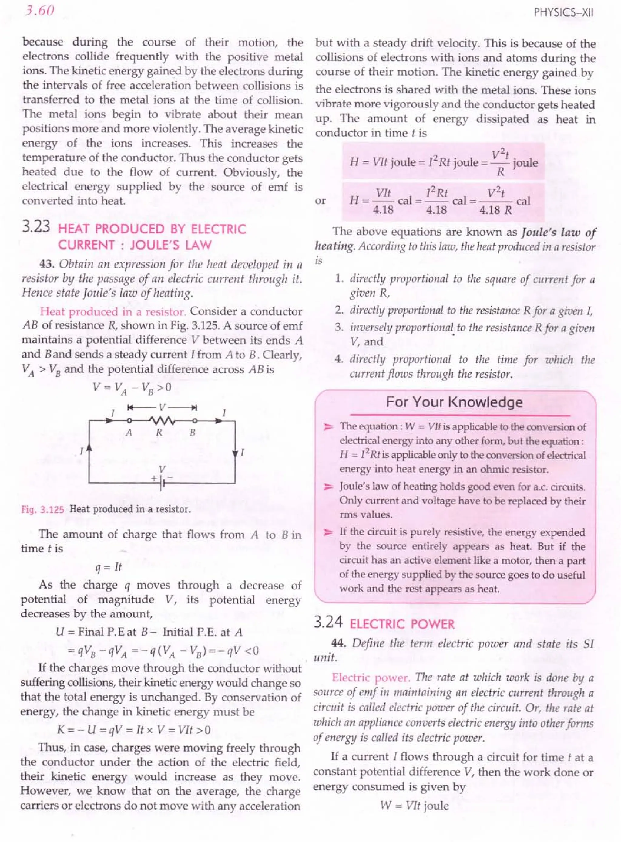
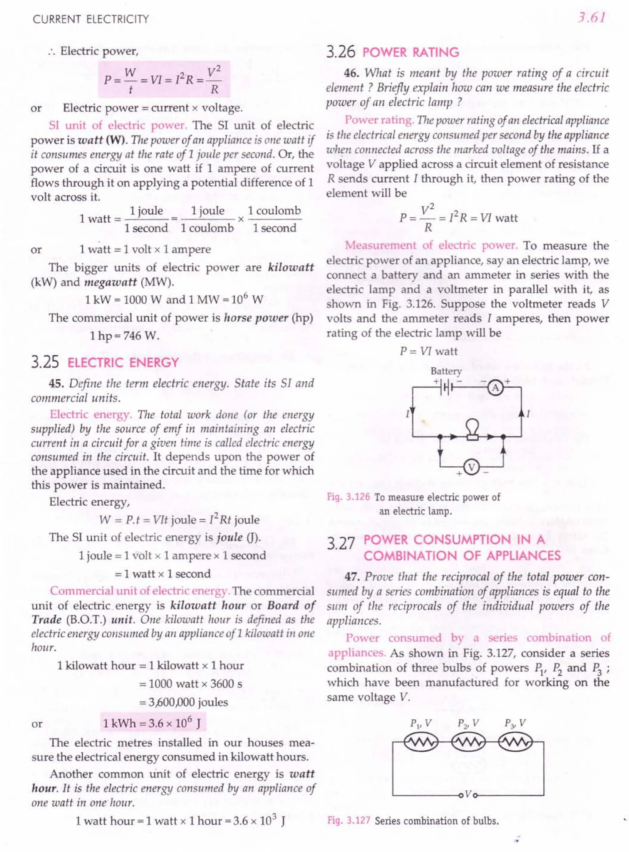
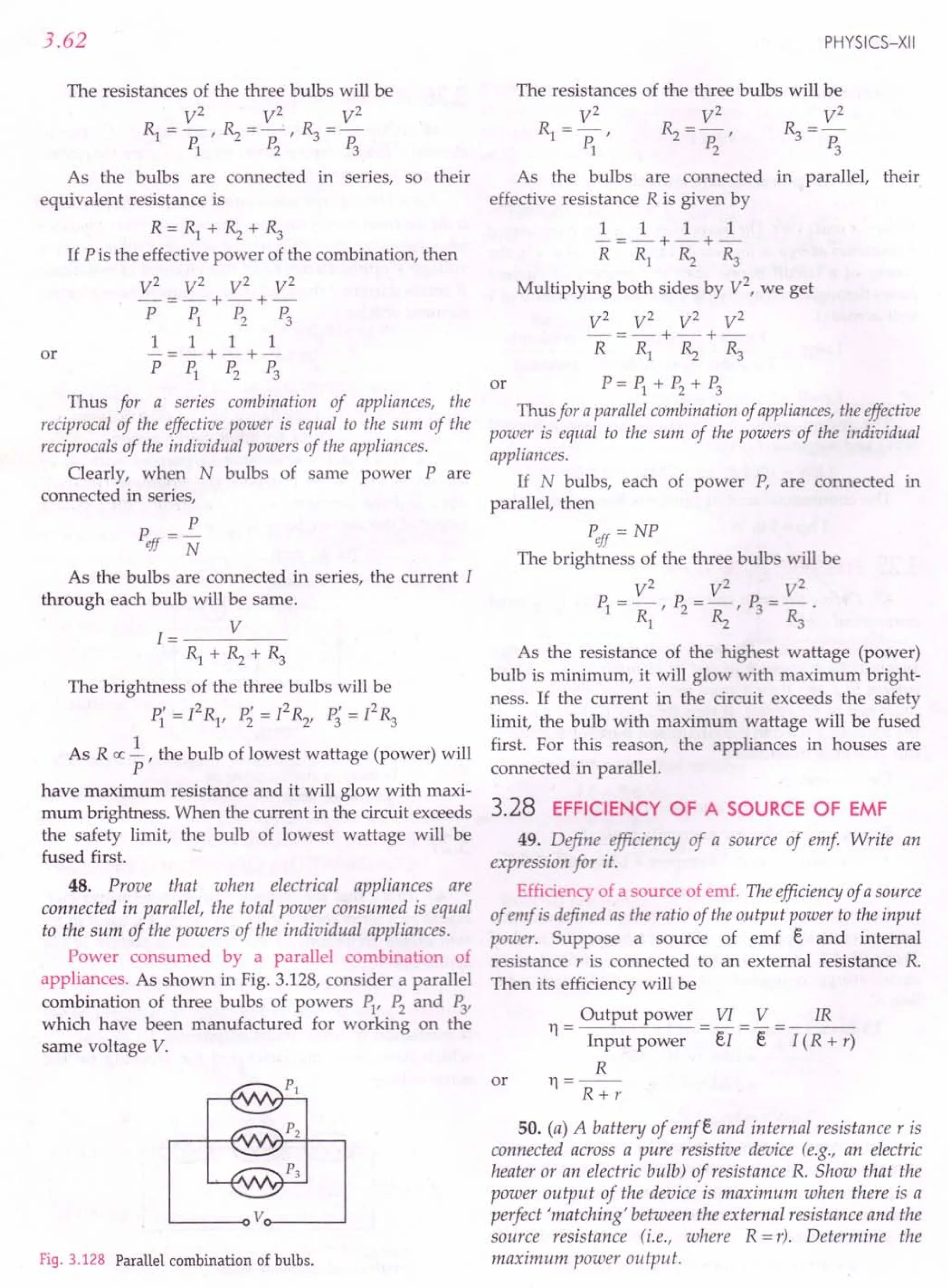
![CURRENT ELECTRICITY
(b) What is power output of the source above if the
battery is shorted ? What is the power dissipation inside
the battery in that case ? [NCERT)
Maximum power theorem. it states that the output
power of a source of emf is maximum when the external
resistance in the circuit is equal to the internal resistance of
the source.
Let emf of the battery
Internal resistance
Resistance of the device
=r
=R
.'. Current through the
device,
Total emf
1=-----
Total resistance
R+r Fig. 3.129
.'. Power output of the resistive device will be
P = I 2R =(_e_J2 R
R+r
e2
R e2
R
(R+r)2 (R-r)2+4Rr
Obviously, the power output will be maximum
when
R - r = 0 or R = r
Thus, the power output of the device is maximum
when there is a perfect matching between the external
resistance and the resistance of the source, i.e., when
R = r. This proves maximum power theorem.
Maximum power output of the source is
Pmax =~= e
2
[Putting R=rin Eq. (i)]
(r + r) 4 r
(b) When the battery is shorted, R becomes zero,
therefore, power output = O. In this case, entire power
of the battery is dissipated as heat inside the battery
due to its internal resistance.
Power dissipation inside the battery
= I
2
r = (~r
r = er
2
.
51. Show that the efficiency of a battery when
delivering maximum power is only 50%.
Maximum efficiency of a source of emf. For a
source of emf,
Input power = eI
Output power = VI
3.63
.'. Efficiency
VI V IR R
11=-=-= =--
eI e I( R + r) R + r
When the source delivers maximum power, R = r
r 1
. . 11= -- = - = 50%
r;+- r 2
Thus the efficiency of a source of emf is just 50%
when it is delivering maximum power.
3.29 EFFICIENCY OF AN ELECTRIC DEVICE
52. Define efficiency of an electric device. Write an
expression for the efficiency of an electric motor.
Efficiency of an electric device. The efficienClJof an
electric device is defined as the ratio of the output power to
the input power
Output power
11= --"---"---
Input power
For an electric motor, we can write
···(0
Output mechanical power
11= --"--------=---
Input electric power
Here, input electrical power
= Output mechanical power + Power lost as heat
53. (a) An electric motor runs on a d.c. source of emfe
and internal resistance r. Show that the power output of
the source is maximum when the current drawn by the
motor is e/2r.
(b) Show that power output of electricmotor is maximum
when the back emf is one-half the source emf provided the
resistance of the windings of the motor is negligible.
(c) Compare and contrast carefully the situation in this
exercise with that in Q.SO(a) above. [NCERT)
(a) Output power from a source connected to an
electric motor. Let the current drawn by the motor be I.
Then
Power output of the source, P = eI - I2
r
P· . h dP 0
IS maxImum w en - =
dI
e - 2 Ir = 0 or I = ~
2r
or
Hence the power output of the source is maximum when
the current drawn by the motor is e/2 r.
(b) Here, emf of source = e
Internal resistance of source = r
Back emf of motor = e'
Resistance of motor =R"'O
As the external resistance R is negligible, therefore
. th . . e-e'
current ill e circuit = -- .
r](https://image.slidesharecdn.com/slaroraclass12thphysicsbyrockytrickster-250318042948-c8b51a5a/75/SL-ARORA-CLASS-12TH-PHYSICS-BY-ROCKY-TRICKSTER-pdf-248-2048.jpg)
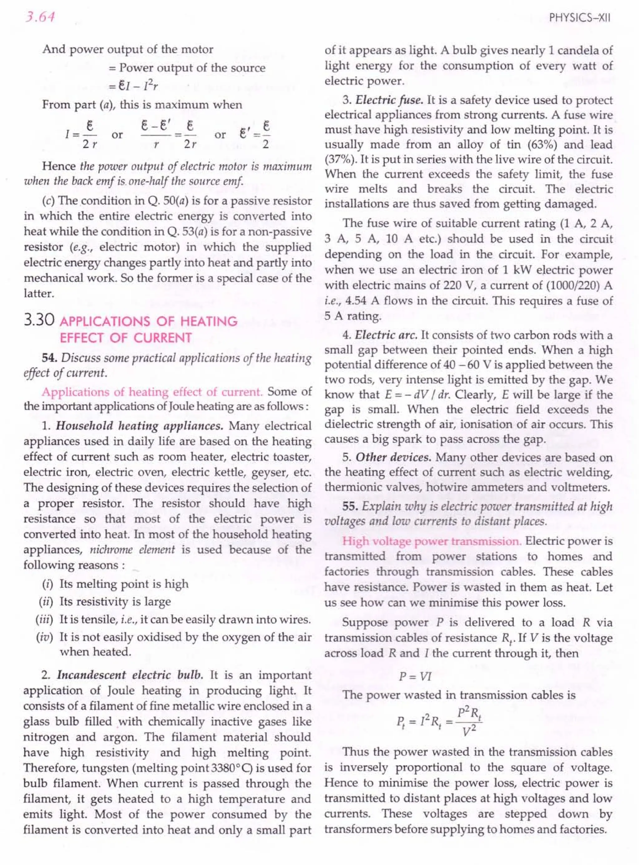
![CURRENT ELECTRICITY
For Your Knowledge
~ The emission of light by a substance when heated to a
high temperature is called incandescence.
~ A heater wire is made from a material of large resis-
tivity and high melting point while a fuse wire is made
from a material of large resistivity and low melting point
~ The load in an electric circuit refers to the current
drawn by the circuit from the supply line. If the
current in a circuit exceeds the safe value, we say that
the circuit is overloaded.
~ The temperature upto which a wire gets heated (i.e.,
steady state temperature 9) is directly proportional to
the square of the current and is inversely proportional
to the cube of its radius but is independent of its length.
]2
9ex:-
r3
~ When the resistances are connected in series, the I
current] through each resistance is same. Consequently,
Pex:R (':P=12R)
and V ex: R (.: ~ = ]R)
Hence in a series combination of resistances, the
potential difference, power consumed and hence heat
produced will be larger in the higher resistance.
~ When the resistances are connected in parallel, the
potential difference V is same across each resistance.
Consequently,
1
Pex: -
R
and
1
I ex: -
R
Hence in a parallel combination of resistances, the
current, power consumed and hence heat produced
will be larger in the smaller resistance.
~,--------------~
Formulae Used
1. Heat produced by electric current,
12Rt
H = f Rt joule = -- cal
4.18
or H = VIt joule = VIt cal
4.18
W V
2
2. Electric power, P = - = VI = 12R = -
t R
3. Electric energy, W = Pt = VIt = /2 Rt
Units Used
Current I is in ampere, resistance R in ohm, time t
in second, power P in watt, electric energy in joule
or in kWh.
3.65
Example 99. An electric current of 4.0 Aflows through a
12 0 resistor. What is the rate at which heat energy is
produced in the resistor? [NCERT]
Solution. Here I = 4 A, R = 12 0
Rate of production of heat energy,
P = I2
R =42
x 12 =192 W.
Example 100. How many electrons flow through the
filament of a 120 V and 60 W electric lamp per second ?
Given e = 1.6 x 10- 19 C.
Solution. Here P =60 W, V =120 V, t =1 s
1= P =~=O.5A
V 120
But I=!1. = ne
t t
No. of electrons flowing per second is
It 0.5 x 1 18
n = - = 19 = 3.125 x 10 .
e 1.6xlO-
Example 101. A heating element is marked 210 V,630 W.
What is the current drawn by the element when connected to
a 210 V d.c. mains? What is the resistance of the element?
[NCERT]
Solution. Here P =630 W, V =210 V
P 630
Current drawn 1=- = - = 3 A.
, V 210
. V 210
Resistance of the element, R = - = - = 70 O.
I 3
Example 102. A 10 V storage battery of negligible internal
resistance is connected across a 500 resistor made of alloy
manganin. How much heat energy is produced in the resistor
in 1 h ? What 'is the source of this energy ? [NCERT]
Solution. Here V = 10 V, R = 50 0, t = 1 h = 3600 s
Heat energy produced in 1h is
H = V
2
t = 10 x 10 x 3600 = 7200 J.
R 50
The source of this energy is the chemical energy
stored in the battery.
Example 103. An electric motor operates on a 50 V supply
and draws a current of 12 A If the motor yields a mecha-
nical power of 150 W, what is the percentage efficiency of the
motor ? [NCERT]
Solution. Input power =VI = 50 x 12 =600 W
Output power = 150 W
Efficiency of motor
= Output power x 100 = 150 x 100
Input power 600
=25%.](https://image.slidesharecdn.com/slaroraclass12thphysicsbyrockytrickster-250318042948-c8b51a5a/75/SL-ARORA-CLASS-12TH-PHYSICS-BY-ROCKY-TRICKSTER-pdf-250-2048.jpg)
![3.66
Example 104. An electric motor operating on a 50 V d.c.
supply draws a current of12 A. If the efficiency of the motor
is30%, estimate the resistance of the windings of the motor.
[NCERT]
Solution. Here V = 50 V, I = 12 A, Yl = 30%
As the efficiency of electric motor is 30%, therefore,
power dissipated as heat is
70
P = 70% of VI = - x 50 x 12 W = 420 W
100
But power dissipated as heat, P = [2R
PR = 420
R = 420 = 420 = 2.9 O.
12 144
or
Example 105. (a) A nichrome heating element across
230 V supply consumes 1.5 kW of power and heats up to a
temperature of 7500
C.A tungsten bulb across the same supply
operates at a much higher temperature of1600°C in order to
be able to emit light. Does it mean that the tungsten bulb
necessarily consumes greater power? (b) Which of the two
has greater resi~J!mce_: a 1kW heater or a ioo tv tungste..n
.bulb, both marked for 230 V ? [NCERT]
Solution. (a) No, the steady temperature acquired
by a resistor depends not only on the power consumed
but also its characteristics such as surface area, emissi-
vity, etc., which determine its power loss due to radiation.
(b) Here V =230 V, PI =1 kW =1000 W, P2
=100 W
R = V
2
= 230 x 230 0 = 52.9 0
1 PI 1000
~ = V
2
=230 x 230 0 =5290
P2
100
Thus the 100 W bulb has a greater resistance.
Example 106. An electric power station (100 MW)
transmits power to a distant load through long and thin
cables. Which of the two modes of transmission would result
in lesser power wastage: power transmission of: (i) 20AJOO
V
or (ii) 200 V ? [ CERT]
Solution. Let R be the resistance of transmission cables.
Here P = 100 MW = 100 x 106
W
(i) VI = 20AJOO
V
P 100 x 106
:. Current, II =- = = 5000 A
VI 20AJOO
Rate of heat dissipation at 20AJOO
V is
PI = IiR =(5000)2 R =25 x 106
R watt.
(ii) V2
= 200 V
. 100 x 106
5
.. Current, 12 = 200 = 5 x 10 A
PHYSICS-XII
Rate of heat dissipation at 200 V is
P2
= I~R = (5 x 10⁵
)2 R =25 x 1010
R watt
Clearly, PI < P2
•
Hence there will be lesser power wastage when the
power is transmitted at 20,000 V.
Example 107. Two ribbons are given with the following
particulars:
Ribbon I
A B
Alloy I Constantan Nichrome
Length (m) 8.456 4.235
Width (mm) 1.0 2.0
Thickness (mm) 0.03 0.06
Temp. coefficient of egligible egligible
resisti vity (OC- 1)
Resistivity (Om) 4.9 x 10⁻⁷
I 1.1 x 10⁻⁶
For afixed voltage supply, which of the two ribbons corres-
ponds to a greater rate of heat production? [ CERT]
Solution. Since R = p i
A
Resistance of constantan ribbon,
R = 4.9 x 10-
7
x 8.456 0 = 138.1 0
1 1.0 x 10-3 x 0.03 x 10-3
Let V be the fixed supply voltage. Then the rate of
production of heat in constantan ribbon,
V2
V2
P, = - =-- watt
1 Rl 138.1
Resistance of nichrome ribbon,
~ = 1.1 x 10-
6
x 4.235 0 =38.80
2.0 x 10-3 x 0.06 x 10-3
Rate of production of heat in nichrome ribbon,
V2
V2
P2
=-=--watt
». 38.8
Clearly nichrome ribbon has greater rate of produc-
tion of heat because of its lesser resistance.
Example 108. A heater coil is rated 100 W,200 V. It is cut
into two identical parts. Both parts are connected together in
parallel, to the same source of200 V. Calculate the energy
liberated per second in the new combination.
[CBSE OD 2000]
Solution. Resistance of heater coil,
R = ~ = 200 x 200 = 400 0
P 100
Resistance of either half part =200 0](https://image.slidesharecdn.com/slaroraclass12thphysicsbyrockytrickster-250318042948-c8b51a5a/75/SL-ARORA-CLASS-12TH-PHYSICS-BY-ROCKY-TRICKSTER-pdf-251-2048.jpg)
![CURRENT ELECTRICITY
Equivalent resistance when both parts are connected
in parallel,
R' = 200 x 200 = 100 Q
200 + 200
Energy liberated per second when combination is
connected to a source of 200 V
V2 200 x 200
=- = =400 J.
R' 100·
Example 109. An electric bulb is marked 100 W,230 V. If
the supply voltage drops to 115 V, what is the heat and light
energy produced by the bulb in 20 min? Calculate the
current flowing through it. [NCERT; CBSE F 94]
Solution. If the resistance of the bulb be R, then
Rate of production of heat and light energy,
V2
P=-
R
R = V
2
= 230 x 230 = 529 Q
P 100
When the voltage drops to V' = 115 V, the total
heat and light energy produced by the bulb in 20 min
will be
V,2
H=Pxt=--xt
R
115 x 115
= x 20 x 60 =30,000 J = 30 kJ.
529
I = V' = 115 = ~ A.
R 529 23
Example 110. An electric bulb rated for 500 W at 100 V is
used in circuit having a 200 V" supply. Calculate the
resistance R that must be put in series with the bulb, so that
the bulb delivers 500 W. [IIT 87]
Solution. Resistance of the bulb,
R = V
2
= 100 x 100 = 20 Q
P 500
Current,
Current through the bulb,
1= V = 100 =5A
R 20
For the same power dissipation, the current
through bulb must be 5 A.
When the bulb is connected to 200 V supply, the
safe resistance of the circuit should be
R' = V' = 200 = 40 Q
I 5
Resistance required to be put in series with the
bulbis
R' - R = 40 - 20 = 20 Q.
3.67
Example 111. The maximum power rating of a 20 Q
resistor is 2.0 kW. (That is, this is the maximum power the
resistor can dissipate (as heat) without melting or changing
in some other undesirable way). Would you connect this
resistor directly across a 300 V d.c. source of negligible
internal resistance? Explain your answer.
[Haryana 97C ; NCERT]
Solution. Maximum power rating of the given 20 Q
resistor,
P' =2.0 kW
When connected to 300 V d.c. supply, the power
consumption or rate of production of heat Would be
P = ~ = 300 x 300 W = 4500 W = 4.5 kW
R 20
This power consumption exceeds the maximum
power rating of the resistor. Hence the 20 Q resistor
must not be connected directly across the 300 V d.c.
source. For doing so, a small resistance of 10 Q should
be connected in series with it.
Example 112. An electric heater and an .electric bulb are
rated 500 W,220 V and 100 W,220 V respectively. Both are
connected in series to a 220 V d.c. mains. Calculate the
power consumed by (i) the heater and (ii) electric bulb.
[CBSE D 97]
Solution. Resistances of heater and bulb are
Rl = V
2
= 220 x 220 = 484 =96.8 Q
PI 500 5
~ = V
2
= 220 x 220 =484Q
P2
100
Total resistance of series combination is
Rl + ~ = 96.8 + 484 = 580.8 Q
Current, I = V = 220 :::0 0.38 A
R 580.8
(i) Power consumed by heater is
PI = PRl =0.382 x 96.8 = 13.8 W.
(ii) Power consumed by bulb,
P2
= P~ =0.382
x 484 = 69.89 w.
Example 113. Two heaters are marked 200 V, 300 Wand
200 V, 600 W. If the heaters are combined in series and the
combination connected to a 200 V d.c. supply, which heater
will produce more heat ? [NCERT]
Solution. Resistances of the two heaters are
R = V
2
= 200 x 200 = 400 Q
IP1
3003
~ = V
2
= 200 x 200 = 200 Q
P2
600 3](https://image.slidesharecdn.com/slaroraclass12thphysicsbyrockytrickster-250318042948-c8b51a5a/75/SL-ARORA-CLASS-12TH-PHYSICS-BY-ROCKY-TRICKSTER-pdf-252-2048.jpg)
![3.68
For series combination,
600
R1 + ~ = 3 = 2000
V 200
:.Current 1=- =- =1 A
, R 200
Power dissipations in the two heaters are
P{ = 12 R1 =12 x 400 = 400 W
3 3
P; = 12 ~ = 12x 200 = 200 W
3 3
.. P{ =2 P;
The first heater (of 300 W) produces more heat than
the second heater.
Example 114. In a part of the circuit shown in the
Fig. 3.130, the rate of heat dissipation in 40 resistor is
100 J / s. Calculate the heat dissipated in the 3 0 resistor in
10 seconds. [CBSE Sample Paper 03]
R, R2
40 20
30
Fig. 3.130
Solution. Let 11be the current through the series
combination of ~ and ~ and 12be the current through
~.
r.o. across (R1 + ~) = r.o. across ~
.. (4 +2) 11=3 12 or 12=211
Rate of heat dissipation in 4 0 resistor
= I~R1 = I~ x 4 =100 Js-1
~100
. . 11= 4 =.J25 = 5 A
and 12=211 =10 A
Heat dissipated in 3 0 resistor in 10 s
= Ii ~t = (10)2 x 3 x 10 = 3000 J.
Example 114. The resistance of each of the three wires,
shown in Fig. 3.131, is 4 O. This combination of resistors is
connected to a source of 4 0
emfe. The ammeter shows 4 0
a reading of 1A Calculate p Q
the power dissipated in the
circuit. e
[CBSE F 03]
Fig. 3.131
PHYSICS-XII
Solution. Total resistance between the points P
and Q,
4x 4
R=--+4=2+4=60
4+4
Current in the circuit, I = 1 A
Power dissipated in the circuit,
P = r2R = 12x 6 = 6 W.
Example 116. A house is fitted with 20 lamps of 60 W
each, 10fans consuming 0.5 A each and an electric kettle of
resistance 110 O. If the energy is supplied at 220 V and costs
75 paise per unit, calculate the monthly bill for running
appliances for 6 hours a day. Take 1 month =30 days.
Solution. Power of 20 lamps of 60 W each
= 20 x 60 = 1200 W
Power consumed by 10 fans at 0.5 A current
= 10 x VI =10 x 220 x 0.5 =1100 W
Power consumed by electric kettle of110 0 resistance
V
2
=220x220 =440W
R 110
Total power of the appliances
= 1200 + 1100 + 440 =2740 W =2.74 kW
Total time for which appliances are used
=6 x 30 =180 h
Total energy consumed
= P. t =2.74 kW x 180 h
= 493.2 kWh or units
.'. Monthly bill = 493.2 x 0.75 = ~369.90.
Example 117. There are two electric bulbs rated 60 W,
110 V and 100 W, 110 V. They are connected in series with a
220 V d.c. supply. Will any bulb fuse? What will happen if
they are connected in-parallel with the same supply?
Solution. Currents required by the two bulbs for
the normal glowness are
I = P1 =~ =0.55 A
1 V 110
and 1 = P2 = 100 =0.91 A
2 V 110
The resistances of the two bulbs are
R = V = 110 = 202 0
1 11 0.55
and ~ = V = 110 =1210
12 0.91
When the bulbs are connected in series across the
220 V supply, the current through each bulb will be
I = V 220 = 0.68 A
R1 + ~ 202 + 121](https://image.slidesharecdn.com/slaroraclass12thphysicsbyrockytrickster-250318042948-c8b51a5a/75/SL-ARORA-CLASS-12TH-PHYSICS-BY-ROCKY-TRICKSTER-pdf-253-2048.jpg)
![CURRENT ELECTRICITY
As II < I and 12> I, so that 60 W bulb will fuse
while the 100 W bulb will light up dim.
When the bulbs are joined in parallel, their
equivalent resistance is
R' = Rl Rz = 202 x 121 =76Q
Rl + Rz 202 + 121
Current drawn from the 220 V supply will be
I' = ~ = 220 :::.
3 A
R' 76
In the two bulbs of resistances Rl (:::.
202 Q) and
Rz (= 120 Q), the current of 3 A will split up into
roughly 1 A and 2 A respectively. Hence both the bulbs
will fuse.
Example 118. The resistance of a 240 V and 200 W
electric bulb when hot is 10 times the resistance when cold.
Find its resistance at room temperature. If the working
temperature of thefilament is 2000°C, find the temperature
coefficient of thefilament.
Solution. Resistance of the hot bulb is given by
R' = ~ = 240 x 240 = 288 Q
P 200
Resistance of bulb at room temperature,
R = !3'.. = ~~ = 28.8 Q
10 10
R'= R(l + at)
288 = 28.8(1 + a x 2000)
- 9 0C-1 _ 4 5 10-3 °C-1
a--- -. x .
2000
Since
or
Example 119. A thin metallic wire of resistance 100 Q is
immersed in a calorimeter containing 250 g of water at 10° C or
and a current of 0.5 ampere is passed through it for half an
hour. If the water equivalent of the calorimeter is 10 g, find
the rise of temperature.
Solution. Here m = 250 g, l = 0.5 A,
t=30min=1800s, w=10g
.'. Heat produced
= [2 Rt = (O.5l x 100 x 1800 J = 45000 J
Heat gained by water and calorimeter
=(m + w) c 9 = (250 + 10) x 1 x 9 cal
=260 x 4.2 9 joule
260 x 4.2 x 9 = 45000
Rise in temperature; 9 = 45000 = 41.2°C.
260 x 4.2
Example 120. A copper electric kettle weighing 1000 g
contains 900 g of water qt 20° e. It takes 12 minutes to raise
the temperature to 100°e. If electric energy is supplied at
210 V, calculate the strength of the current, assuming that or
10% heat is wasted. Specific heat of copper is 0.1.
3.69
Solution. Water equivalent of copper kettle is
w = Mass x Specific heat = 1000 x 0.1 = 100 g
Also m = 900 g,
9 = 02 - 91 =100 -20 =80°C
Heat required,
H = (m + w) c 9 = (900 + 100) x 1 x 80 =80,000 cal
Heat produced
= V I t = 210 x I x 12 x 60 cal =36000 I cal
4.2 4.2
Useful heat
= 90% of 36000 I
= 90 x 36000 [ = 32400 I cal
100
.. 32400 1=80,000
Current, I = 80000 = 2.469 A.
32400
Example 121. A coil of enamelled copper wire of resis-
tance 50 Q is embedded in a block of ice and a potential
difference of 210 V applied across it. Calculate the rate at
which ice melts. Latent heat of ice is 80 cal per gram.
Solution. Here R = 50 Q, V = 210 V, t = 1 s,
L=80 cal g-1
Heat produced,
H = ~ = 210 x 210 x 1 = 210 cal
4.2 R 4.2 x 50
Suppose m gram of ice melts per second. Then
mL=H
m = H = 210 = 2.62 gs ".
L 80
Example 122. An electric kettle has two heating coils,
when one of the coils is switched on, the kettle begins to boil
in 6 minutes and when the other is switched on, the boiling
begins in 8 minutes. In what time will the boiling begin if
both the coils are switched on simultaneously (i) in series
and (ii) in parallel ? lIlT]
Solution. Let Rl and Rz be the resistances of the
two coils, V the supply voltage and H, the heat required
to boil the water.
H = V = V2 x 6 x 60 cal
JR1 4.2 Rl
V V2
x 8x 60
For the second coil, H = -- = cal
JRz 4.2 ».
V2x6x60 V2x8x60
4.2 Rl 4.2 Rz
Rz =~=i
Rl 6 3
For the first coil,](https://image.slidesharecdn.com/slaroraclass12thphysicsbyrockytrickster-250318042948-c8b51a5a/75/SL-ARORA-CLASS-12TH-PHYSICS-BY-ROCKY-TRICKSTER-pdf-254-2048.jpg)
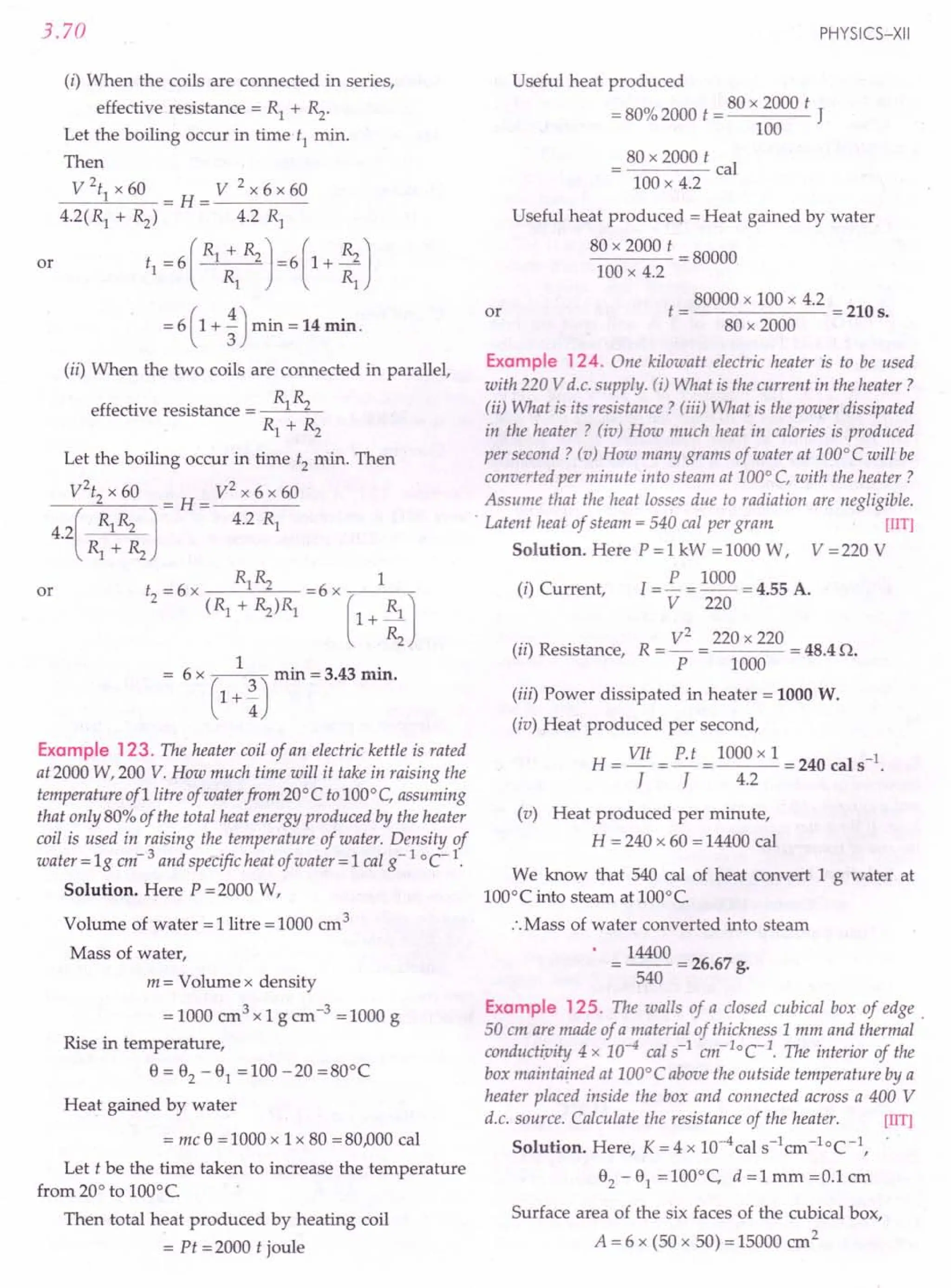
![CURRENT ELECTRICITY
The amount of heat conducted out per second
through the walls of the cubical box is
H _ KA(92-91)_ 4x 10-4 x 15000 x 100
I - d - 0.1
= 6000 cal = 6000 x 4.2 J
If R is the resistance of the heater, then heat produced
per second
. H2 = I2Rt = V
2
= (400)2 [t =ls]
R R
Temperature inside the box will be maintained by
the heater if
HI = H2 or (40~)2 = 6000 x 4.2
R = 400 x 400 = 6.35 Q
6000 x 4.2
Example 126. A 10 V battery of negligible internal
resistance is charged by a200 V d.c. supply. If the resistance
in the charging circuit is 38 Q, what is the value of charging
current ? [NCERT]
Solution. As the battery emf opposes the charging
emf, therefore,
or
net emf = 200 -10 = 190 V
Charging current,
I = Net emf = 200 -10 = 5 A.
Resistance 38
Example 127. A dry cell of emf 1.6 V and internal
resistance 0.10 ohm is connected to a resistor of resistance R
ohm. If the current drawn from the cell is 2 A, then
(i) what is the voltage drop across R ?
(ii) what is the energy dissipation in the resistor?
Solution. Here e =1.6 V, r=0.10Q, I =2.0 A
R + r = §. = 1.6 = 0.8 Q
I 2.0
R =0.8 -0.10 =0.70Q
(i) Voltage drop across R,
V = IR =2 x 0.70 = 1.4 V.
(ii) Rate of energy dissipation inside the resistor
= VI =1.4 x 2.0 = 2.8 W.
Example 128. A dry cell of emf 1.5 V and internal
resistance 0.10 Q is connected across a resistor in series with
a very low resistance ammeter. When the circuit is switched
on, the ammeter reading settles to a steady value of2.0 A
What is the steady
(a) rate of chemical.energy consumption of the cell,
(b) rate of energy dissipation inside the cell,
(c) rate of energy dissipation inside the resistor,
(d) power output of the source? [NCERT]
3.71
Solution. Here e = 1.5 V, r = 0.10 Q, 1=2.0 A
(a) Rate of chemical energy consumption of the cell
= eI = 1.5 V x 2.0 A = 3.0 W.
(b) Rate of energy dissipation inside the cell
=12
r =(2)2 x 0.10 W = 0.40 W.
(c) Rate of energy dissipation inside the resistor
= e I - I2r =3.0 -0.40 = 2.6 W.
(d) Power output of the source
= Power input to the external circuit
=eI - I2
r=2.6 W.
Example 129. A series battery of 10 lead accumulators,
each of emf 2 V and internal resistance 0.25 ohm, is charged
by a 220 V d.c. mains. To limit the charging current, a
resistance of 47.5 ohm is used in series in the charging
circuit. What is (a) the power supplied by the mains and
(b) power dissipated as heat? Account for the difference of
power in (a) and (b). [CBSE Sample Paper 98]
Solution. emf of the battery = 10 x 2 = 20 V
Internal resistance of the battery
=10 x 0.25 =2.5 Q
Total resistance = r + R = 2.5 + 47.5 = 50.0 Q
As the battery emf opposes the charging emf,
:. Effective emf =e - V =220 -20 =200 V
Ch
. Effective emf 200 4 A
argmg current = = - =
Total resistance 50
(a) Power supplied by the mains
= VI = 220 x 4 = 880 W.
(b) Power dissipated as heat
= p(R + r) = 42 x 50 = 800 W.
The difference of power =880 -800 =80 W, is
stored in the battery in the form of chemical energy.
Example 130. A series battery of6lead accumulators each
of emf2.0 V and internal resistance 0.50 Q is charged by a
100 V d.c. supply. What series resistance should be used in
the charging circuit in order to limit the current to 8.0 A ?
Using the required resistor, obtain (a) the power supplied by
the d.c. source (b) the power supplied by the d.c. energy
stored in the battery in 15 min. [NCERT]
Solution. Here e = 2.0 V, r = 0.50 Q, V = 100 V,
I =8.0 A
As the battery emf opposes the charging emf,
:. Effective emf =100 -2.0 x 6 =88 V
Let the required series resistance be of R Q.
Then
total resistance = (0.50 x 6 + R) Q = (3 + R) Q](https://image.slidesharecdn.com/slaroraclass12thphysicsbyrockytrickster-250318042948-c8b51a5a/75/SL-ARORA-CLASS-12TH-PHYSICS-BY-ROCKY-TRICKSTER-pdf-256-2048.jpg)
![3.72
Now
1 = Total emf
Total resistance
8=~
3+ R
or
64
R=-O =80.
8
(a) Power supplied by d.c. source
= VI = 100 V x 8 A = 800 W.
24 + 8R =88 or
(b) Power dissipated as heat
= P(R + r) =82
(8 + 0.50 x 6) W
= 64 x 11 W = 704 W.
(c) Power supplied by the d.c. energy stored in the
battery in 15 min
= (800 -704)W x 15 min
= 96 W x 900 s = 86400 J.
Example 131. Power from a 64 V d.c. supply goes to
charge a battery of 8 lead accumulators each of emf 2.0 V
and internal resistance 1/8 o. The charging current also
runs an electric motor placed in series with the battery. If the
resistance of the windings of the motor is 7.00 and the
steady supply current is 3.5 A, obtain
(a) the mechanical energy yielded by the motor,
(b) the chemical energy, stored in the battery during
charging in 1 h. [ CERT]
Solution. emf of the battery,
Eb = 2.0 x 8 V = 16 V
d.c. supply voltage, Es =64 V
Internal resistance of the battery,
1
r=-x80=10
8
Resistance of motor, R = 7.00
Let back emf of motor = Em
Both the back emf Em of the motor and the emf Eb of
the battery act in the opposite direction of the supply emf
E Therefore, net current in the circuit must be
s.
I = Net emf = Es -Eb -Em
Net resistance r + R
64 -16-E
or 3.5 = m
8
or Em = 48 -28 =20 V.
(a) Mechanical energy yielded by motor in 1 h
= Em. It =20 x 3.5 x 3600 J= 252000 J.
(b) Chemical energy stored in the battery in 1 h
= Eb. It = 16 x 3.5 x 3600 J = 201600 J.
PHYSICS-XII
Example 132. A 24 V battery of internal resistance 4.00
is connected to a variable resistor. At what value of the
current draum from the battery is the rate of heat produced
in the resistor maximum ? [ CERT]
Solution. Here E =24 V, r = 4.0 0
Let the variable resistor be R. The rate of heat
produced in the resistor will be maximum when
External resistance = internal resistance
or R=40
Required current,
emf 24
I= =--A=3.0A.
resistance 4 + 4
Example 133. 4 cells of identical emf E, internal
resistance r, are connected in series to a variable resistor. The
following graph shows the variation of terminal voltage of
the combination with the current output.
(i) What is the emf of
each cell used?
(ii) For what current from
the cells, does maxi-
mum power
dissipation occur in
the circuit?
(iii) Calculate the internal
resistance of each cell.
[CBSE 00 06C]
Solution. When I = 0,
5.6
t
~ 4.2
2
(3
..::. 2.8
:::.
1.4
o '----'----'_-'--->L_
0.5 1.0 1.5 2.0
I (ampere) -t
Fig. 3.132
total emf = terminal voltage
4E = 5.6 V
or E = 1.4
When I =1.0 A, V = 2.8 =0.7 V
4
Internal re istance
The output power is maximum, when
externaJ resistance = internal resistance = 4 r
Total emf 4 E
Total resistance 4r + 4r
=~=~=lA.
2r 2xO.7
Example 134. Two batteries, each of emf E and internal
resistance r, are connected in parallel. If we take current
from this combination in an external resistance R, then for
what value of R maximum power will be obtained? What
will be this power ?](https://image.slidesharecdn.com/slaroraclass12thphysicsbyrockytrickster-250318042948-c8b51a5a/75/SL-ARORA-CLASS-12TH-PHYSICS-BY-ROCKY-TRICKSTER-pdf-257-2048.jpg)
![CURRENT ELECTRICITY
Solution. The situation is shown in Fig. 3.133.
e
R
Fig. 3.133
Net emf of the parallel combination of two cells = E,
Total resistance in the circuit
=rxr+R=!.+R
r+ r 2
Hence current in the circuit is
I=_E,_=~
!.+R r+2R
2
Power dissipated in the resistance R is
P = PR = (2 E,)2 R = 4 E,
2
R
(r+2R)2 (r-2R)2+8rR
Power P will be maximum when the denominator or
has a minimum value. This happens when
(r - 2 R)2 = 0 or R = !.
2
E,2
P = (2E,l r/2
max (r+rl 2r
Example 135. Two wires made of tinned copper having
identical cross-section ( = 1O-
6
m2
) and lengths 10 em and
15 em are to be used asfuses. Show that thefuses will melt at
the same value of current in each case. [NCERT]
Solution. The temperature of the wire increases up
to a certain temperature ewhere the heat produced per
second by the current equals heat lost (by radiation)
per second.
But heat produced by the current
= I 2 R = l 2 P .!..- = I 2p/
A 1t?
If h is heat lost per second per unit surface area of
the wire and if we ignore the heat loss from the end
faces of the wire, then heat loss per second by the wire
= h x curved surface area of the wire
= h x 21trl
When the steady state temperature is attained,
[2 pI
hx21tr/=-.-2
1tr
or
Pp
h=-23 ...
(i)
21t r
3.73
Now h is independent of Iand the values of r and p
are same for both wires, hence steady state tempe-
rature e will depend only on I i.e., the two fuses will
melt at the same values of current.
Example 136. A fuse with a circular cross-sectional radius
of 0.15 mm blows at 15 A What should be the radius of
cross-section of afuse made of the same material which will
blow at 30 A ? [NCERT]
Solution. Here r1
=0.15 mm, II = 15 A, r2
=?
12 =30 A
From Eq. (i), the heat lost per second per unit
surface area of the wire is
Pp
h=--
21t2
r3
For a fuse wire of the given material and the
given value of h,
r3
oc I2
3 2
1'2 _ 12
3--2
r1 II
" I 2 3 (30)2
r2
" = ~ x r1
= - x (0.15)3
II - 15
r2
= (4)1/3 x 0.15 mm
= 1.5874 x 0.15 mm = 0.24 mm.
'Problems For Practice
or
1. Calculate the current flowing through a heater
rated at 2 kW when connected to a 300 V d.c.
supply. [CBSEF 94 Cl
(Ans. 6.67 A)
2. Calculate the amount of heat produced per second
(in calories), when a bulb of 100 W - 220 V glows
assuming that only 20% of electric energy is
converted into light. J = 4.2 J cal-1
. [Haryana 011
(Ans. 19.05 call
3. An electric heating element to dissipate 480 watts
on 240 V mains is to be made from nichrome ribbon
1mm wide and thickness 0.05 mm. Calculate the
length of the ribbon required if the resistivity of
nichrome is 1.1x 10- 6 Om. (Ans. 5.45 m)
4. 100 W, 220 V bulb is connected to 110 V source.
Calculate the power consumed by the bulb.
[Roorkee 861
(Ans. 25 W)
5. How many electrons flow per second through an
electric bulb rated 220 V, 100 W ? [BITRanchi 98]
(Ans. 2.84 x 10¹⁸
)
6. An ammeter reads a current of 30 A when it i.s
connected across the terminals of a cell of emf 1.5 V.](https://image.slidesharecdn.com/slaroraclass12thphysicsbyrockytrickster-250318042948-c8b51a5a/75/SL-ARORA-CLASS-12TH-PHYSICS-BY-ROCKY-TRICKSTER-pdf-258-2048.jpg)
![3.74
Neglecting the meter resistance, find the amount of
heat produced in the battery in 10 seconds?
(Ans. 107.14cal)
7. A coil of resistance 1000 is connected across a
battery of emf 6.0 V. Assume that .the heat deve-
loped in the coil is used to raise its temperature. If
the thermal capacity of coil is 4.0 JK-1
, how long
would it take to raise the temperature of the coil by
15°C? (Ans. 2.8 min)
8. A generator is supplying power to a factory by
cables of resistance 20O. If the generator is
generating 50 kW power at 5000V, what is the
power received by the factory? [Punjab 96 C]
(Ans. 48 kW)
9. Two bulbs are marked 220 V, 100 W and 220 V,
50 W respectively. They are connected in series to
220 V mains. Find the ratio of heats generated in
them. (Ans. 1 : 2)
10. In a house having 220 V line, the following applia-
nces are working: (i) a 60W bulb (ii) a 1000W heater
(iii) a 40W radio. Calculate (a) the current drawn by
heater and (b) the current passing through the fuse
line. [MNREC 86]
(Ans. (a) ~~ A (b) 5 A)
11. Three equal resistances connected in series across a
source of emf consume 20 W.If the same resistances
are connectedin parallelacrossthe same sourceof emf,
what will be the power dissipated? [Punjab 99]
(Ans. 180 W)
12. An 'electricheater consistsof 20m length of manganin
wire of 0.23 m2 cross-sectional area. Calculate the
wattage of the heater when a potential difference of
200 V is applied across it. Resistivity of manganin
= 4.6 x 10⁻⁷
Om. (Ans. 109
W)
13. A line having a total resistance of 0.20 delivers
10 kW at 220 V to a small factory. Calculate the
efficiency of the transmission. (Ans. 96%)
14. A motor operating on 120V draws a current of 2 A.
If the heat is developed in the motor at the rate of
9cal s-1, what is its efficiency? (Ans. 84.425%)
15. A 500 W electric heater is designed to work with a
200 V line. If the voltage of the line drops to 160V,
then what will be the percentage loss of the heat
developed? (Ans. 36%)
16. A 50W bulb is connected in a 200V line. Determine
the current flowing in it and its resistance. If 10%of
the total power is converted into light, then what will
be the rate of production of heat?
Take J = 4.2 J cal-1
(Ans. 0.25 A, 8000, 10.7 cal s-l)
PHYSICS-XII
17. Two bulbs rated 25 W, 220 V and 100W, 220 V are
connected in series to a 440 V supply. (i) Show with
necessary calculations which bulb if any will fuse.
(ii) What will happen if the two bulbs are connected
in parallel to the same supply?
[Ans. (i) 25 W bulb will fuse
(ii) Both the bulbs will fuse]
18. A servo voltage stabiliser restricts the voltage
output to 220V ± 1%. If an electric bulb rated at
220V, 100W is connected to it, what will be the
minimum and maximum power consumed by it ?
(Ans. 98.01W, 102.01W)
19. A room is lighted by 200 W, 124 V incandescent
lamps fed by a generator whose output voltage is
130 V. The connecting wires from the generator to
the user are made of aluminium wire of total length
150 m and cross-sectional area 15 mm2. How many
such lamps can be installed ? What is the total
power consumed by the user? Specific resistance of
aluminium = 2.9 x 10⁻⁸ Om. (Ans. 12, 2.4 kW)
20. Two wires A and Bof same material and mass, have
their lengths in the ratio 1 : 2. On connecting them,
one at a time to the same source of emf, the rate of
heat dissipation in Bis found to be 5 W. What is the
rate of heat dissipation in A ? (Ans. 20 W)
21. Two electric bulbs rated as 100W, 220 V and 25 W,
220 V are connected in series across 220 V line.
Calculate (i) current through (ii) potential difference
across and (iii) actual powers consumed in filament
of each bulb.
(Ans. (i) 1 A (ii) 44 V, 176V, (iii) 4 W, 16W)
22. The heater coil of an electric kettle is rated as 2000W
at 200 V. How much time will it take to heat one
litre of water from 20°C to 100°C, assuming that
entire electric energy liberated from the heater coil
is utilised for heating water ? Also calculate the
resistance of the coil. Density of water is 1g ern-3.
(Ans. 168 s, 200)
23. An electric kettle was marked 500W, 230V and was
found to raise 1 kg of water at 15°C to the boiling
point in 15 minutes. Calculate the heat efficiency of
the kettle. (Ans. 79.3%)
24. A copper kettle weighing 1000 g holds 1900 g of
water at 19°C It takes 12 minutes to raise the
temperature to 100°C.If energy is supplied at 210V,
calculate the strength of current, assuming that 10%
of heat is wasted. Specific heat of copper
= O.lcal s' eel. (Ans. 5.0 A)
25. A 30 V storage battery is being charged by 120V d.c.
supply. A resistor has been connected in series with
the battery to limit the charging current to 15 A.](https://image.slidesharecdn.com/slaroraclass12thphysicsbyrockytrickster-250318042948-c8b51a5a/75/SL-ARORA-CLASS-12TH-PHYSICS-BY-ROCKY-TRICKSTER-pdf-259-2048.jpg)
![CURRENT ELECTRICITY
Find the rate at which energy is dissipated in the
resistor. If the total heat produced could be made
available for heating water, how long would it take
to bring 1 kg of water from 15°C to the boiling
point? Specific heat of water =lcalg-I
oC-1
and
1cal = 4.2J. [MNREC 84]
(Ans. 1350Js-1, 264.4s)
26. In the circuit shown in Fig. 3.134, each of the three
resistors of 4n can have a maximum power of 20W
(otherwise it will melt). What maximum power can
the whole circuit take? (Ans. 30 W)
H2
4Q
4Q
Fig. 3.134
27. Find the heat produced per minute in each ofthe resis-
tors shown in Fig. 3.135. (Ans. 360 J, 720J, 540 J)
II 6Q
9V i n
Fig. 3.135
28. Calculate the current drawn from the battery of emf
15 V and internal resistance 0.5n in the circuit
shown in Fig. 3.136.Also find the power dissipated
in the 6n resistor. [lIT]
(Ans. 1.0 A, 3.375W)
2 Q I -II 7 Q
15 V, -=-
0.5 Q-=-
lQ
8Q
Fig. 3.136
29. In the circuit shown in Fig.3.137,the heat produced
by 4 n resistance due to current flowing through it
is 40cal s-1. Find the rate at which heat is produced
in 2n resistance. (Ans. 80cal s-1)
2Q 3Q
Fig. 3.137
4Q 6Q
3.75
30. The 2.0n resistor shown in Fig. 3.138is dipped into
a calorimeter containing water. The heat capacity of
the calorimeter together with water is 2000JK-1
.
(a) If the circuit is active for 30 minutes, what would
be the rise in the temperature of the water ?
(b) Suppose the 6.0n resistor gets burnt. What
would be the rise in the temperature of the water in
the next 30 minutes? (Ans. 5.8°C, 7.2°q
6V lQ
2Q
Fig. 3.138
31. Three resistors ~,Rz and Rs each of 240o are
connected across a 120V supply, as shown in
Fig. 3.139. Find (i) the potential difference across
each resistor and (ii) the total heat developed across
the three resistors in 1 minute.
[Ans. (i) VI = 80 V, (ii) V2 = V3 = 40 V (iii) 2400JJ
RI
120V
Fig. 3.139
32 A heating coil is connected in series with a
resistance R The coil is dipped in a liquid of mass
2 kg and specific heat 0.5calg-1
°C-I
. A potential
difference of 200 V is applied and the temperature
of the liquid is found to increase by 60°C in 20
minutes. If R is removed, the same rise in,
temperature is reached in 15 minutes. Find the
value of R (Ans.22.14n)
33. A house is fitted with two electric lamps, each of
100W ; one heater of resistance 110n and two fans,
each consuming 0.25A.If electric energy is supplied
at 200V and each appliance works for 5 hours a day,
find the monthly bill at the rate of Rs.3.0per kWh.
[Punjab 98C] (Ans. ~298.65)
34. An electric kettle has two coils. When one coil is
switched on, it takes 5 minutes to boil water and
when second coil is switched on, it takes 10
minutes. How long will it take to boil water, when
both the coils are used in series? [Punjab 01]
(Ans. 15 minutes)](https://image.slidesharecdn.com/slaroraclass12thphysicsbyrockytrickster-250318042948-c8b51a5a/75/SL-ARORA-CLASS-12TH-PHYSICS-BY-ROCKY-TRICKSTER-pdf-260-2048.jpg)
![3.76
35. A series battery of 6 lead accumulators, each of emf
2.0 V and internal resistance 0.25 n is charged by a
230 V d.c. mains. To limit the charging current, a
series resistance of 53 n is used in the charging
circuit. What is (i) power supplied by the mains
(ii) power dissipated as heat ? Account for the
difference in the two cases. [NCERT]
(Ans. 920 W, 872 W)
36. A storage battery of emf 8 V, internal resistance 1n, is
being charged by a 120 V d.c. source, using a 15n
resistor in series in the circuit. Calculate (i) the
current in the circuit, (ii) terminal voltage across the
battery during charging, and (iii) chemical energy
stored in the battery in 5 minutes. [CBSE 01, 08]
[Ans. (i) 7 A, (ii) 15 V, (iii) 16800 JJ
37. The following graph shows the variation of terminal
potential difference V, across a combination of three
cells in series to a resistor,
versus the current, i: 6.0
(i) Calculate the emf of
each cell t
:::.3.0
(ii) For what current i, will
the power dissipation
of the circuit be maxi- . 0
mum? [CBSE OD 08]
l.0 2.0 i---t
(Ans. 2.0 V, 1.0 A) Fig. 3.140
PHYSICS-XII
5, n ~ !!.. = £!.. = 100 x 1 = 2.84 x10¹⁸
e Ve 220x1.6x10-19
6. If r is the internal resistance of the cell, then
1= ~ or r = §. = 1.5 = 0.05 n
r 1 30
H
12 rt (30)2 x 0.05 x 10
= -- = = 107.14 cal.
J 4.2
7. Heat required by the coil = Thermal capacity
x rise in temperature
= 4.0 x 15 = 60 J
Rate of production of heat,
V2
6 x6
p=-=-- = 0.36 Js-1
R 100
R . d . 60J 60 .
.. eqUire time = 0.36 Js-l 0.36 x 60 rrun
'" 2.8 min.
8. Here P = SO:kW :0 50 x 103W, V = 5000 V
Current supplied by generator,
P 50 x 103
l=-= =lOA
V 5000
Power wasted as heat during transmission by
cables of 20.n resistance,
P' = [2R = (10)2 x 20 = 2000 W = 2 kW
Power received by the factory
= P'- P=50-2=48 kW.
220 x 220 220 x 220
9. 1), = 100 = 484n, ~ = 50 = 968n
Ratio of heats produced whenconnected in series,
Ii = [21), = ~ = 484 = 1: 2
~ [2~ ~ 968
R 1000 50
10. (a) Current drawn by heater = -1. = -- = - A
V 220 11
Current drawn by bulb = ~ = ~ = ~ A
V 220 11
Cu d b -_!i~_
,_40 -_--12 A
rrent rawn y radio -
V 220 11
(b) Current passing through fuse for the line
50 3 2
=-+-+-=5A.
11 11 11
11. Let R be the resistance of each resistor and ethe emf
of the source.
For series combillatioll: Rs = R + R + R = 3 R
V2
V2
V2
P=- or 20=- •. -=60W.
Rs 3 R R
For parallel combination: Rp = R/3
V2
V2
3 V2
p'=-=-- =--=3 x60=180W.
Rp R/3 R
HINTS
P 2kW 2000W
1. [= - = -- = = 6.67 A.
V 300V 300 V
2. Power of bulb, P = 100 W
•.Electric energy consumed per second = 100 J
Amount of heat produced per second
80
= 80"/0of 100 J = 80 J = - cal = 19.05 cal.
4.2
V2 V2 240 x 240
3. Power, P = - .. R = - = = 120n
R p 480
I Area of cross-section of the ribbon,
A = 0.05 mm 2 = 0.05 x JQ-om 2
Required length,
RA 120 x 0.05 x 10-6
1= - = 6 m = 5.45 m.
p 11 x 10-
Here P = 100 W, V = 220 V
V2
220 x 220
:. Resistance of bulb, R = - = = 484 n
P 100
When the bulb is connected to 110 V source, the
power consumed by the bulb is
V,2 110 x 110
P'=-= =25W.
R 484](https://image.slidesharecdn.com/slaroraclass12thphysicsbyrockytrickster-250318042948-c8b51a5a/75/SL-ARORA-CLASS-12TH-PHYSICS-BY-ROCKY-TRICKSTER-pdf-261-2048.jpg)
![CURRENT ELECTRICITY
12. First find R = P ~ and then P = ~ .
A R
13. Let P' be the power loss in the transmission line in
the form of heat. Then
P' = [2R = (~rR = c~~~or
x 0.2
= 413.2W = 0.4132 kW
Efficiency of transmission,
Power delivered by line
11 = Power supplied to line
Power delivered
Power delivered + Power loss
10
---- = 0.96 = 96%.
]0 + 0.4132 .
14. Power supplied to line = VI = 120 x 2 = 240 W
Power loss in the form of heat
=9cals-1
=9x4.2}s-1 = 37.8 W
Power delivered by line = 240 - 37.8 = 202.2 W
Effi . Power delivered by line 202.2
ICIency, 11 = -------"---
Power supplied to line 240
= 0.8425 = 84.25%.
15. Here P = 500 W, V = 200 V
R = V
2
= 200 x 200 = 80n
P 500
When the voltage drops to 160 V, rate of heat
production is
P' = V
,2
= 160 x 160 = 320 W
R 80
% Drop in heat production
P- pi 180 x 100
=-- x100= =36%.
P 500
17. Proceed as in Example 117 on page 3.68.
(220)2
18. Resistance of the bulb, R = -- = 484 n
100
Variation in voltage = ± 1% of 220 V = ± 2.2 V
Minimum voltage = 220 - 2.2 = 217.8 V
Mi . -_(217.8)2 -_98.01 W.
mmum power
484
Maximum voltage = 220 + 2.2 = 222.2 V
Maximum power = (222.2)2 = 102.01 W.
484
19. Resistance of aluminium wire,
R _ pi _ 2.9 x 10- 8 x 150
- A-IS x 10- 6 = 0.29n
.. 130 -124
Current from the mam Ime = = 20.69 A
0.29
3.77
200
Current through each lamp = - = 1.613 A
124
:.No. of bulbs which can be used = 20.69 = 12.83.
1.613
No. of bulbs that should be installed = 12.
Power consumed = 12 x 200 = 2400 W = 2.4 kW.
20. As the two wires are of same material and mass,
their volumes must be equal.
:. ~~ = a212 or ~ x 1= a2 x 21 or ~ = 2a2
If E, is the emf of the source, then rate of heat
dissipation in wire B is
E,2
-=5 or
~
E,2
---=5 or
p.21/a2
or
E,2
--=5
P 12/ a2
E,2 a
__ 2 =10
pi
Rate of heat dissipation in wire A is
E,2 €,2 E,2
- = -- =-.2a2
=2 x10=20W.
~ p 1/ ~ pI
21. Proceed as in Example 123 on page 3.70.
22. [= i = 2000 = 10 A
V 200
.. VIt 200 x 10 xt
Heat produced m time t = - = cal
J 4.2
Heat gained by water = mdJ = 1000 x 1 x 80 cal
2000t
.. -- = 1000 x80
4.2
1000 x 80 x 4.2
or t = = 168 s.
2000
R= V
2
= 200 x 200 =20n.
P 2000
23. Heat absorbed by water
= 1 x 4200 x(100 - 15) = 4200 x 85 J
Heat produced by electric kettle
= Pt = 500 x 15 x 60 J
. . 4200 x 85
Heat efficiency = x 100 = 79.3%.
500 x 15 x 60
24. Proceed as in Example 120 on page 3.69.
. 120 - 30
25. Chargmg current, l = = 15
R
S
· . R 90
:. enes resistor, = - = 6 n
15
Rate of energy dissipation in the resistor,
P= [2R =(15)2 x 6 =1350 }S-l.
Heat produced in resistor in time t = Heat absorbed
by water
1350 x t = 1 x 4200 x(100 - 15)
4200 x85
t = = 264.4 s.
1350
or](https://image.slidesharecdn.com/slaroraclass12thphysicsbyrockytrickster-250318042948-c8b51a5a/75/SL-ARORA-CLASS-12TH-PHYSICS-BY-ROCKY-TRICKSTER-pdf-262-2048.jpg)
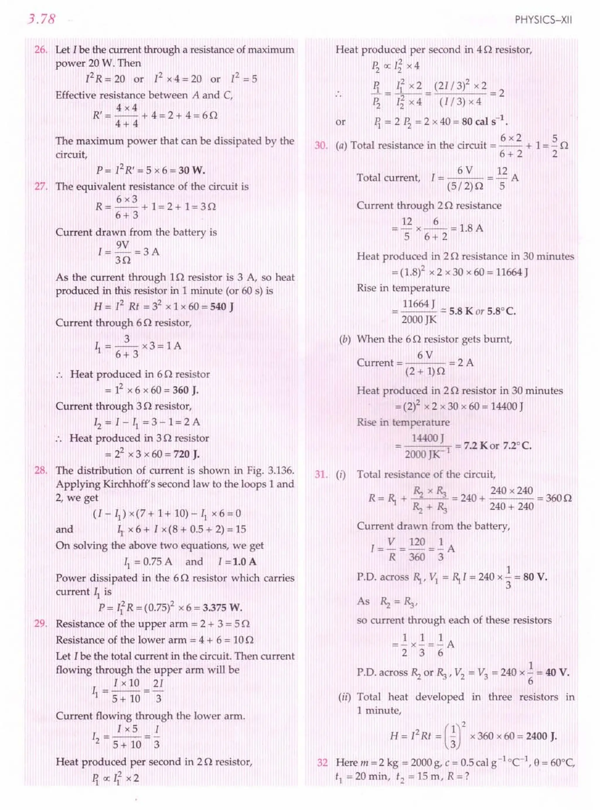
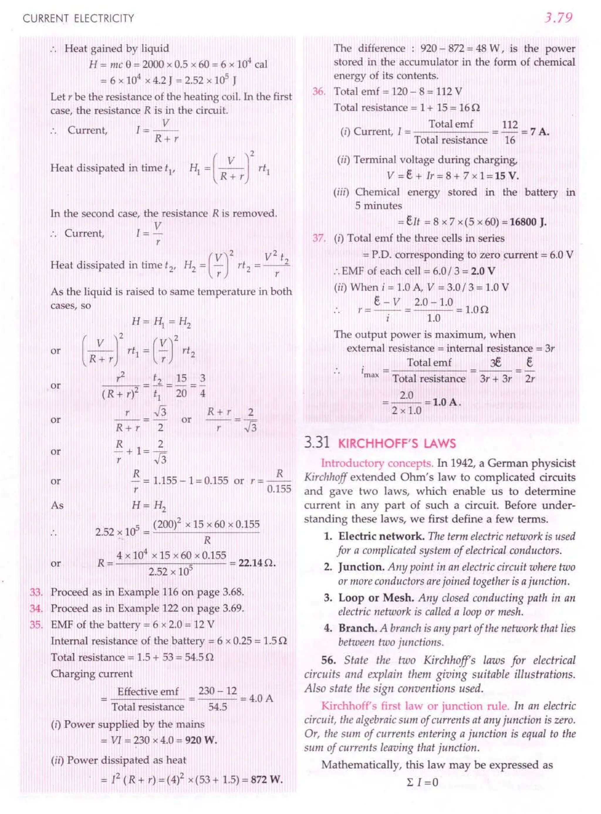
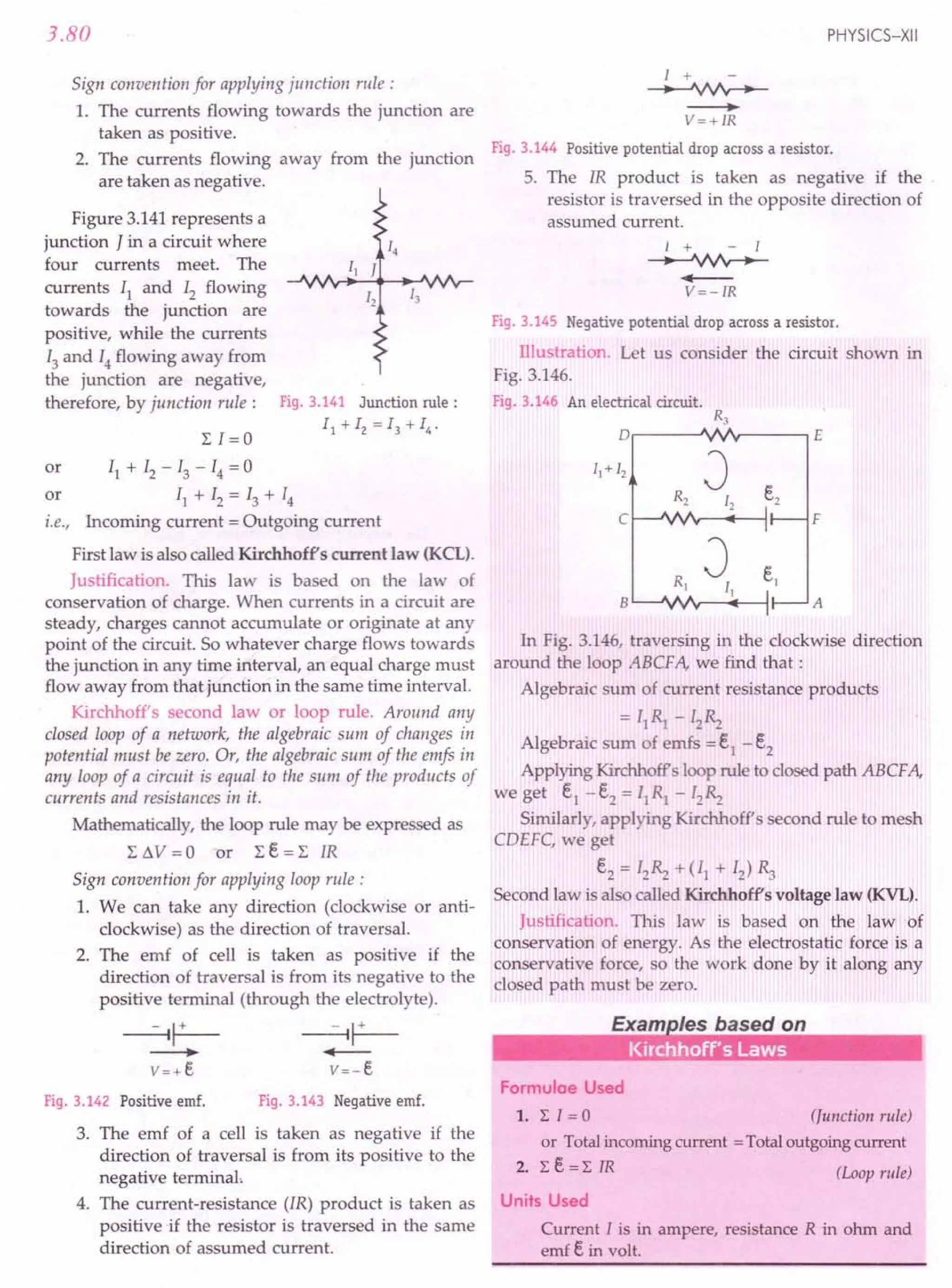
![CURRENT ELECTRICITY
Example 137. Network PQRS (Fig. 3.147) is made as
under: PQ has a battery of 4 V and negligible resistance
with positive terminal connected to P, QR has a resistance of
60 n. PS has a battery of 5 V and negligible resistance with
positive terminal connected to P, RS has a resistance of
200 n. If a milliammeter, of 20 n resistance is connected
between P and R, calculate the reading of the milliammeter.
[NCERT]
200n
R
5V
60n
J
p Q
4V
Fig. 3.147
Solution. Applying Kirchhoff's second law to the
loop PRQP, we get
20[1 + 60[ = 4
Similarly, from the loop PSRP, we get
200 (l- II) -20[1 = - 5
40[ -4411
=-1
Multiplying (i) by 2 and (ii) by 3, we get
120[ + 4011
= 8
and 1201-132 II = -3
Subtracting (iv) from (iii), we get
172[1 =11
[ =~ =0.064 A
1 172
or
...(iii)
...(iv)
or
Thus the milliammeter of 20 o will read 0.064 A.
Example 138. UsingKirchhoff's laws in theelectricalnetwork
shown in Fig. 3.148, calculate the values of II' 12and 13,
[CBSE D 2000q
ABC
F E o
Fig. 3.148
Solution. Applying Kirchhoff's first law at junction B,
II + [2 =13 ...(1)
Applying Kirchhoff's second law to loops ABEFA
and BCDEB, we get
213 + 511 = 12 (2)
- 213 - 3[2 = - 6 (3)
3.81
Solving equations (1), (2) and (3), we get
48 18 66
II = - A, 12= - A, [3 = - A
31 31 31
Example 139. Find the potential difference across each cell.
and the rate of energy dissipation in R. [Fig. 3.149(ti)}.
[CBSE Sample Paper 11]
e1 = 12 V '1 = 2 o
R=4n
...(i)
Fig.3.149(a)
Solution. Applying Kirchhoff's laws,
For closed loop ADCBA
12 = 4(Il + 12)+2 II =6 II + 4 12
For closed loop ADEFA,
6 = 4(Il + 12) + II = 4 11 + 5 12 ...(il)
...(i)
...(ii)
R=4n
A•.......•..
-----'Nr--___. 0
F '-- ...•..
---l:1---..JVV'v----' E
12
Fig. 3.149(b)
Solving (i) and (ii), we get
[ = 18A and I = -~A
1 7 2 7
P'D, across R = V
= (II + I2)R
(
18-6) 48
= -7- x 4 volt ='7 volt
P'D. across each cell = p.o. across R = 48 V
7
Energy dissipated in R = 4 n resistor
2 (12)2
= (II + [2) R = '7 x 4}
= 576 J = 11.75 J.
49](https://image.slidesharecdn.com/slaroraclass12thphysicsbyrockytrickster-250318042948-c8b51a5a/75/SL-ARORA-CLASS-12TH-PHYSICS-BY-ROCKY-TRICKSTER-pdf-266-2048.jpg)
![to write the
in the circuit
[CBSEOD 10]
Fig.3.153 (a)
3.82
Example 140. Two cells of emfs 1.5 V and 2.0 V and
internal resistances 1n and 2 n respectively are connected
in parallel so as to send current in the same direction
through an external resistance of 5 n. [CBSE OD 05]
(i) Draw the circuit diagram.
(ii) Using Kirchhoff's laws, calculate
(a) current through each branch of the circuit.
(b) p.d. across the 5 n resistance.
Solution. (I) The circuit diagram is shown in Fig. 3.150.
J
B
r----------
: I 1Q
FQ- .....•
~---l
: I v v :
:__1~~
": ~~ .:
c
J
Fig. 3.150
(ii) (a) Let II and Iz be the currents as shown in
Fig. 3.150. Using Kirchhoff's second law for the loop
AFCBA, we get
2 Iz - 1Il = ~ - E.l = 2 -1.5
or 2Iz - II = 0.5 ...(1)
For loop CFEDC, we have
1Il + 5(11 + Iz) = e, = 1.5
or 5Iz + 611
= 1.5 ...(2)
Solving equations (1) and (2), we get
1 9
II = 34 A, Iz = 34 A
.'. Current through branch BA,
1
II =-A
34
Current through branch CF,
9
Iz=-A
34
Current through branch DE,
10
11
+ Iz =- A
34
(b) P.D. across the 5 o resistance
10
= (11 + Iz) x 5 = - x 5 V = 1.47 V.
34
Example 141. Use Kirchhoffs rules
expressions for the currents I1
,Iz and 13
diagram shown in Fig. 3.151.
PHYSICS-XII'
11
e1~2V
'1 ~4Q
12
e2~ 1 V
'2~3Q
)
13
e3~4 V r3~2Q )
Fig.3.151
Solution. By Kirchhoff's junction rule,
13 = II + Iz ...(i)
From upper loop,
3Iz-4I1
=2-1=1 ...(ii)
From lower loop,
3Iz+2I3=4-1=3 ...
(iii)
On solving equations (i), (ii) and (iii), we get
II =~A Iz =2.A I =~A
13 13 3 13
Example 142. Apply Kirchhoffs rules to the loops ACBPA
and ACBQA to write the expression for the currents II' Iz
and 13 in the network shown in Fig. 3.152. [CBSE OD 10]
Solution. By Kirchhoff's e1 ~ 6V
junction rule, P
13 = II + 12 ... (1)
From loop AQBP A,
0.5 II - 12 = 6 -10 = -4
...(ii)
c
From loop ACBP A,
12 13 +0.5 II = 6
...(iii) Fig.3.152
On solving equations (i), (ii) and (iii), we get
I = - 84 A I = 106 A I = _ 22 A
1 37 2 37 3 37
R~12Q
Example 143. Use Kirchhoffs rules to detemine the
potential difference between the points A and D when no
current flows in the arm BE of the electric network shown in
Fig. 3.153(a). [CBSE OD 15]
3Q E
F ,-.JVIr-.----,D
::AL~
B
6V 4V
R
c](https://image.slidesharecdn.com/slaroraclass12thphysicsbyrockytrickster-250318042948-c8b51a5a/75/SL-ARORA-CLASS-12TH-PHYSICS-BY-ROCKY-TRICKSTER-pdf-267-2048.jpg)
![CURRENT ELECTRICITY
Solution. No current flows through the arm BE.
Let I be the current along the outer loop as shown
in Fig. 3.153(b).
3Q E
F.-~~~ __-.~~D
I
~:eR1
T
3V
,
A I r---:----i
6V B 4 V
R
c
Fig. 3.153 (b)
Applying Kirchhoff' loop rule to the loop AFEBA,
(2 +3)1+ Rl xO =1+3+6
I =2A
From A to D along AFD,
VAD =2 x2 -1+3x2 =9 V.
Example 144. In the circuit Fig. 154, assuming point A to
be at zero potential, use Kirchhoffs rules to determine the
potential at point B.
0
4V
lA 3A
II B
R 2Q R1
2V
3A
II
A C
Fig. 3.154
Solution. From the loop BDCR1
B, we get
2 x 2 + 3 Rl = 4 or Rl = 0
3.83
Solution. Let I}, 12 and 13 be the currents as shown
in Fig. 3.155. Kirchhoff's second rule for the closed
loop ADCA gives
10- 4( II - 12) + 2{ 12 + 13 - II) - II = 0
or 711
-612
-213
=10 ...(1)
For the closed loop ABCA, we get
10 - 4 [2 - 2(12 + 13) - 11 = 0
or 11
+612
+213
=10 ...(2)
For the closed loop BCDEB, we get
5 - 2 (I2 + 13) - 2 (I2 + 13 - II) = 0
or 2 11 - 4 12 - 4 13 = - 5 ...(3)
On solving equations (1), (2) and (3), we get
5 7
I} =2.5 A, 12 =8" A, 13 =18 A
The currents in the various branches of the network
are:
5
IAB=-A;
8
7
lAD = 1- A;
8
1
ICA =2- A;
2
7
IDEB =1- A
8
1
I
BC
=2- A.
2
ICD = 0;
Example 146. In the circuit shown in Fig. 3.156(a), E, F,
e and H are cells of emf 2 V, 1 V, 3 V and 1 V, and their
internal resistances are 2 Q, 1Q, 3 Q and 1Q, respectively.
Calculate (i) the potential difference between Band D and
(ii) the potential difference across the terminals of each of the
cells e and H. [CBSE D 04C ; CBSE Sample Paper 08]
D""-----~
Example 145. Determine the current in each branch of the
network shown in Fig. 3.155. [NCERT] Fig.3.156(a)
B
D
Fig. 3.155
Solution. In Fig. 3.156(b), the network has been
redrawn showing the ernfs and internal resistances of
the cells explicitly.
2Q 2 V I
1 :~I---<II!-:-Il-H"""~2
1 VI F I, ~:slll:
",,---
•.. _G-I C
D
12 3 V 3 Q
Fig. 3.156(b)](https://image.slidesharecdn.com/slaroraclass12thphysicsbyrockytrickster-250318042948-c8b51a5a/75/SL-ARORA-CLASS-12TH-PHYSICS-BY-ROCKY-TRICKSTER-pdf-268-2048.jpg)
![3.84
(i) Applying Kirchhoff's first law at junction D,
we get
I = II + 12 ...(i)
Applying Kirchhoff's second law to loop ADBA, we
get
2 1+ I + 2 II = 2 -1
or 3I+2I1=1 ...(ii)
Applying Kirchhoff's second law to loop DCBD
3 12 + 12 - 2 II = 3 - 1
or 412 -2I1 =2 ...(iii)
On solving equations (i), (ii) and (iii), we get
1 6 5
II = - 13 A, 12= 13 A and I = 13 A
P.D. between the points Band D,
2
VI = II x 2 = - V.
13
(ii) PD. between the terminals of G (giving current),
6
V2 = e - I? r =3 - - x 3 = 1.615 V
- 13
PD. between the terminals of H (taking current),
V3 = e' + 12
r' = 1 + ~ x 1 = 1.46 V.
13
Example 147. In a Wheatstone bridge, p=ln,
Q =2 n, R =2 n, 5 =3 nand Rg = 4 n. Find the current
through the galvanometer in the unbalanced position of the
bridge, when a battery of2 V and internal resistance 2 n is
used.
Solution. The circuit for the given Wheatstone
bridge is shown in Fig. 3.157. Let I, II and Ig be the
currents as shown.
B
2V
E
2Q
Fig. 3.157
Applying Kirchhoff's second law to loop ABDA,
we get,
II x 1 + 1g x 4 - (I - II) x 2 = a
or 311
-2I+4Ig=0 ...(1)
PHYSICS-XII
Applying Kirchhoff's second law to loop BCDB,
we get
(II-1 )x2-(I-l1+1 )x3-1 x4=0
g . g g
5I1 -31 -9Ig =0 ...(2)
Applying Kirchhoff's second law to loop ADCEA,
we get
or
2(1 - II) + 3(I - II + Ig)+2I=2
- 5 II + 71 + 3 Ig = 2 ...(3)
Adding (2) and (3),
41-6Ig=2 ...(4)
Multiplying (1) by 5 and (2) by 3 and subtracting,
we get
-1 + 471g = a or
From (4),
4 x 47Ig -6Ig = 2 or 182 Ig = 2
2 1
I =-=-A.
g 182 91
Example 148. The four arms of a Whetstone bridge
(Fig. 3.158) have the following resistances:
AB=100n, BC=10n, CD=5n and DA=60n.
A galvanometer of 15 n resistance is connected across
BD.Calculate the current through the galvanometer when a
potential difference ofl0 V is maintained across AC.
[NCERT]
B
o
lOV
Fig. 3.158
Solution. Applying Kirchhoff's second law to loop
BADB, we get
100I1 + 15Ig -6012
= a
or 20I1
+3Ig-1212=0 ...(1)
Considering the loop BCDB, we get
10 (II - Ig) -15Ig - 5 (I2 + Ig) =0
1011 -30Ig -512
=0
2 II - 61g - 12 = a ...(2)](https://image.slidesharecdn.com/slaroraclass12thphysicsbyrockytrickster-250318042948-c8b51a5a/75/SL-ARORA-CLASS-12TH-PHYSICS-BY-ROCKY-TRICKSTER-pdf-269-2048.jpg)
![CURRENT ELECTRICITY
or
Considering the loop ADCEA, we get
6012 +5(12 + Ig
}=l0
6512 + 5Ig = 10
1312 + Ig =2
Multiplying Eq. (2}by 10, we get
2011 -60Ig -1012 =0
From equations (I) and (4), we get
631 -212 = 0
g 63
12 = 2 Ig =31.5Ig
Substituting the value of 12in Eq. (3), we get
13 (31.51g) + Ig = 2
410.5Ig=2
2
I = --- A =4.87 mA.
g 410.5
or
Example 149. Two cells of emfs 1.5 V and 2 V and
internal resistances 2 0 and 10 respectively have their
negative terminals joined by a wire of 60 and positive
terminals by a wire of 40 resistance. A third resistance wire
of 80 connects middle points of these wires. Draw the
circuit diagram. Using Kirchhoff laws, find the potential
difference at the end of this third wire. [CBSE D 2000c]
Solution. As shown in Fig. 3.159, the positive
terminals of cells e1 and e2 are connected to the wire
AE of resistance 4 0 and negative terminals to the wire
BD of resistance 6 O. The 80 wire is connected
between the middle points F and C of the wires AE and
BD respectively.
4
Rl=~=2=20
6
R=R=-=30
342
and
The distribution of current in various branches is
shown in Fig. 3.159.
RJ=30
II
O-.•....
---"vv'r--...•..
--{)C
[2
R4=30
Fig. 3.159
Applying Kirchhoff's second law to the loop
ABCF A, we get
3.85
...(3}
I] x '1 + II x R] + (11 + I2) R + I] x R3 = e1
II x 2 + II x 2 + (11 + 12
) x 8 + II x 3 = 1.5
1511 +812 =1.5
Applying Kirchhoff's second law to the
CDEFC, we get
12x r2 + 12x ~ + (II + 12) x R + 12x R4 = e2
12x 1 + 12x 2 + (11 + 12)x 8 + 12x 3 =2
811
+ 1412 =2
or 4 II + 712 = 1
On solving equations (i) and (ii), we get
5 18
1[ = 146 A and 12 = 146 A
Current through the 80 resistance wire is
I + I =2+~=E...A
1 2 146 146 146
PD. across the ends of 8 0 resistance wire
= E... x 8 = 1.26 V.
146
Example 150. AB, BC, CD and DA are resistorsof L, 1,2
and2 0 respectively connected in series. Between A and Cis
a 1 volt cell of resistance 2 0, A being positive. Between B
and D is a 2 V cell af1 0 resistance, B being positive. Find
the current ill each branch of the circuit.
Solution. The circuit arrangement and current
distribution is shown in Fig. 3.160.
B
... (i}
loop
...(4}
...(ii}
A C
20 I3 - II 20
[3 - I2 IV U
F E
20
Fig. 3.160
Applying Kirchhoff's second law to loops BADB,
BCDB and ADCEFA, we get
1. 12+ 2 . 13 + 1. II = 2
or 11+12+213=2 ...(1}
or 1(/1-12}-2(13-Il}+11=2
or 4 II - 12- 2 13= 2 ...(2}
and 213+2(13-11}+2(13-12}=1
or - 2 II - 2 12 + 6 13= 1 ...(3}
Solving equations (I), (2) and (3), we get
II =0.8 A, 12=0.2 A and 13 =0.5 A](https://image.slidesharecdn.com/slaroraclass12thphysicsbyrockytrickster-250318042948-c8b51a5a/75/SL-ARORA-CLASS-12TH-PHYSICS-BY-ROCKY-TRICKSTER-pdf-270-2048.jpg)
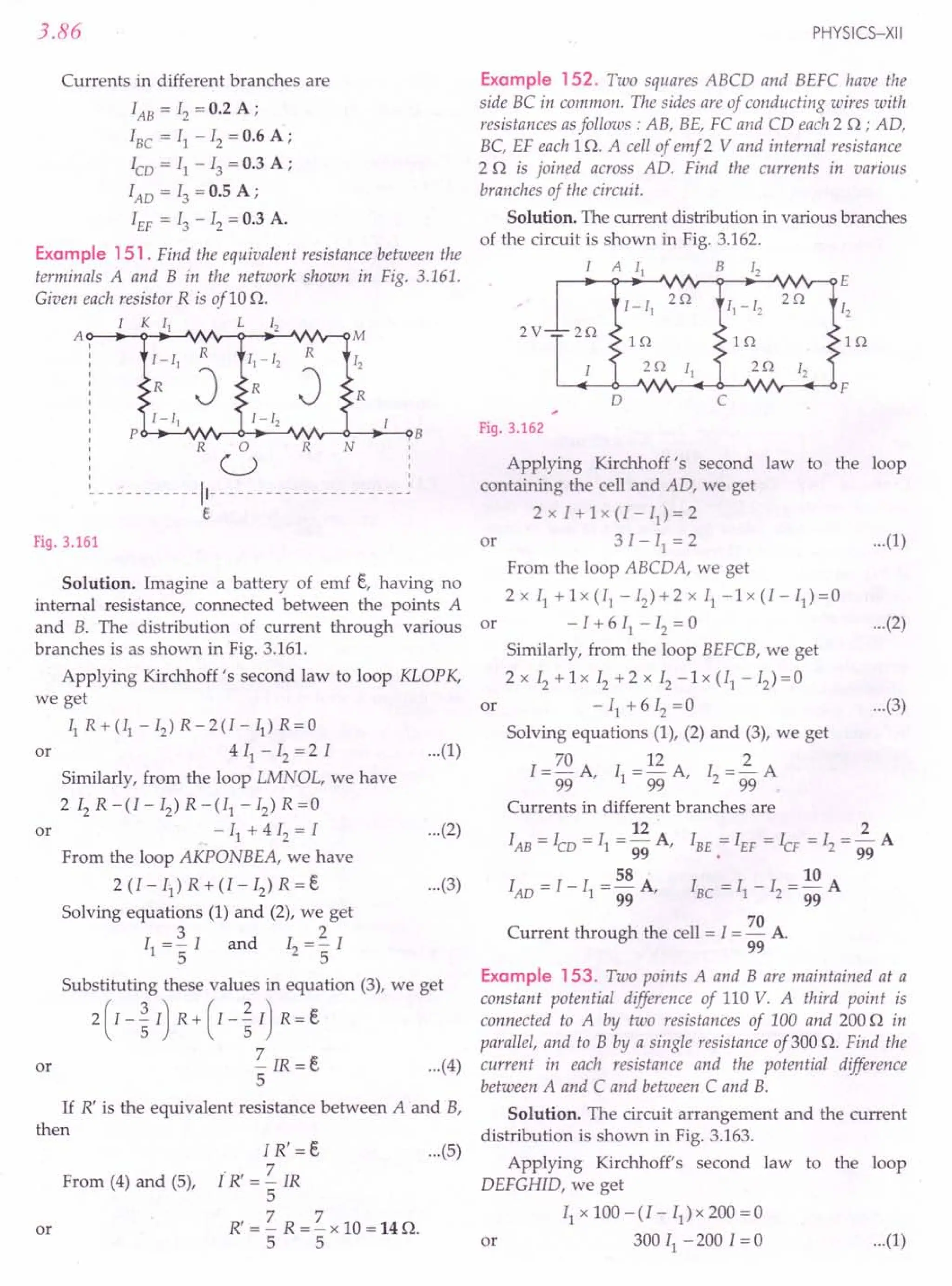
![CURRENT ELECTRICITY
c
I--+---~B
Fig. 3.163
Similarly, from loop ADIHGCBA, we get
(I - 11
)200 + Ix 300 = 110
or 500 1-200 II = 110 ...(2)
Solving equations (1) and (2), we get
3 1
I = 10 A and II = 5" A
.'. Current through 100 0 resistance
1
= II =- A
5
Current through 200 0 resistance
1
=I-Il=-A
10
Current through 300 0 resistance
=I=-2.A
10
P.D. between A and C = PD. across 100 n resistor
1
= II x 100 = - x 100 = 20 V
5
PD. between C and B = PD. across 300 0 resistor
= I x 300 = 2.x 300 = 90 V.
10
Example 154. A battery of 10 V and negligible internal
resistance is connected across the diagoYfallyopposite corners
of a cubicalnetwork consisting of12 resistorseachof resistance
10. Determine the equivalent resistance of the network and
the current along each edge of the cube. [NCERT]
Solution. Let 61 be the current through the cell.
Since the paths AA', AD and AB are symmetrically
placed, current through each of them is same, i.e., 21.At
the junctions A', Band D the incoming current 21splits
equally into the two outgoing branches, the current
through each branch is I, as shown in Fig 3.164. At the
junctions B', C and D', these currents reunite and the
currents along B'C', D' C' and CC' are 21each. The total
current at junction C' is 61 again.
Applying Kirchhoff's second law to the loop
ABCC' EA, we get
- 2 IR - 1R - 2 1R .+. e = a or e= 5 IR
where R is the resistance of each edge and e is the emf
of the battery.
3.87
61
E
Fig. 3.164
.. The equivalent resistance of the network is
R' = Total emf = ~ = 5 IR = ~ R
Total current 61 6 I 6
But R=10
R'=~O
6
Total current in the network is
e 10
6 I = - = - = 12 A or I = 2 A
R' 5
6
The current flowing in each branch can be read off
easily.
Example 155. Twelve wires eachhaving a resistance of r 0
are connected toform a skeleton cube; find the resistance of
the cube between the two corners of the same edge.
Solution. Let a current x + 2Y enter the junction A
of the cube ABCDEFGH. From the symmetry of the
parallel paths, current distribution will be as shown in
Fig. 3.165.
H G
2(y - z)
y-z
y-z
E f------ ...•..
--(F
y-z. z
Y D~ ~ Y
Y " z
,~
c
x
x+2y A B x+2y
Fig. 3.165
Applying Kirchhoff's second law to the loop
DHGCD, we get
(y - z) r + 2(y - z) r + (y - z) r - z r =a
4
or 4yr-5zr=0 or 5z=4y or z=-y
5](https://image.slidesharecdn.com/slaroraclass12thphysicsbyrockytrickster-250318042948-c8b51a5a/75/SL-ARORA-CLASS-12TH-PHYSICS-BY-ROCKY-TRICKSTER-pdf-272-2048.jpg)
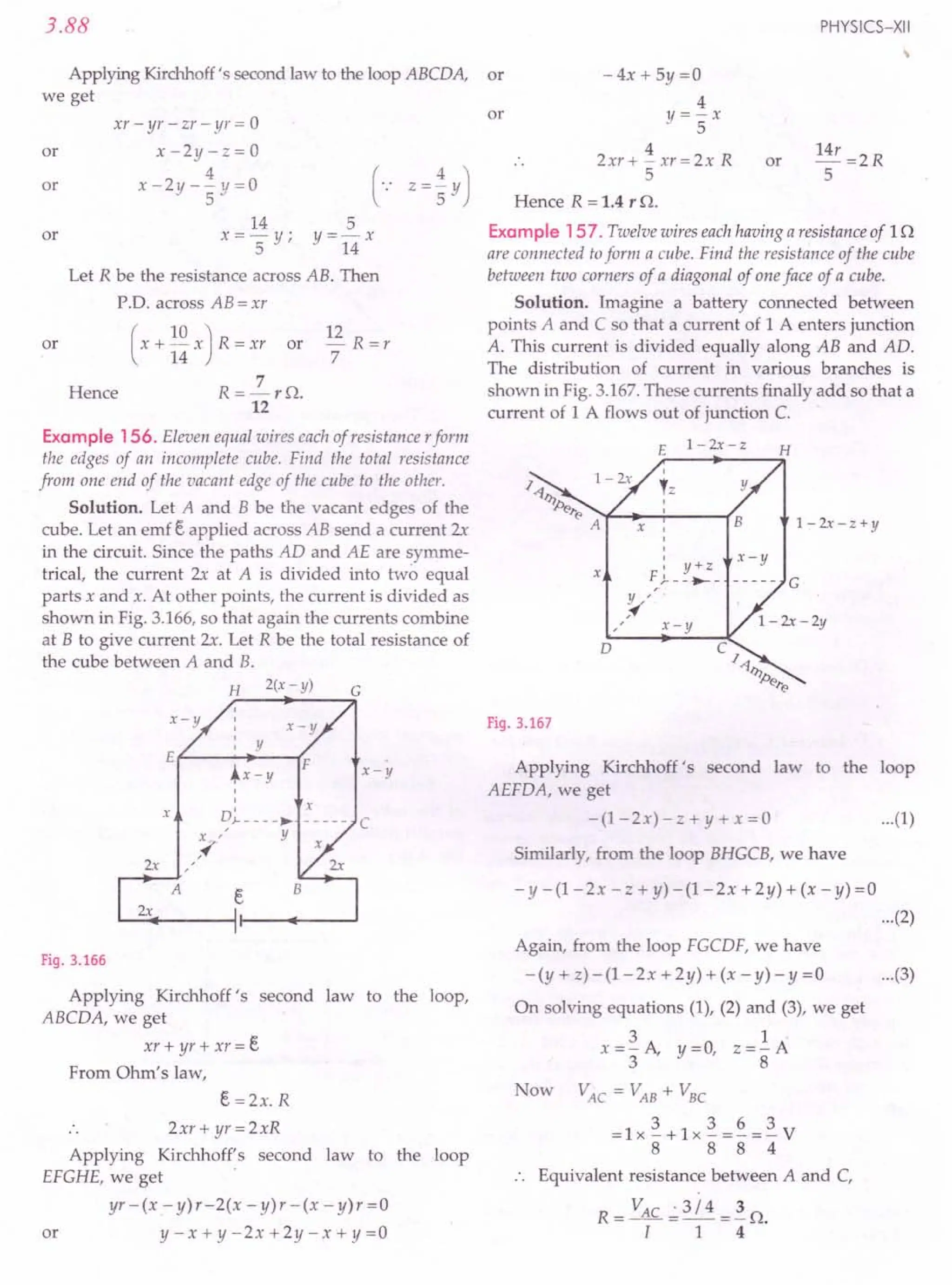
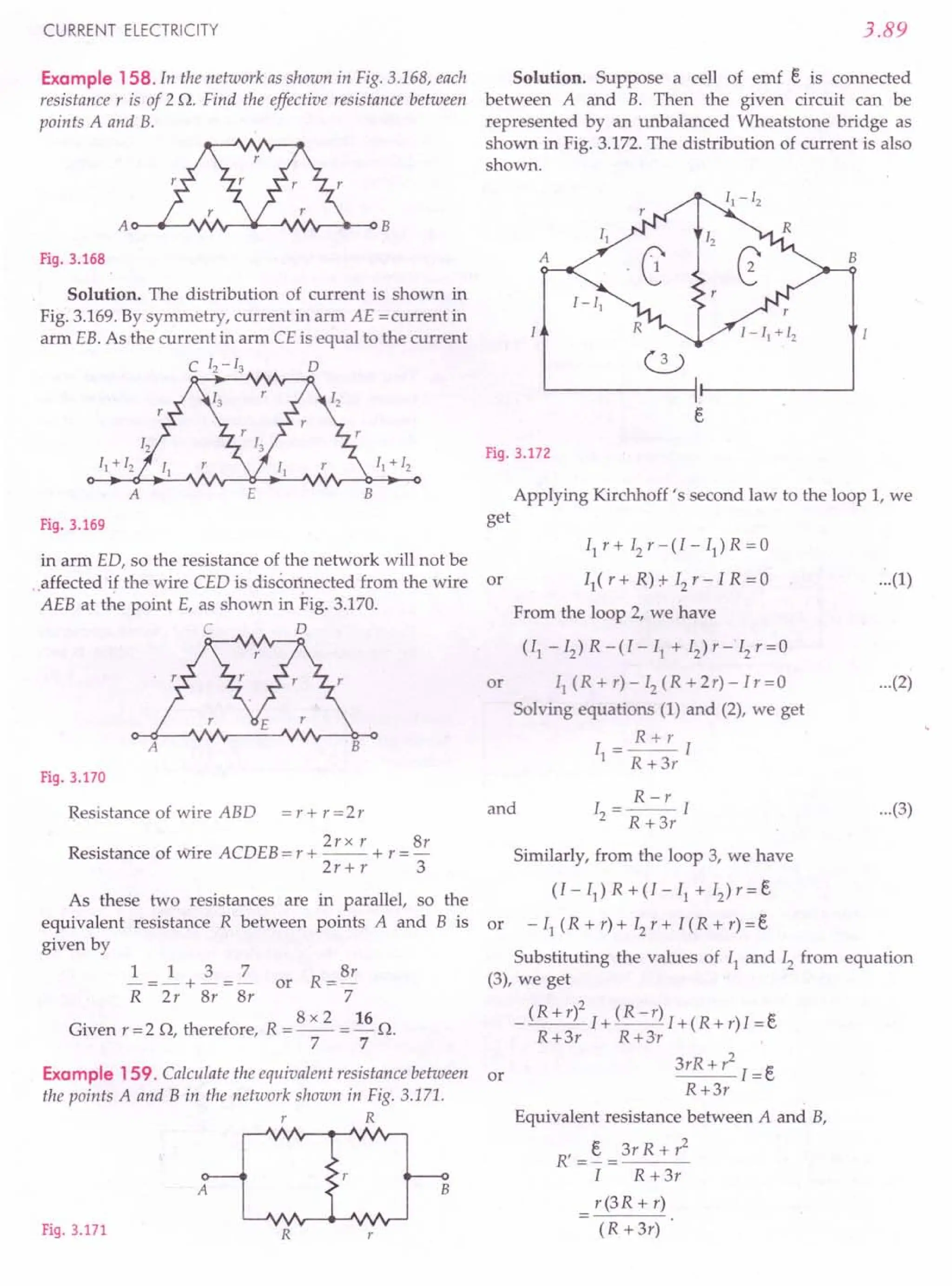
![3.90
j2)roblems ForPractice
1. Apply Kirchhoff's rules to the loops PRSP and
PRQP to write the expressions for the currents II' 12
and 13 in the circuit shown in Fig. 3.173.
[CBSE OD 10]
(
Ans. ~ A ---±- A II AJ
860 '215 '172
200n
Fig.3.173
60n
5V
LL- ...---H--.........J Q
4V
2. Use Kirchhoff's rules to determine the value of the
current 11 flowing in the circuit shown in Fig. 3.174.
[CBSE D 13C]
(Ans. I} ": 0.75 A)
30n h
11
13
20n 13
20V
a d
12
b c
g f 20n
e
80V
12
Fig.3.174
24V
11
3. Using Kirchhoff's
laws, determine the
currents II' 12 and 13
for the network shown 13
in Fig. 3.175.
[CBSE D 99C]
(Ans. 3 A, -1.5 A, 4.5 A) Fig.3.175
4. The circuit diagram shown in Fig. 3.176 has two
cells e} and e2
with emfs 4 V and 2 V respectively,
each one having an internal resistance of 2 Q. The
external resistance R is of 8Q. Find the magnitude
and direction of currents flowing through the two
cells. [ISCE 98]
(Ans. 11 = ~ A, 12 = - ~ AJ
27V 6n
4n
R
Fig.3.176
PHYSICS-XII
5. Fig. 3.177 shows n cells connected to form a series
circuit. Their internal resistances are related to their
emfs as Ii = a ei
, where a is a constant. Find (i) the
current through the circuit and (ii) the potential
difference between the terminals of ith battery.
[Ans. (i) J:. (ii) 0]
a
el '1 e2 '2 e3'3 en'n
L~~~--- ~:=J
Fig.3.177
6. Two cells of emfs 3 V and 4 V and internal resis-
tances 1Q and 2Q respectively are connected in
parallel so as to send current in the same direction
through an external resistance of 5Q.
(i) Draw the circuit diagram.
(ii) Using Kirchhoff's laws, calculate (a) the current
through each branch of the circuit. (b) p.d.
across the 5Q resistance. [CBSE OD 95, 96 C]
(Ans. (a) ~ A, ~ A, ~ A (b) 2.35vJ
17 17 17
7. In the electric network shown in Fig. 3.178, use
Kirchhoff's rules to calculate the power consumed
by the resistance R = 4 Q. [CBSE D 14C]
el
= 12V 'I = 2n (Ans. 9 W)
B I. C
II I'
II + 12 R=4n
A 0
E
e2~6 V
F
12 I'
Fig.3.178
8. A network of resistors is connected to a battery of
negligible internal resistance, as shown in Fig. 3.179.
Calculate the equivalent resistance between the
points A and D, and the value of the current 13
,
(Ans. 1.25Q, 0.5 A)
2 n 11
- 13
B c
2n
2n
I=2A
~---+-I f-----J
Fig.3.179](https://image.slidesharecdn.com/slaroraclass12thphysicsbyrockytrickster-250318042948-c8b51a5a/75/SL-ARORA-CLASS-12TH-PHYSICS-BY-ROCKY-TRICKSTER-pdf-275-2048.jpg)
![CURRENT ELECTRICITY
9. Using Kirchhoff's rules, determine the value of
unknown resistance R in the circuit shown in
Fig. 3.180 so that no current flows through 4Q
resistance. Also find the potential difference
between A and D. [CBSE D 12]
(Ans. 3 V)
F 1Q E o
R
1Q 4Q
r---I-:
B
9V 3V
A c
Fig.3.180
10. Find the current flowing through each cell in the
circuit shown in Fig. 3.181. Also calculate the
potential difference across the terminals of each
cell. (Ans. 0, - 3 A, 3 A, 3 V)
13V 1Q
Fig.3.181
11. In the network shown in Fig. 3.182,(i) calculate the
current of the 6 V battery and (ii) determine the
potential difference between the points A and B.
[Ans. (i) 2 A (ii) 4 Vj
A B
C 0
14V
4Q 12
4V II
B E
10V
6Q
4Q 13
6V
A F
2Q
Fig.3.183
2V
Fig.3.182
12. In the network shown in Fig. 3.183, find (i) the
currents II' 12 and 13 and (ii) the potential difference
between the points B and E.
[Ans. (i) II = 2 A, 12 = - 3 A, 13 = - 1A (ii) - 2 Vj
13. Calculate the potential difference between the
junctions Band D in the Wheatstone's bridge shown
in Fig. 3.184. [Roorkee 89] (Ans. 0.2 V)
3.91
B
o
e
2V
Fig.3.184
14. In the given electrical networks shown in
Figs. 3.185(a) and (b), identical cells each of emf t,
are giving same current 1. Find the values of the
resistors ~ and ~ in the network (b).
( Ans. 9.9Q, ~1Q)
Fig.3.185
15. What does the ammeter A read in the circuit
shown in Fig. 3.186? What if the positions of the
cell and the ammeter are interchanged ?
(Ans. ~A ~A)
11 '11
I
5V
40
2Q
Fig.3.186
E 50 B
16. In the circuit shown in
Fig. 3.187, determine 5Q 50
the current in the
resistance CD and C 0
equivalent resistance
between the points A 50 5Q
and B. The internal
resistance of cell is F
negligible.
(Ans. 7Q, 0.4 A) 14V
Fig.3.187](https://image.slidesharecdn.com/slaroraclass12thphysicsbyrockytrickster-250318042948-c8b51a5a/75/SL-ARORA-CLASS-12TH-PHYSICS-BY-ROCKY-TRICKSTER-pdf-276-2048.jpg)
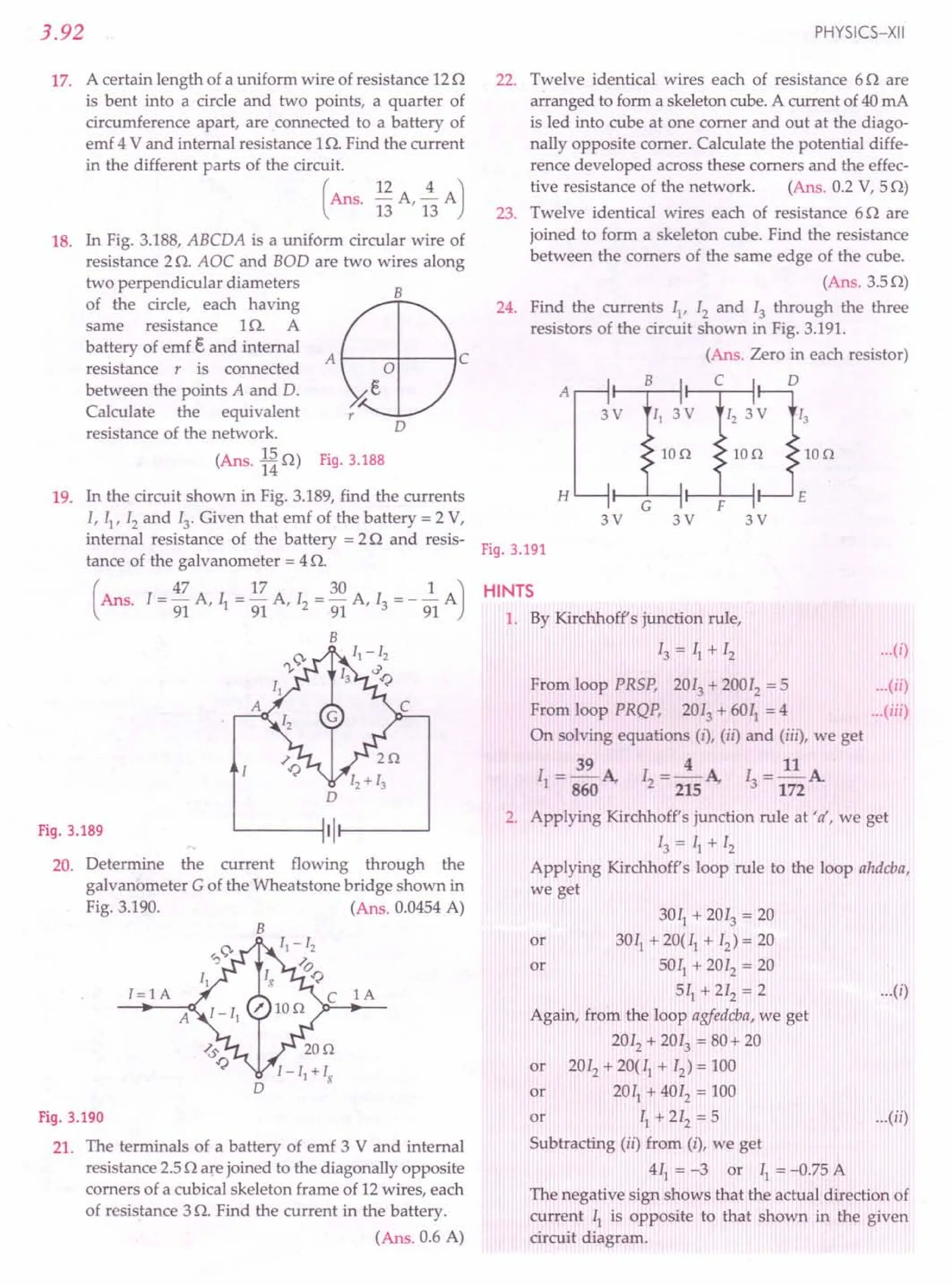
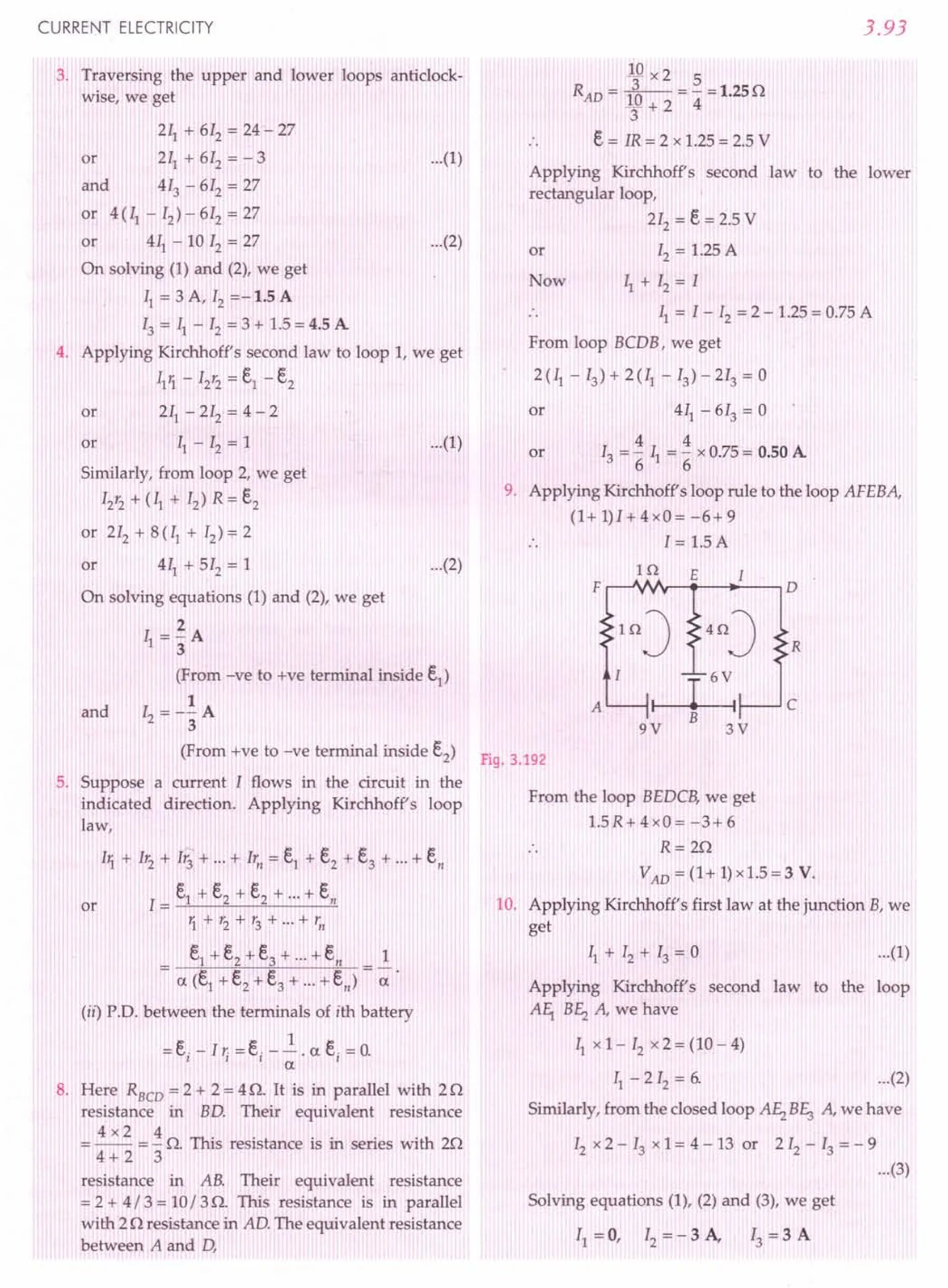
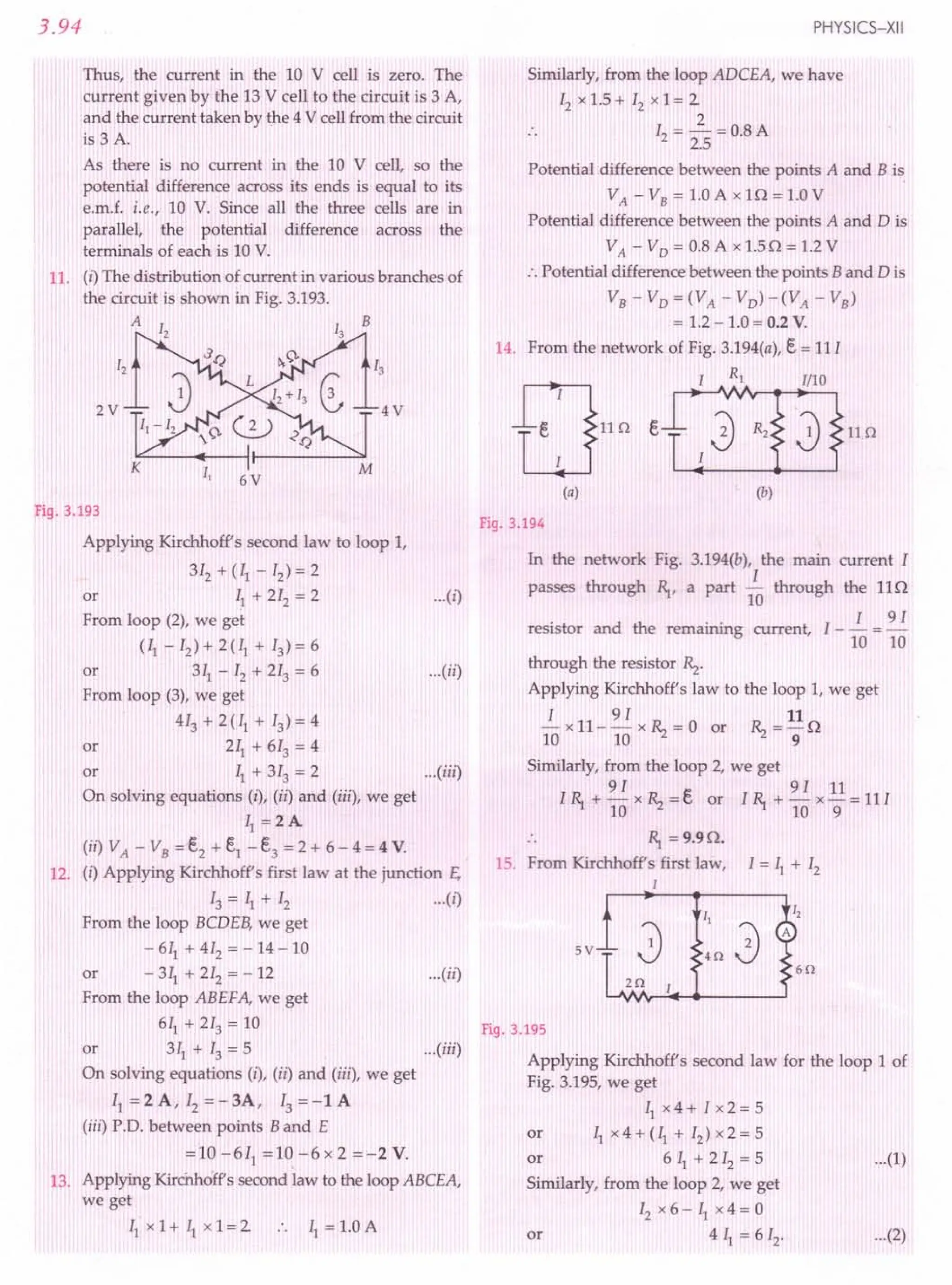
![CURRENT ELECTRICITY
Solving equations (1) and (2), 12= ~ A
11
This will be the reading of the ammeter.
On interchanging the cell and the ammeter, the
circuit takes the form as shown in Fig. 3.196. Again,
we can show that
5
12= 11 A.
5V
4Q
6Q
2Q
Fig. 3.196
16. Proceeding as in Example 151,we obtain equivalent
resistance between points A and B as
R' = 'Z R = 'Z x 5 = 70 [.: R = 50]
5 5
Main current,
I = ~ = 14 = 2 A
R 7
Current through 50 resistance in arm CD
321 1
= II - 12= "51- "5I = "5I ="5 x 2 = 0.4 A.
18. The current distribution is shown in Fig. 3.197.
B
r
D
Fig. 3.197
Applying Kirchhoff's law to different loops, we get
R(I-II)+ R(I-I2)+(R+r)I=e (1)
RII + R (II - 13)- R (I - II) = 0 (2)
RI3 - R (I2 - 13) - R (II - 13)= 0 (3)
RI2 - R (I - 12) + R (I2 - 13)= 0 (4)
On simplifying and solving these equations,
·27
11= 12, 13= '3 12, 1='3 12
7
and - 12r + 5 12R = e
3
3.95
If R' is the equivalent resistance of the network, then
l(r+R')=e
7 7
:. -12r+512
R=I(r+R')=-I2
(r+R')
3 3
R' = 15 R = 15 x 0.5 = 15 o.
7 7 14
or
19. Applying Kirchhoff's first law at the junction A,
I = II + 12 ...(i)
Applying Kirchhoff's second law to the loop ABDA,
we get
211+ 413 - 12= 0 ...(ii)
From the loop BCDB, we get
3(II -13)-2(I2 + 13)-413 =0
or 311- 212 - 913 = 0 ...(iii)
From the loop ABCEA, we get
211+ 3 (II - 13) + 2 (II + 12)= 2
or 711+212-313=2 ...(iv)
On solving equations (i), (ii) and (iii), we get
17 30 1
II = 91 A, 12= 91 A and 13= - 91 A
20. From the loop ABDA, we get
5~+101g-(I-II)15=0 [l=IA]
or 201I+lOIg=15
or 411 + 21g = 3 ...(i)
From the loop BCDB, we get
1O(II-1g)-20(1-1I + Ig)-10Ig=0
3011
- 401g = 20
or 311
- 41g = 2 ...(ii)
On solving equations (i) and (ii), we get
Ig = ~ A = 0.0454 A
22
21. Proceeding as in Example 154,we obtain the effective
resistance,
But R = 30, therefore,
R'=~ R
6
5x3
R=--=2.50
6
Total resistance of the circuit = 2.5 + 2.5 = 5.00
Current,
I = emf = 2 = 0.6 A.
total resistance 5.0
22. Proceeding as in Example 154, we obtain the
effective resistance, R' = ~ R
6
5x6
But R = 60, therefore, R' = -- = 50
6
P.D. developed = Resistance x Current
= 5 x(40 x 10-3) = 0.2 V.](https://image.slidesharecdn.com/slaroraclass12thphysicsbyrockytrickster-250318042948-c8b51a5a/75/SL-ARORA-CLASS-12TH-PHYSICS-BY-ROCKY-TRICKSTER-pdf-280-2048.jpg)
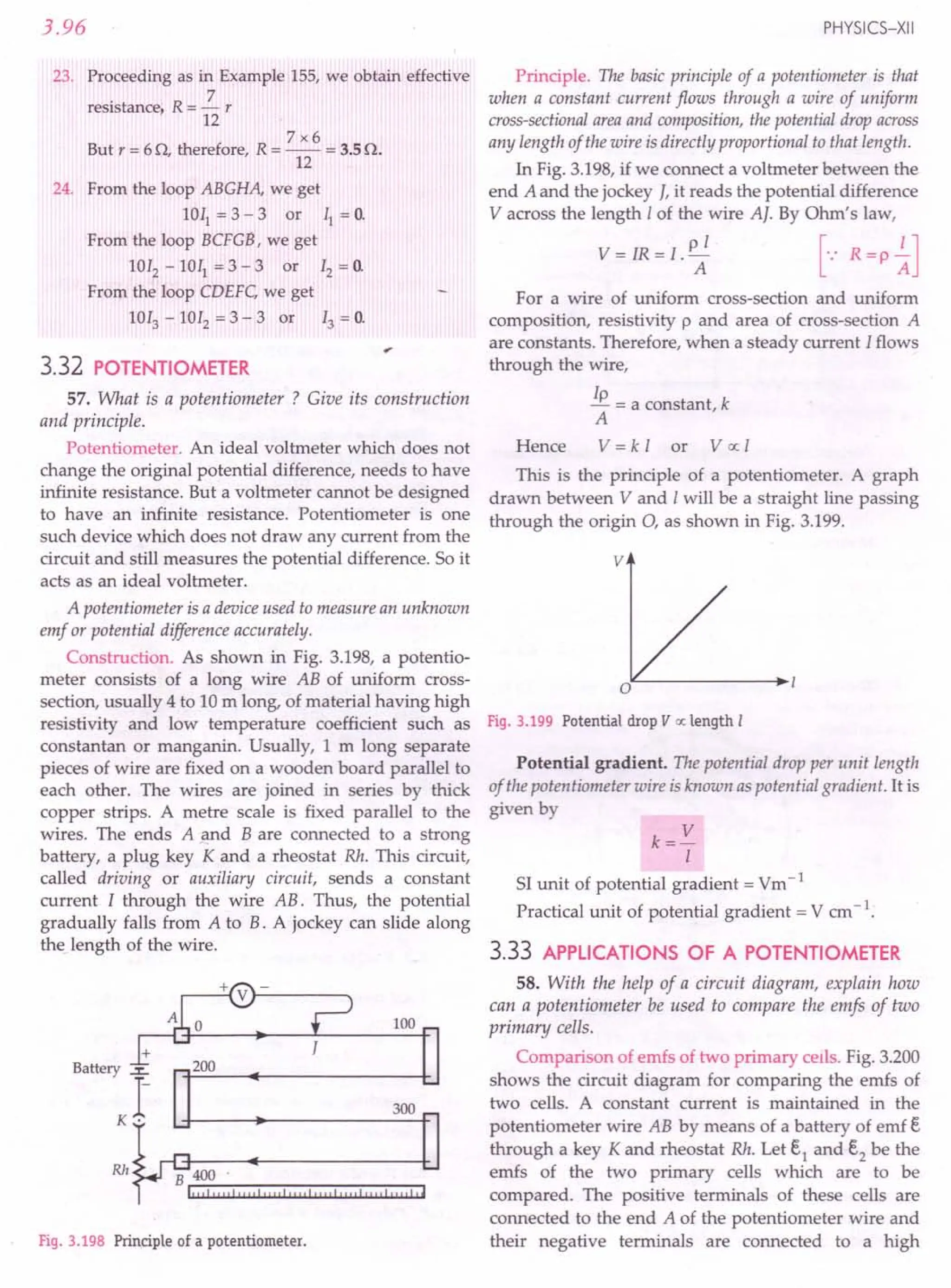
![CURRENT ELECTRICITY
resistance box RB., a galvanometer G and a jockey I
through a two way key. A high resistance R is inserted
in the circuit from resistance box R.B. to prevent
excessive currents flowing through the galvanometer.
Fig. 3.200 Comparing emfs of two cells by a
potentiometer.
As the plug is inserted between a and c, the cell i
gets introduced in the circuit. The jockey I is moved
along the wire AB till the galvanometer shows no
deflection. Let the position of the jockey be I] and
length of wire AI1 = 11
,If k is the potential gradient
along the wire AB, then at null point,
E,1 = kl]
By inserting the plug between b and c,the null point
is again obtained for cell E,2' Let the balancing length be
AI2 = 12
, Then
Hence,
E,2 = kl2
E,2 12
E,] = T;
If one of the two cells is a standard cell of known
emf, then emf of the other cell can be determined.
~ _ 12 ~
c.
2
- -. c.
1
11
In order to get the null point on the potentiometer or
wire, it is necessary that the emf, E, of the auxiliary
battery must be greater than both E,1 and E,2'
59. With the help of a circuit diagram, explain how
can a potentiometer be used to measure the internal
resistance of a primary cell.
Internal resistance of a primary cell by a
potentiometer. As shown in the Fig. 3.201, the +ve
terminal of the cell of emf E, whose internal resistance r
is to be measured is connected to the end A of the
potentiometer wire and its negative terminal to a
galvanometer G and jockey J. A resistance box RB. is
connected across the cell through a key Kz.
3.97
+
Battery ~
1-
K1 •
Rh B
Fig. 3.201 To determine the internal resistance
of a cell by a potentiometer.
Close the key K1
. A constant current flows through
the potentiometer wire. With key Kz kept open, move
the jockey along ABtill it balances the emf E, of the cell.
Let 11 be the balancing length of the wire. If k is the
potential gradient, then emf of the cell will be
E, = kl1
With the help of resistance box RB., introduce a
resistance R and close key Kz. Find the balance point
for the terminal potential difference V of the cell. If 12is
the balancing length, then
V= kl2
E, _ 11
V Zz
Let r be the internal resistance of the cell. If current I
flows through cell when it is shunted with resistance
R, then from Ohm's law we get
E, = I (R + r) and V = IR
~= R+r =ll
V R 12
r I
1+-=~
R 12
L = 11-12
R 12
.'. Internal resistance,
[
1 -I ]
r e=R y .
60. Why is a potentiometer preferred over a voltmeter
for measuring the emf of a cell ?
Superiority of a potentiometer to a voltmeter.
Potentiometer is a null method device. At null point, it
does not draw any current from the cell and thus there
is no potential drop due to the internal resistance of the
cell. It measures the p.d. in an open circuit which is
equal to the actual emf of the cell.](https://image.slidesharecdn.com/slaroraclass12thphysicsbyrockytrickster-250318042948-c8b51a5a/75/SL-ARORA-CLASS-12TH-PHYSICS-BY-ROCKY-TRICKSTER-pdf-282-2048.jpg)
![3.98
On the other hand, a voltmeter draws a small
current from the cell for its operation. So it measures
the terminal p.d. in a closed circuit which is less than the
emf of a cell. That is why a potentiometer is preferred
over a voltmeter for measuring the emf of a cell.
3.34 SENSITIVENESS OF A POTENTIOMETER
61. What do you mean by the sensitivity of a
potentiometer? How can we increase the sensitivity of a
potentiometer?
Sensitivity of a potentiometer. A potentiometer is
sensitive if
(i) it is capable of measuring very small potential
differences, and
(ii) it shows a significant change in balancing length for
asmallchangein thepotentialdifferencebeingmeasured.
The sensitivity of a potentiometer depends on the
potential gradient along its wire. Smaller the potential
gradient, greater will be the sensitivity of the potentiometer.
The sensitivity of a potentiometer can be increased
by reducing the potential gradient. This can be done in
two ways:
(i) For a given potential difference, the sensitivity
can be increased by increasing the length of the
potentiometer wire.
(ii) For a potentiometer wire of fixed length, the
potential gradient can be decreased by reducing
the current in the circuit with the help of a rheostat.
For Your Knowledge
~ A potentiometer can be regarded as an ideal voltmeter
with infinite resistance because it does not draw any
current from the source of emf at the null point.
~ The principle of potentiometer requires that (i) the
potentiometer wire should be of uniform cross-
section and (ii) the current through the wire should
remain constant.
~ The emf of the auxiliary battery must be greater than
the emf of the cell to be measured.
~ The balance point cannot be obtained on the potentio-
meter if the fall of potential along the potentiometer
wire due to the auxiliary battery is less than the emf of
the cell to be measured.
~ The positive terminals of the auxiliary battery and the
cell whose emf is to be determined must be connected
to the zero end of the potentiometer.
~ Other uses of a potentiometer. Any physical quantity
that can produce or control a potential difference can
be measured using a potentiometer. Thus, a potentio-
meter can be used to measure and control stress,
temperature, radiation, pH, frequency, etc.
PHYSICS-XII
Formulae Used
e I
1. For comparing emfs of two cells, e2 =..1.
1 ~
2. For measuring internal resistance of a cell,
r = ~ -12 x R
Lz
3. Potential gradient of the potentiometer wire,
k= V
I
4. Unknown emf balanced against length I, e = k I
Units Used
The emfs e1
and e2
are in volt, lengths ~ and 12 of
potentiometer wire in metre.
Example 160. A potentiometer wire is 10 mlong and has a
resistance of18 Q. It is connected to a battery of emf5 Vand
internal resistance 2 Q. Calculate the potential gradient
along the wire.
Solution. Here 1=10 m, R =18 Q, e = 5 V, r=2 Q
Current through the potentiometer wire,
1= _e_ =_5_ =2. =.!. A
R + r 18 +2 20 4
:. Potential gradient = IR =.!. x 18 = 0.45 Vrn -1.
1410
Example 161 . A potentiometer wire is supplied a constant
voltage of 3 V. A cell of emf108 V is balanced by the voltage
drop across 216 em of the wire. Find the total length of the
potentiometer wire.
Solution. Here e =3 v.s, =1.08 V, 11 =216 ern, I =?
e I e 3 x 216
As e
1
= z; .'.1= e
1
x 11= 108= 600 em.
Example 162. Two cells of emfs e1 and e2 (e1 > e2) are
connected as shown in Fig. 3.202.
~~~
e, e,
Fig. 3.202
When a potentiometer is connected between A and B, the
balancing length of the potentiometer wire is 300 em. On
connecting the same potentiometer between A and C, the
balancing length is 100 em.Calculate the ratio of e1 and e2.
[CBSE D94]](https://image.slidesharecdn.com/slaroraclass12thphysicsbyrockytrickster-250318042948-c8b51a5a/75/SL-ARORA-CLASS-12TH-PHYSICS-BY-ROCKY-TRICKSTER-pdf-283-2048.jpg)
![The sensitivity of a potentiometer wire can be AO-----------.-----O
increased by decreasing potential gradient either
through increasing length of the potentiometer wire or
through increasing resistance put in series with the
main cell. Fig. 3.205
CURRENT ELECTRICITY
Solution. As emf a: balancing length of the
potentiometer wire
.'. When the potentiometer is connected between
A and B, E.1o; 300
When potentiometer is connected between A and C,
E.1- E.2o: 100
E.1- E.2_ 100
Hence -E.-
1
-- 300
E.2 1 2
-=1--=-
E.1 3 3
or
E. 3
or ~---3' 2
E.2- 2 - ..
Example 163. In Fig. 3.203, a long uniform potentiometer
wire AB is having a constant potential gradient along its
length. The null points for the two primary cells of emfs E.1
and E.2connected in the manner shown are obtained at a
distance of 120 em and 300 cmfrom the end A. Find (i)e1 / e2
and (ii) position of null point for the cell E.1
.
How is the sensitivity of a potentiometer increased?
[CBSE D 12]
t---- 300ern
120 ern 1
A B
Fig. 3.203
Solution. (i) Let k be the potential gradient in
volt/ern. Then
E.1+E.2= 300k
e1
= 210k
e1
_ 7
e2
- 3
(ii) As E.1= 210k
.'. Balancing length for cell E.1is
E.
11 =~=210 em
k
and e1 -E.2 =120k
and E.2= 90k
Hence,
3.99
Example 164. In a potentiometer, a standard cell of emf
5 V and of negligible resistance maintains a steady current
through the potentiometer wire of length 5 m Two primary
cells of emfs E.1and E.2are joined in series with (i) same
polarity, and (ii) opposite polarity. The combination is
connected through a galvanometer and a jockey to the
potentiometer. The balancing lengths in the two cases are
found to be 350 em and 50 em respectively.
(i) Draw the necessary circuit diagram.
(ii) Find the value of the emjs of the two cells.
[CBSE D 04C)
Solution. (i) The circuit diagram is shown in
Fig. 3.204.
E.=5V
I----{.
A
Q----,---~B
Fig. 3.204
(ii) Here k = 5 V = 5 V = _1_ V cm-1
5 m 500 em 100
In first case,
1
E.1+ E.2= kl1 =- x 350
100
or E.1+ E.2= 3.50 V ...(i)
In second case,
1
E.1-E.2 = kI2 =- x 50 =0.50 V ...(ii)
100
On solving (i) and (ii), we get
E.1= 2.0 V and e2 = 1.50 V.
Example 165. A 10 metre long wire of uniform
cross-section of 200 resistance is used as a potentiometer
wire. This wire is connected in series with a battery of 5 V,
along with an external resistance of 480 o. If an unknown
emf E. is balanced at 600 em of this wire, calculate (i) the
potential gradient of the potentiometer wire and (ii) the
value of the unknown emfe. [CBSE D 06]
5V 480Q
II R
]
600 ern ~I
B
E.](https://image.slidesharecdn.com/slaroraclass12thphysicsbyrockytrickster-250318042948-c8b51a5a/75/SL-ARORA-CLASS-12TH-PHYSICS-BY-ROCKY-TRICKSTER-pdf-284-2048.jpg)
![3.100
Solution. Current in
potentiometer wire is
1= V
RAB + R
the circuit or through the
5 V =0.01 A
(20 + 480)0
Resistance of potentiometer wire,
RAB =200
.'. PD. across the wire,
V = ll'AB =0.01 x 20 =O.~ V
Length of potentiometer wire,
1= 10 m =1,000 em
:. Potential gradient,
k = V = 0.2 V =0.0002 V cm-1
I 1,000 ern
Unknown emf balanced against 600 cm length is
E, = kl' = 0.0002 x 600 = 0.12 V.
Example 166. In the circuit diagram given below, AB is a
uniform wire of resistance 15 ohm and length one metre. It is or
connected to a series arrangement of cell E,1
of emf2.0 Vand
negligible internal resistance and a resistor R. Terminal A is
also connected to an electrochemical cell E,2of emf 75 m V
and a galvanometer G. In E,
this set-up, a balancing ..--~ rl --~'VIr----,
point is obtained at 30 em
mark from A. Calculate the A ~----r-----<l B
resistance of R. If E,2were
to have an emf of300 mV,
where will you expect the
balancing point to be ?
[CBSE D 99C]
Fig. 3.206
Solution. Current through the potentiometer wire,
1= E,1 _2_
R + RAB R + 15
Resistance of the 30 em length of wire, which
balances the emf E,2'is
R' = ~ x 30 = 4.5 0
100
Now, E,2= Potential drop across R'
75 x 10-3 = _2_ x 4.5
R +15
R = 2 x 4.5 _ 15 = 120 - 15 = 105 O.
75 x 10-3
or
For E,2= 300 m V, the balancing length is given by
E,2 300
12 = e .11 = - x 30 = 120 em
(;1 75
As the length of the potentiometer wire is just
100 em, so this balance point cannot be obtained on the
wire.
PHYSICS-XII
Example 167. The length of a potentiometer wire is 5 m It
is connected to a battery of constant emf For a given
Leclanche cell, the position of zero galvanometer deflection is
obtained at 100 em If the length of the potentiometer wire be
made 8 m instead of 5 m, calculate the length of wire for zero
deflection in the galvanometer for the same cell.
[CBSE F 97]
Solution. Here I = 5 m, 11 = 100 cm = 1 m, l' = 8 m,
I~=?
Let E, be the emf of the Leclanche cell.
In first case, E, = IR 11
I
E, = IR/~
l'
...(1)
In second case, ...(2)
Comparing equations (1) and (2),
!l=ll
l' I
, 11 , 1
11 = - x I = - x 8 = 1.6 m.
I 5
Example 168. A potentiometer wire of length 100 em has
a resistance of 10 O. It is connected in series with a
resistance and a battery of emf 2 V and of negligible internal
resistance. A source of emf 10 mV is balanced against a
length of 40 em of the potentiometer wire. What is the value
of the external resistance? [lIT]
Solution. Fig. 3.207 shows a potentiometer wire of
length 100 em connected in series to a cell of emf 2 V
and an unknown resistance R. The cell of emf 10 mV
balances length A] = 40 cm of the wire.
R 2V
A~---7r-------6B
lOmV
Fig. 3.207
Resistance of wire Al = ~ x 40 = 4 0
100
Current through wire AI,
1= 10 m V = 10 x 10-
3
V = 2.5 x 10⁻³ A
40 40
The same current flows through the potentio-
meter wire and through the external resistance R.
Total resistance = (R + 10) 0](https://image.slidesharecdn.com/slaroraclass12thphysicsbyrockytrickster-250318042948-c8b51a5a/75/SL-ARORA-CLASS-12TH-PHYSICS-BY-ROCKY-TRICKSTER-pdf-285-2048.jpg)
![CURRENT ELECTRICITY
or
2.5 x 10⁻³ A = 2 V
(R + 10)0
2
R+I0= =BOO
2.5 x 10⁻³
R = BOO -10 = 790 O.
Example 169. AB is 1 metre long uniform wire of 100
resistance. Other data are as shown in Fig. 3.20B. Calculate
(i) potential-gradient along AB and (ii) length AO, when
galvanometer shows no deflection. [CBSE D 2000q
Fig. 3.208
Solution. (i) Total resistance of the primary circuit
= 15+ 10=250, emf = 2 V
:.Current in the wire AB,
I = 3..- =0.08 A
25
P.D. across the wire AB
= Current x resistance of wire AB
= 0.08 x 10 =O.B V
Potential gradient
= P.D. =~=0.008Vem-l.
length 100
(ii) Resistance of secondary circuit
=12 +0.3 =1.50
emf =1.5 V
Current in the secondary circuit = 1.5 = 1.0A
1.5
The same is the current in 0.3 0 resistor.
P'D. between points A and 0
= P.D. across 0.30 resistor in the
zero-deflection condition
= Current x resistance
= 1.0x 0.3 =0.3 V
Length AO
Potential difference
Potential gradient
0.3 V
-----0-1
= 37.5 em.
O.OOB V em"
3.101
Example 170. A cell gives a balance with 85 em of a
potentiometer wire. When the terminals of the cell are
shorted through a resistance of7.5 0, the balance is obtained
at 75 em Find the internal resistance of the cell. [ISCE 951
Solution. Here 11= 85 em, 12= 75 em, R = 7.5 0
Internal resistance,
r = R (/1 -12) =7.5 (85 -75) = 10.
12 75
Example 171. When a resistor of 50 is connected across
cell, its terminal p.d. is balanced by 150 em of potentiometer
wire and when a resistor of 100 resistance is connected
across the cell, the terminal p.d. is balanced by 175 em of the
potentiometer wire. Find the internal resistance of the cell.
Solution. In the first case, r = Rl ( I~
11
J
I
r _1 = 1-11 ...(1)
Rl
In the second case,
r= RzC ~212
J
I
r-.L=1-1
2
Rz
Subtracting (2) from (1),
r[ ~1 - ~]=I-II-I+12
r= 12-11 = 175 -150 = 25 =20
~ _.!L 150 _ 175 12.5 .
Rl Rz 5 10
~roblems For Practice
...(2)
1. A potentiometer wire is 10 m long and a potential
difference of 6 V is maintained between its ends.
Find the emf of a cell which balances against a
length of 180 em of the potentiometer wire.
(Ans. 1.08 V)
2. The resistance of a potentiometer wire of length
10 m is 20O. A resistance box and a 2 volt
accumulator are connected in series with it. What
resistance should be introduced in the box to have a
potential drop of one microvolt per millimetre of
the potentiometer wire? [Kerala 94)
(Ans. 39800)
3. In a potentiometer arrangement, a cell of emf
1.20volt gives a balance point at 30 cm length of the
wire. This cell is now replaced by another cell of
unknown emf. If the ratio of the emfs of the two](https://image.slidesharecdn.com/slaroraclass12thphysicsbyrockytrickster-250318042948-c8b51a5a/75/SL-ARORA-CLASS-12TH-PHYSICS-BY-ROCKY-TRICKSTER-pdf-286-2048.jpg)
![3.102
cells is 1.5, calculate the difference in the balancing
length of the potentiometer wire in the two cases.
[CBSE D 06C] (Ans. 10 em)
4. Two cells of emfs e1
and e2
are connected together
in two ways shown here. The 'balance points' in a
given potentiometer experiment for these two com-
binations of cells are found to be at 351.0 em and
70.2em respectively. Calculate the ratio of the emfs
of the two cells. [CBSE Sample Paper 08] (Ans. 3 : 2)
5. A potentiometer has 400 em long wire which is
connected to an auxiliary of steady voltage 4 V. A
Leclanche cell gives null point at 140em and Daniel
cell at 100 cm. (i) Compare emfs of the two cells.
(ii) If the length of wire is increased by 100ern, find
the position of the null point with the first cell.
[Ans. (i) 7 : 5, (ii) 175 em]
6. With a certain cell, the balance point is obtained at
60 cm from the zero end of the potentiometer wire.
With another cellwhose emf differs from that of the
first cell by 0.1 V, the balance point is obtained at
55 ern mark. Calculate the emf of the two cells.
(Ans. 1.2 V, 1.1 V)
7. A potentiometer wire has a potential gradient of
0.0025volt/em along its length. Calculate the length
of the wire at which null-point is obtained for a
1.025 volt standard cell. Also, find the emf of
another cell for which the null-point is obtained at
860 cm length. (Ans. 410 em, 2.15 V)
8. AB is a potentiometer wire of length 100 em. When
a cell e2
is connected across AC, where AC = 75em,
no current flows from e2
. Find (I) the potential
gradient along AB and (ii) emf of the cell e2
. The
internal resistance of the cell e1
is negligible.
[Ans. (i) 0.02 volt/ern (ii) 1.5 V]
+ -
ACf-------~:::..--4:l B
Fig. 3.209
9. A cell can be balanced against 110ern and 100em of
potentiometer wire respectively when in open circuit
and in circuit shorted through a resistance of 10O.
Find the internal resistance of the cell. (Ans. 10)
10. A potentiometer wire of length 1 m has a resistance
of 10O. It is connected to a 6 Vbattery in series with
a resistance of 5O. Determine the emf of the
primary cell which gives a balance point at 40 em.
[CBSE D 14]
(Ans. 1.6 V)
PHYSICS-XII
11. A standard cell of emf 1.08 V is balanced by the
potential difference across 91 cm of a metre long
wire supplied by a cell of emf 2 V through a series
resistor of resistance 2O. The internal resistance of
the cell is zero. Find the resistance per unit length of
the potentiometer wire. (Ans. 0.030 em-I)
12. Potentiometer wire PQof 1m length is connected to
a standard cell e1
. Another cell,e2
, of emf 1.02V is
connected as shown in the circuit diagram with a
resistance 'r' and a switch,S. With switch 5 open,
null position is obtained at a distance of 51 em from
P. Calculate (i) potential gradient of the potentio-
meter wire and (ii) emf of the cell e1
. (iii) When
switch 5is closed, will null point move towards Por
towards Q? Give reason. [CBSE OD 04]
(Ans. 0.02V em- 2 V, no effect)
P~------------.---~Q
Fig. 3.210
13. A battery e1
of 4 V and a variable resistance Rh are
connected in series with the wire AB of the
potentiometer. The length of the wire of the
potentiometer is 1 metre. When a cell e2
of emf
1.5 volt is connected between points A and C, no
current flows through e2
. Length of AC = 60em.
(i) Find the potential difference between the ends
A and Bof the potentiometer.
(ii) Would the method work, if the battery e1
is
replaced by a cell of emf of 1 V ?
[CBSE D 03]
[Ans. (i) 2.5 V, (ii) No]
Rh
4V
~-----100cm-----~
C
A~------------~------~B
Fig. 3.211
14. The potentiometer wire of length 200em has a
resistance of 20O. It is connected in series with a
resistance 100 and an accumulator of emf 6 V](https://image.slidesharecdn.com/slaroraclass12thphysicsbyrockytrickster-250318042948-c8b51a5a/75/SL-ARORA-CLASS-12TH-PHYSICS-BY-ROCKY-TRICKSTER-pdf-287-2048.jpg)
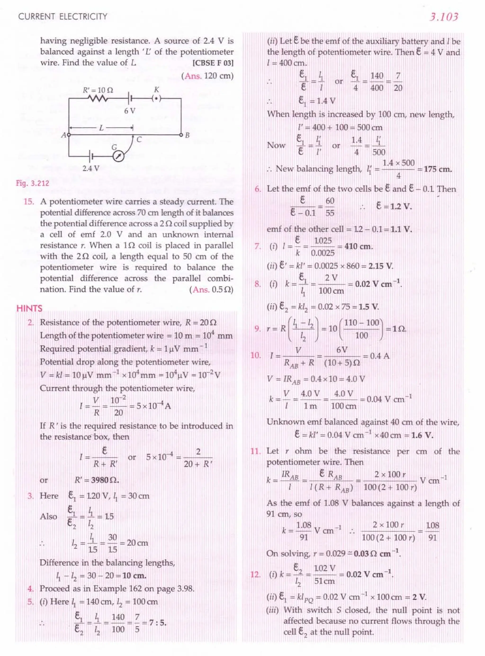
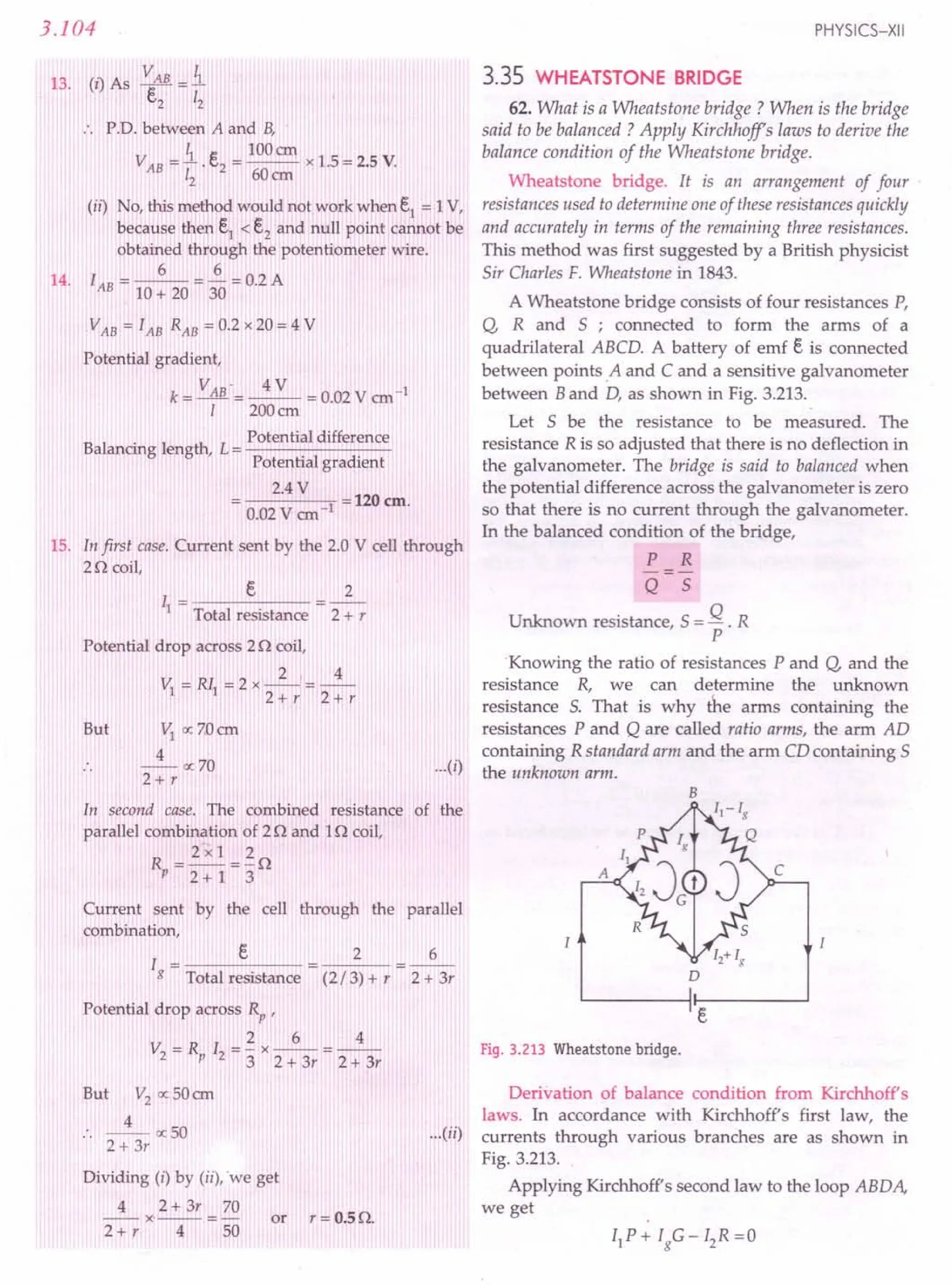
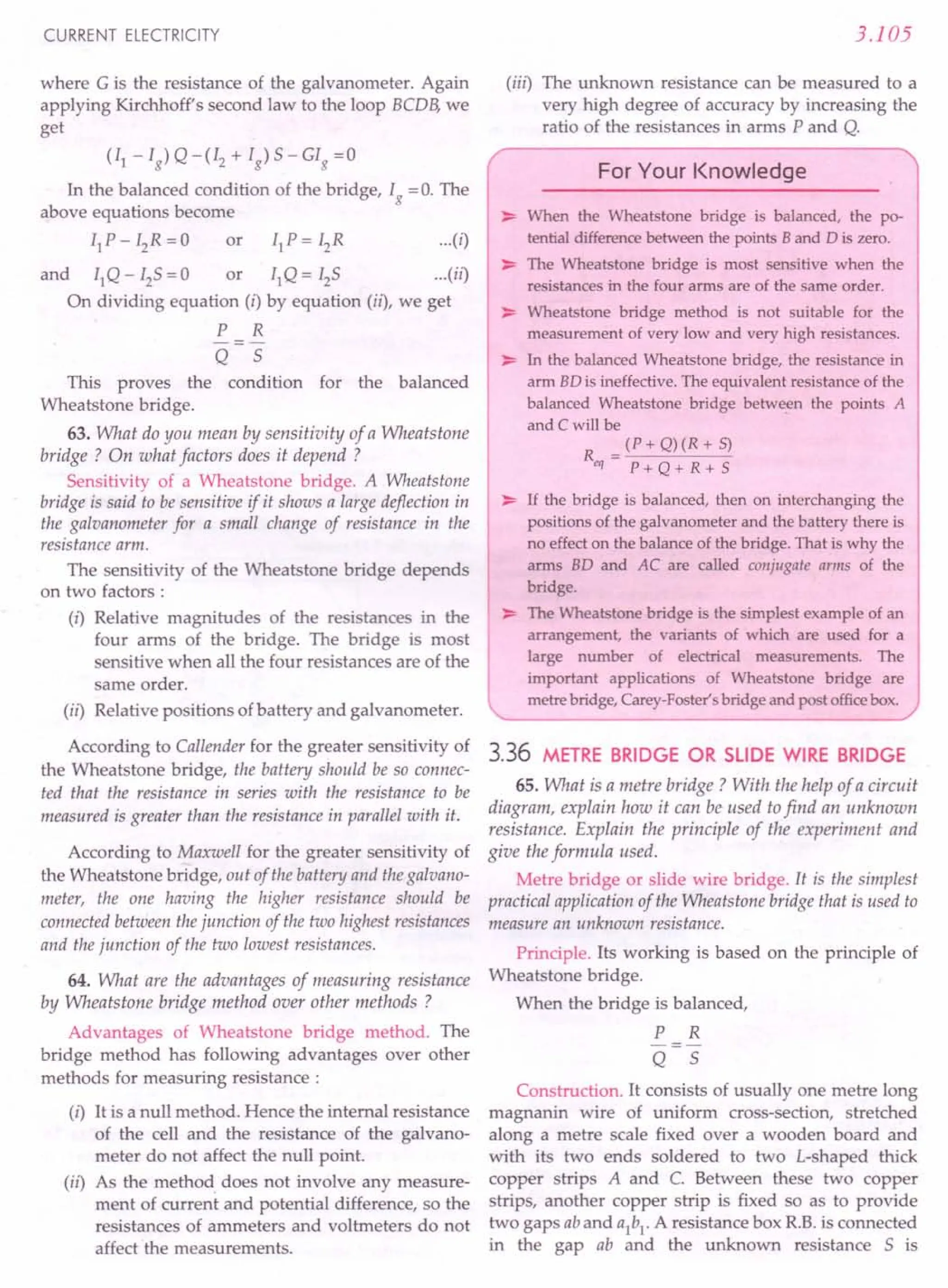
![3.106
connected in the gap a1
b1
. A source of emf e is
connected across AC. A movable jockey and a
galvanometer are connected across BO, as shown in
Fig. 3.214.
K
.-----~------+~II~--~(·r-~r-----~
s
C
Fig. 3.214 Measurement of unknown resistance
by a metre bridge.
Working. After taking out a suitable resistance R
from the resistance box, the jockey is moved along the
wire AC till there is no deflection in the galvanometer.
This is the balanced condition of the Wheatstone
bridge. If P and Q are the resistances of the parts AB
and BC of the wire, then for the balanced condition of
the bridge, we have
P R
-=-
Q 5
Let total length of wire AC = 100 em and AB = I em,
then BC = (100-I) cm. Since the bridge wire is of
uniform cross-section, therefore,
resistance of wire ex length of wire
P resistance of AB
Q resistance of BC
or
cr I I
o (100-I) 100 -I
where o is the resistance per unit length of the wire.
Hence
or
R I
5 100-1
~ = R (1~0-I)
Knowing I and R, unknown resistance 5 can be
determined.
Determination of resistivity. If ris the radius of the
wire and I' its length, then resistivity of its material
will be .
SA 5x 1t?
P=-1-'=--1'-.
PHYSICS-XII
E I B d
•
(i) Wheatstone Bridge'
(ii) Slide Wire Bridge
Formulae Used
1. For a balanced Wheatstone bridge, !.. = 13.
Q 5
If X is the unknown resistance
!.. = B. or X = RQ
Q X p.
2. In a slide wire bridge, if balance point is obtained
at 1 em from the zero end, then
!.. = B. = _1_ or X = (100
1
- I) R
Q X 100-1
Units Used
All resistances are in ohm and distances in em.
Example 172. Find out the magnitude of resistance X in
the circuit shown in Fig. 3.215, when no current flows
through the 5 Q resistor. [ISCE 98]
6V
x 18n
Fig. 3.215
Solution. As no current flows through the middle
5 Q resistor, the circuit represents a balanced Wheat-
stone bridge.
X 2
18 6
2
or X = - x 18 = 6 Q.
6
Example 173. P, Q, Rand 5 arefour resistance wires of
resistances 2, 2, 2 and 3 ohms respectively. Find out the
resistance with which 5 must beshunted in order that bridge
may be balanced.
Solution. For a balanced Wheatstone bridge,
P R
-=-
Q 5
But P=2Q, Q=2Q, R=2Q .. ~=~
2 5
i.e., resistance 5 must have a total resistance of 2 Q. In
arm 5, the resistance of 3Q must be shunted with a
resistance r so that the combined resistance is of 2 Q.
1111111
i.e., - + - = - or - = - - - =-
r32 r236
:. Required shunt, r = 6Q.](https://image.slidesharecdn.com/slaroraclass12thphysicsbyrockytrickster-250318042948-c8b51a5a/75/SL-ARORA-CLASS-12TH-PHYSICS-BY-ROCKY-TRICKSTER-pdf-291-2048.jpg)
![CURRENT ELECTRICITY
Example 174. In a Wheatstone bridge arrangement, the
ratio arms P and Q are nearly equal. The bridge is balanced
when R = 500 O. On interchanging P and Q, the value ofR
for balancing is 505 O. Find the value of X and the ratio
PIQ.
Solution. For balanced Wheatstone bridge,
P R
-=-
Q X
In the first case, R = 500 0
P 500
-=-
Q X
In the second case when P and Q are interchanged,
R =5050
Q = 505
P X
Multiplying equations (1) and (2),
1 = 500 x 505
X2
or X = ~500 x 505
= 502.50
Substituting the value of X in (1), we get
P 500
-=--
Q 502.5
=_1_=1: 1.005
1.005
Example 175. The galvanometer, in each of the two given
circuits, does not show any deflection. Find the ratio of the
resistors Rl and ~, used in these two circuits.
[CBSEOD 13]
3.0V 1.20n
~----~Gr-----~
Circuit 1 Circuit 2
Fig. 3.216
Solution. In circuit 1, the Wheatstone bridge is in
the balanced condition, so
4 6
-- = - :::>
Rl 9
3.107
In circuit 2, the interchange of the positions of the
battery and the galvanometer does not affect the
balance condition of the Wheatstone bridge, so
~=~
12 8
~ = 6x8 =40
12
...(1)
~=~=~
~ 4 2
= 3: 2
Example 176. Calculate the current drawn from the
battery by the network of resistors shown in Fig. 3.217.
rCBSE OD 09, ISC]
...(2) 2n
2n
4V
Fig. 3.217
Solution. The given network is equivalent to the
circuit shown in Fig. 3.218.
• B
D
4V
Fig. 3.218
Now
10 20
---
20 40
i.e.,
P R
-=-
Q 5
The given circuit is a balanced Wheatstone bridge.
The resistance of 50 in arm BD is ineffective. The
equivalent circuit reduces to the circuit shown in
Fig. 3.219.
In B zn
c
z o D 4n
4V
I
Fig. 3.219](https://image.slidesharecdn.com/slaroraclass12thphysicsbyrockytrickster-250318042948-c8b51a5a/75/SL-ARORA-CLASS-12TH-PHYSICS-BY-ROCKY-TRICKSTER-pdf-292-2048.jpg)
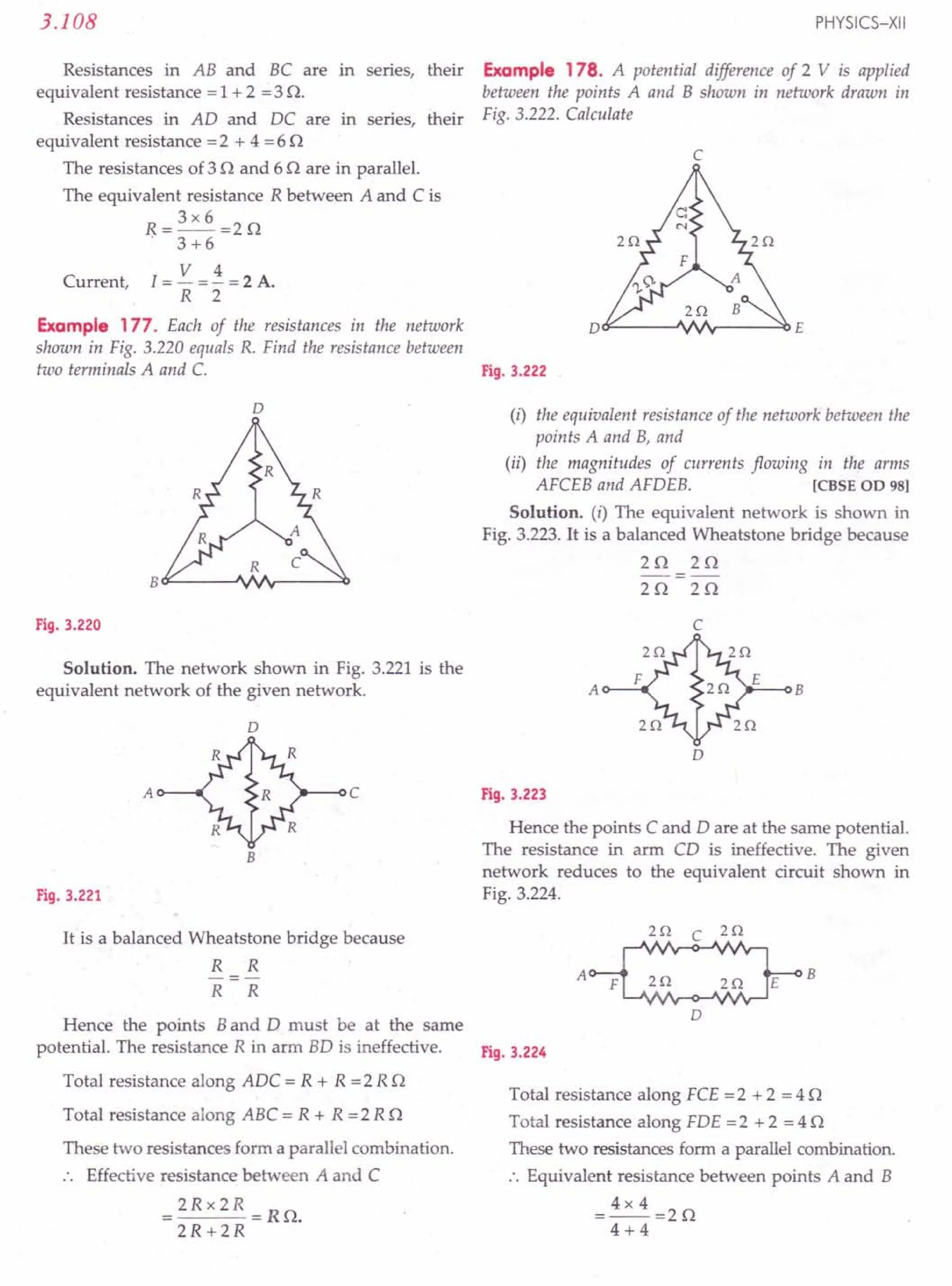
![CURRENT ELECTRICITY
(..) T I . h . . V 2 V 1 A
II ota current In t e CIrCUIt
= - = - =
R z n
Current through arm AFCEB
= Current through arm AFDEB
=..!. A=O.5 A.
2
Example 179. Find the value of the unknown resistance X,
in the following circuit, if no current flows through the
section AO. Also calculate the current drawn by the circuit
from the battery of emf 6 V and negligible internal
resistance. (Fig. 3.225) [CBSEOD 02]
A
A
o
B 1t<---U-...JfV.,.---"" C
6V 2.4Q
6V
Fig. 3.225 Fig. 3.226
Solution. The equivalent circuit for the given
network is shown in Fig. 3.226.
or
As no current flows through the section AO, so the
given circuit is a balanced Wheatstone bridge.
Hence
2 3
4 X
3 x 4
or X=--.=6n
2
The resistance oflO n in section AO is not effective.
Total resistance along BAC = 2 + 4 = 6 n
Total resistance along BOC = 3 + 6 = 9 n
These two resistances form a parallel combi-
nation. The effective resistance between Band Cis
R = 6 x 9 = 18 = 3.6 n.
6 +9 5
Total resistance in the circuit = 3.6 + 2.4 = 6 n.
6V
Current, 1=- = 1 A
6n
Example 180. Six equal resistors, each of value R, are
joined together as shown in Fig. 3.227. Calculate the
equivalent resistance across AB. If a supply of emf e is
connected across AB, compute the current through the arms
DE and AB. [CBSESample Paper 03]
3.109
R
R
R R
C ~J/I.A,--.:::;.D-J'I"~-l E
R R
Bo--L---~F----l
Fig. 3.227
Solution. The equivalent circuits are shown below.
The resistance R in arm DE of the balanced Wheatstone
bridge is ineffective.
o
R R
R R
E
R
R
(a) (b)
A B A B
Fig. 3.228
The equivalent resistance R' across AB is given by
1 1 1 1 4 2
-=-+-+-=-=-
R' 2R 2R R 2R R
R' = R/2
e . e 2e
Current through arm AB = - = -- = - .
R' R/2 R
Current through arm DE = o.
Example 181. Calculate the ratio of the heat produced in
thefour arms of the Wheatstone bridge shown in Fig. 3.229.
. 40n 60n
Solution. As -- = -- B
IOn 15n
The bridge is balanced.
.. p.o. across AB
= P.O. across AD
or o
40 II =60 12
l = 60 =1.5
12 40
II = 1.512
Heats produced in time t in different arms of
Wheatstone bridge are
HAB = I~ Rt =(1.512)2 x 40 x t =90 Ii t
HBC
= I~xlOx t =(1.5I2)2xl0x t =22.5 Ii t
HAD = Ii x 60 x t = 60 Ii t
HDC = Ii x 15x t = 15 Ii t
or
or
Fig. 3.229](https://image.slidesharecdn.com/slaroraclass12thphysicsbyrockytrickster-250318042948-c8b51a5a/75/SL-ARORA-CLASS-12TH-PHYSICS-BY-ROCKY-TRICKSTER-pdf-294-2048.jpg)
![When the resistance in the right gap is increased by
12.50, total resistance becomes 22.5 O. The balance
point shifts towards zero end by 20 cm. Fig. 3.232
3.110
Hence the ratio of the heats produced in the four
arms is
HAB: HBC: HAD: HDC
= 90 Ii t :22.5 Ii t :60 Ii t: 15 Ii t
= 90 :22.5 :60 :15 = 6: 1.5 : 4 : 1.
Example 182. In the following circuit, a metre bridge is
shown in its balanced state. The metre bridge wire has a
resistance of 10 em Calculate the value of the unknown
resistance X and the current drawn from the battery of
negligible internal resistance.
Solution. In balanced condition, no current flows
through the galvanometer.
Here P = Resistance of wire AJ = 40 0
Q = Resistance of wire BJ = 60 0
R =X, 5=60
In the balanced con-
dition,
x
P R A B
---
Q 5 /
40 X
or -=- 6V
60 6
or X=40
Fig. 3.230
Total resistance of wire AB = 1000
Total resistance of resistances X and 6 0 connec-
ted in series = 4 + 6 = 100
This series combination is in parallel with wire AB.
10 x 100 100
Equivalent resistance = = - 0
10 + 100 11
emf of the battery =6 V
.'. Current drawn from the battery,
I= emf =_6_=O.66A.
resistance 100/11
Example 183. With a certain resistance in the left gap of a
slide wire metre bridge, the balance point is obtained when a
resistance of10 0 is taken out from the resistance box. On
increasing the resistancefrom the resistance box by 12.5 0, the
balancepoint shifts by 20 em. Find the unknown resistance.
Solution. With unknown resistance X in the left
gap and known resistance of 100 in the right gap,
suppose the balance point is obtained at 1 em from the
zero end. Then
X 1
-=--
10 100-1
PHYSICS-XII
X 1-20 1-20
22.5 100 - (l - 20) 120 -1
Dividing (1) by (2),
22.5 I 120-1
--=--x---
10 100 -1 I - 20
On solving, we get 12-1201 + 3600 =0
I =60 em
...(2)
From (1),
X
10
60 60 x 10
or X=---=150.
40
100 -60
Example 184.In metre bridge, the null point isfound at a
distance of 60.0 em from A. If now a resistance of 50 is
connected in series with 5, the null point occurs at 50 em.
Determine the values of Rand 5. [Fig. 3.231]. [CBSE D 10]
A·~~------+- -r~B
Fig. 3.231
jlj'l'i1j'j,j,jij,j'jijijiiijljijljIPi'lIlijijijijljijijij'I'il
R 60 3
Solution. In first case, - = - = - ...(i)
5 40 2
R 50
In second case, -- = - ...(ii)
5+5 50
On di 'din ("b (..) 5+5_3
IV! g IJ Y us, -5- - 2
or 25+10=35
m 5=WO
and R = ~ 5 = ~ x 10 = 15 0
2 2
Example 185. In a metre bridge, the null point isfound at
a distance of 40 cm from A. If a resistance of 12 0 is
connected in parallel with 5, the null point occurs at 50.0 em
from A. Determine the values of Rand 5. [Fig. 3.232]
[CBSE D 10]
1Hl
.JIV'y,
I
I
...(1)
A~~ 4- ~~B
jiiii"""""'!"""!"""j'I'I'I'j""""""'!'jilliljiil](https://image.slidesharecdn.com/slaroraclass12thphysicsbyrockytrickster-250318042948-c8b51a5a/75/SL-ARORA-CLASS-12TH-PHYSICS-BY-ROCKY-TRICKSTER-pdf-295-2048.jpg)
![CURRENT ELECTRICITY
Solution.
In first case,
R 40 2
-----
5 60 3
R 50
lIS-50
5+12
In second case,
R 12 2
5=6n
or -=--=- or
5 5+12 3
and
2 2
R=-x5=-x6=4n
3 3
Example 186. A resistance R =2 n is connected to one of
the gaps in a metre bridge, which uses a wire of length 1m.
An unknown resistance X > 2 n is connected in the other gap
as shown in thefigure. The balancepoint is noticed at '1'from
the positive end of the battery. On interchanging R and X, it
isfound that the balance point further shifts by 20 em (away
from end A). Neglecting the end correction, calculate the
value of unknown resistance X used. [CBSE OD OS]
X
A~~~~~----------~B
-- (100 - /) em
Fig. 3.233
Solution. In first case,
R I
- --
X 100-1
In second case,
X
R
1+20 1+20
80 -I
100 -(I + 20)
or
On multiplying the two equations,
l=_I_x 1+20
100-180-/
8000 -1801 + 12= 12+ 201
2001 =8000
1= 40 em
Now X = I + 20 R = 40 + 20 x 2 = 3 n.
80-1 80-40
or
or
3.111
null point isfound to shift by 10 em towards the end A of the
wire. Find the position of null point if a resistance of30 n
were connected in parallel with Y. [CBSE Sample Paper 08]
X Y
AU-------~----------~ c
111--1 ---~(.
Fig. 3.234
Solution. In first case,
X 60
Y 40
X 3
or
Y 2
In second case,
_X_=50=1
Y + 15 50
X x Y + 15 = ~x 1
Y X 2
1+ 15 = ~
Y 2
Y=30n
X=~Y=~x30=45n
2 2
When a resistance of 30 n is connected in parallel
with Y, the resistance in the right gap becomes
Y' = 30Y = 30 x 30 = 15 n
30+Y 30+30
or
or
Suppose the null point occurs at I em from end A
Then
X
15
I
100 -I
or
45 I
-=--
15 100-1
or 300-31=1
or 41 = 300 or 1=75 em.
Example 188. When two known resistances, Rand 5, are
connected in the left and right gaps of a metre bridge, the
balance point isfound at a distance 11
from the 'zero end' of
x·
..JN'v,
,
,
Example 187. The given figure shows the experimental
setup of a metre bridge. The null point isfound to be 60 em
away from the end A with X and Y in position as shown.
When a resistance of 15 n is connected in series with Y, the Fig. 3.235
A B
IIj'jll'P,·I'lIl'lIl'lIiilijilijijljljljiltjljiiii'r'illliiiilj](https://image.slidesharecdn.com/slaroraclass12thphysicsbyrockytrickster-250318042948-c8b51a5a/75/SL-ARORA-CLASS-12TH-PHYSICS-BY-ROCKY-TRICKSTER-pdf-296-2048.jpg)
![3.112
the metre bridge wire. An unknown resistance X is now
connected in parallel to the resistance 5 and the balance point
is now found at a distance 12from the zero end of the metre
bridge wire. Obtain aformula for X in terms of 11,12and S.
[CBSE 0 04C, IOC ; 00 09]
Solution. In first case,
R
5
...(i)
In second case,
R 12
XS/(X+S) 100-12
Dividing (ii) by (i), we get
X + 5 = ~ ( 100 -11 J or
X 11 100 -12
X= 5
~ ( 100 -11 J-1
11 100 -12
problems ForPractice
1. Four resistances of 15Q, 12Q, 4 Q and 10Q respec-
tively are connected in cyclic order to form a
Wheatstone bridge. Is the network balanced ? If
not, calculate the resistance to be connected in
parallel with the resistance of 10Q to balance the
network. (Ans. Bridge is not balanced, 10Q)
B
PHYSICS-XII
4. Calculate the equivalent resistance between points
A and B of the network shown in Fig. 3.238.
[CBSE 0 99] (Ans. 2Q)
(
..) Fig.3.238
...II
2. The Wheatstone's bridge
of Fig. 3.236 is showing
no deflection in the
galvanometer joined
between the points B
and D. Compute the
value of R.
D
(Ans.25Q)
Fig. 3.236
3. (i) Calculate the equivalent resistance of the given
electrical network between points A and B.
(ii) Also calculate the current through CD and ACB,
if a 10 V d.c. source is connected between A and B,
and the value of R
is assumed as 2 Q.
[CBSE 00 08]
[Ans. (i) RAB = RQ
(ii) lCD = 0,
lACB = 2.5 A]
c
Dt:F------J'INr-----O()E
Fig. 3.237
5. Calculate the equivalent resistance between the
points A and B of the network shown in Fig.3.239.
(Ans. R)
Fig. 3.239
6. Calculate the resistance between the points A and B
of the network shown in Fig. 3.240. (Ans. 8Q)
Ion IOn
40n
Fig. 3.240
7. For the network shown in Fig. 3.241,determine the
value of R and the current through it, if the current
through the branch AO is zero. (Ans. 6Q, 0.5 A)
A
iz n
an
A D B
B O'---oi I-~"".Ir--.::o C
lOV 2n
Fig. 3.241 Fig. 3.242
8. The potentiometer wire AB shown in Fig. 3.242 is
40 ern long. Where should the free end of the
galvanometer be connected on AB so that the
galvanometer may show zero deflection ?
(Ans. 16 em from A)](https://image.slidesharecdn.com/slaroraclass12thphysicsbyrockytrickster-250318042948-c8b51a5a/75/SL-ARORA-CLASS-12TH-PHYSICS-BY-ROCKY-TRICKSTER-pdf-297-2048.jpg)
![CURRENT ELECTRICITY
9. The potentiometer wire AB shown in Fig. 3.243 is
50 cm long. When AD = 30em, no deflection occurs
in the galvanometer. Find R. (Ans. 40)
x 15.
6Q R
B
J
100 em
A 0 B 5V 16.
Fig. 3.243 Fig. 3.244
10. Calculate the value of unknown resistance X and
the current drawn by the circuit, assuming that no
current flows through the galvanometer. Assume
the resistance per unit length of the wire AB to be
0.010/ cm. (Fig. 3.244) [CBSE D 01]
(Ans. 60, 5.5 A)
11. In Fig 3.245, P = 30, Q = 20, R = 60, S =40 and
X = 5 n Calculate the current l. [CBSE D 921
(Ans. 0.6 A)
c
I
r r
r
r r
o
6V
2.0 V
Fig. 3.245 Fig. 3.246
12. Each resistor r shown in Fig. 3.246 has a resistance
of 100 and the battery has an emf of 6 V. Find the
current supplied by battery. (Ans. 0.6 A)
13. Find the equivalent resistance between the points X
and Y of the network shown in Fig. 3.247.
(Ans.100)
F'19·3.247
3.113
14. In a metre bridge, the length of the wire is 100 em.
At what position will the balance point be obtained
if the two resistances are in the ratio 2 : 3 ?
(Ans. 40 em)
In the metre bridge experimental set up, shown in
Fig. 3.248, the null point' D' is obtained at a distance
of 40 cm from end A of the metre bridge wire. If a
resistance of 100 is connected in series with X, null
point is obtained at AD = 60 cm. Calculate the
values of X and Y. [CBSE D 13]
(Ans. 80,120)
In a metre-bridge experiment, two resistances P
and Q are connected in series in the left gap. When
the resistance in the right gap is 500, the balance
point is at the centre of the slide wire. If P and Q are
connected in parallel in the left gap, the resistance
in the right gap has to be changed to 120 so as to
obtain the balance point at the same position. Find
P and Q. (Ans. P= 300, Q = 200)
17. In a metre bridge when the resistance in the left gap
is 20 and an unknown resistance in the right gap,
the balance point is obtained at 40 cm from the zero
end. On shunting the unknown resistance with 20,
find the shift of the balance point on the bridge
wire. (Ans. 225 em)
18. Fig. 3.248 shows experimental set up of a metre
bridge. When the two unknown resistances X and Y
are inserted, the null point Dis obtained 40 cm from
the end A. When a resistance of 100 is connected in
series with X, the null point shifts by 10 cm. 'Find
the position of the null point when the 100
resistance is instead connected in series with
resistance 'Y'. Determine the values of the resis-
tances X and Y. [CBSE D 09]
X Y (Ans. X = 200,
Y=300,
I' = 33.3 em]
o c
Fig. 3.248
HINTS
1. The four resistances' are
connected in a cyclic order
, i I ! t ,i j
as shown in Fig. 3.2491 i
,
15 10
~*-
12 4
I" Thp~ ':Yh~atstQne~ridge i.~; I'
not. balanced. To: balance
the network, suppose
B
As
c
'0
Fig. 3.249](https://image.slidesharecdn.com/slaroraclass12thphysicsbyrockytrickster-250318042948-c8b51a5a/75/SL-ARORA-CLASS-12TH-PHYSICS-BY-ROCKY-TRICKSTER-pdf-298-2048.jpg)
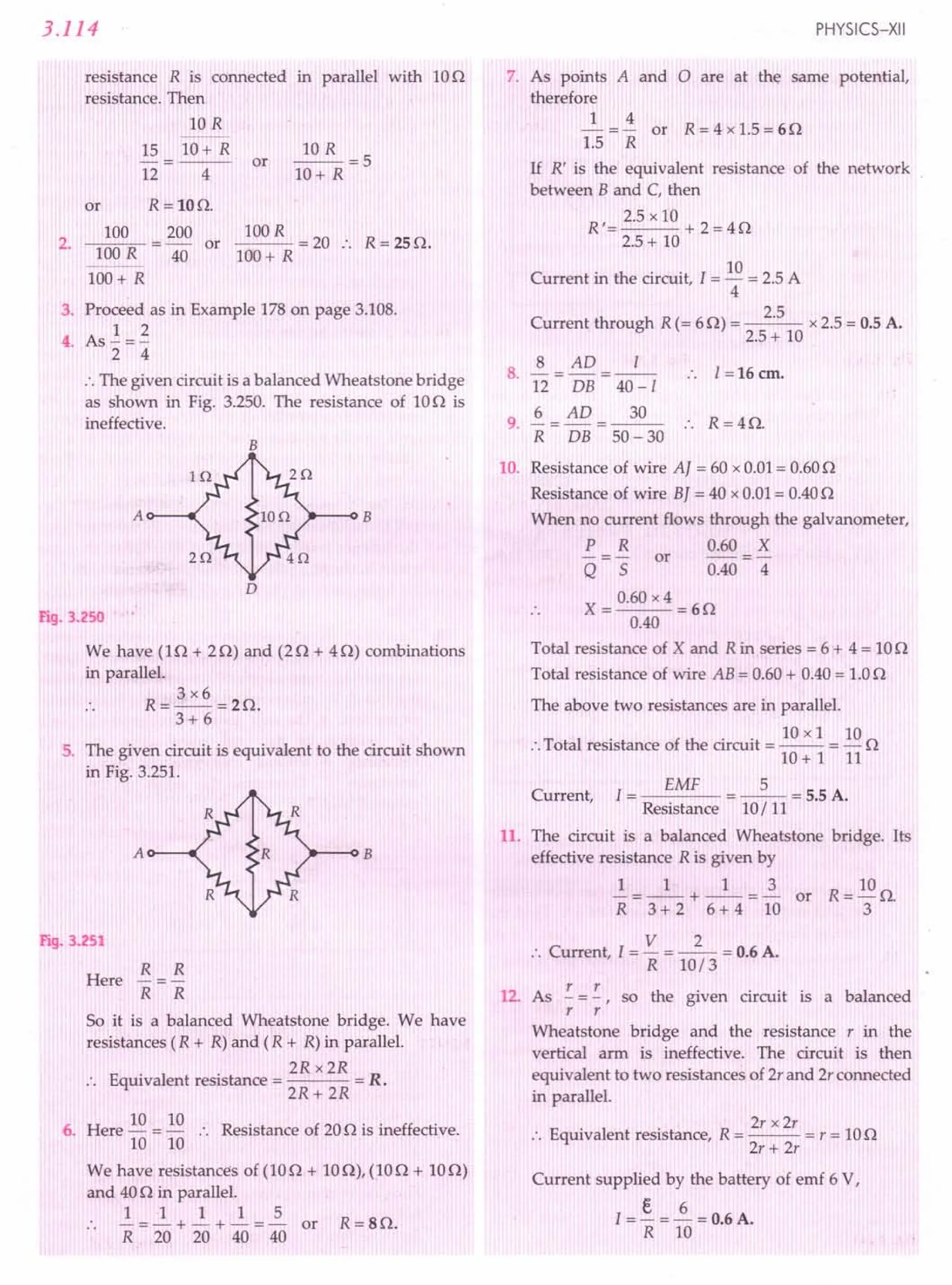
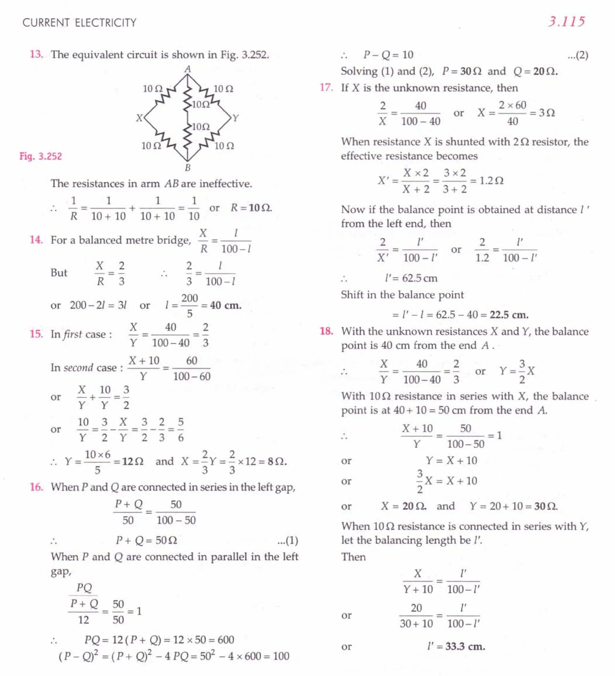
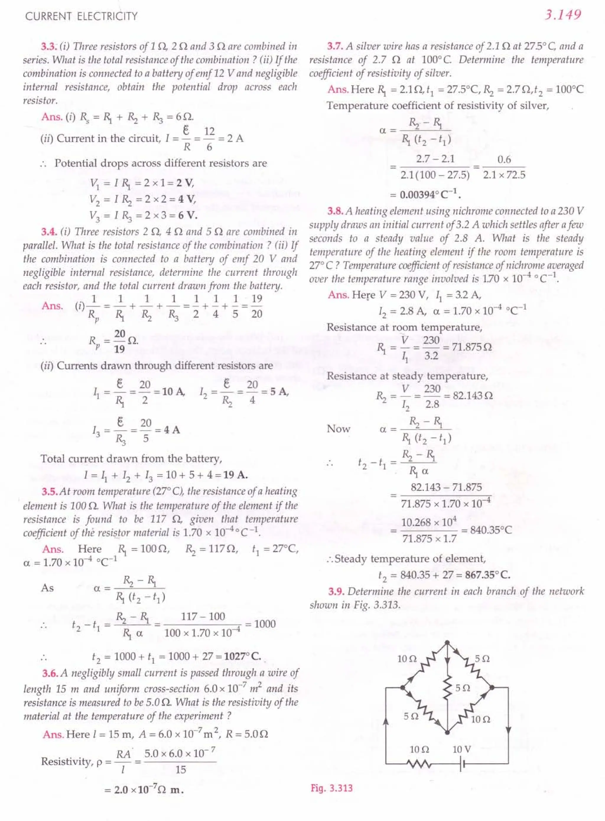
![3.150
Ans. Let I, II' 12
, 13 be the currents as shown in
Fig. 3.314. We apply Kirchhoff's second rule to different
loops.
B
LIon
Fig. 3.314
For loop ABDA,
lOll + 513 - 512 = 0
For loop BCDB,
5(11 -13) -10(12 + 13) - 513 = 0
For loop ADCFGA,
512 + 10(12 + 13) + 10(11 + 12) = 10 (":
1011 - 512 + 513 = 0
511 - 1012 - 2013 = 0
1011 + 2512 + 1013 = 10
Solving equations (1), (2) and (3), we get
4 6 2
11= 17 A, 12 = 17 A, 13 = - 17 A
or
11+ 12 = I)
...(1)
...(2)
...(3)
Currents in different branches are
4 6
lAB = 11=17A, IBC=11-13=17A,
4
IDC = 12 + 13 = - A
17
6 2
IAD = 12 = - A, IBD = 13 = - - A
17 17
Total Current,
10
I = II + 12 = - A.
17
3.10. (i) In a metre bridge (Fig. 3.315), the balance point is
found to be at 39.5 em from the end A, when the resistor Y is of
12.5 n.Determine the resistance of X. Why are the connections
between resistors in a Wheatstone or metre bridge made of thick
copper strips ? (jj) Determine the balance point of the bridge
x y
A~--~~~----------~C
Fig. 3.315
PHYSICS-XII
above if X and Yare interchanged. (iii) What happens if the
galvanometer and cell are interchanged at the balance point of
the bridge? Would the galvanometer show any current?
[CBSE D 05]
Ans. Here I = 35.9 ern, R = X = 7, 5 = Y = 12.5 n
As 5
- 100 - I R . 2 _ 100 - 39.5 R
- -- x .. 1 .5- x
I 39.5
R = 12.5 x 39.5 = 8.16 n
60.5
or
Connections are made by thick copper strips to
minimise the resistances of connections which are not
accounted for in the above formula.
or
(ii) When X and Yare interchanged,
R = Y = 12.5n, 5= X = 8.16n, I =?
100 -I 100-1
5= -1- x R :. 8.16=-1- x 12.5
8.161 = 1250 - 12.51
1250
1= -- = 60.5 n , from the end A.
20.66
As
or
(iii) When the galvanometer and cell are interchanged
at the balance point, the conditions of the balanced bridge
are still satisfied and so again the galvanometer will not
show any current.
3.11. A storage battery of emf B.OVand internal resistance
0.5 n is being charged by a 120 V de supply using a series
resistor of 15.5 n. What is the terminal voltage of the battery
during charging ? What is the purpose of having a series
resistor in the charging circuit ?
Ans. When the storage battery of 8.0 volt is charged
with a de supply of 120 V, the net emf in the circuit will be
E.' = 120 - 8.0 = 112 V
Current in the circuit during charging
1=~= 112 =7 A
R + r 15.5 + 0.5
The terminal voltage of the battery during charging,
V = E.+ lr = 8.0 + 7 x 0.5 = 11.5 V
The series resistor limits the current drawn from the
external source. In its absence, the current will be dange-
rously high.
3.12. In a potentiometer arrangement, a cell of emf 1.25 V
gives a balance point at 35.0 em length of the wire. If the cell is
replaced by another cell and the balance point shifts to 63.0 em,
what is the emf of the second cell ?
Ans. Here E.1= 1.25 V, 4 = 35.0 em, 12= 63.0 em,
E.2 =?
As
E.2 12
E.1 = 1;
e 12 e 63 x 1.25
C,2= - x C,1= = 2.25 V.
4 35](https://image.slidesharecdn.com/slaroraclass12thphysicsbyrockytrickster-250318042948-c8b51a5a/75/SL-ARORA-CLASS-12TH-PHYSICS-BY-ROCKY-TRICKSTER-pdf-303-2048.jpg)
![CURRENT ELECTRICITY
3.13. The number density of free electrons in a copper
conductor is 85 x 1028
m" 3. How long does an electron take to
drift from one end of a wire 3.0 m long to its other end? The area
of cross-section of the wire is 2.0 x 10- 6 m2
and it is carrying a
current of 3.0 A.
Ans. Here n =8.5 x 1028
m-3, 1=3 m,
A =2.0 x 10⁻⁶ m2, e =1.6 x 10⁻¹⁹ C, I =3.0 A
Drift speed,
I
v -
d - enA
3 -1
= ms
1.6 x 10-19 x 8.5 x 1028 x 2 x 10-6
3 ms-1 = 1.1 x 10⁻⁴ ms-1
16 x 85 x 2 x 10
Required time,
I 3 4
t = - = 4 S = 2.73 x 10 s = 7.57 h.
vd 1.1 x 10-
3.14. The earth's surface has a negative surface charge
density of10-9
Cm-2
. The potential difference of400 kV between
the top of the atmosphere and the surface results (due to the low
conductivity of the lower atmosphere) in a current of only
1800 A over the entire globe. If there were no mechanism of
sustaining atmospheric electric field, how much time (roughly)
would be required to neutralise the earth's surface? (Radius of
the earth = 6.37 x 10⁶
m ).
An . Surface charge density,
c = 10-9Cm-2
Radius of the earth,
R = 6.37 x 10⁶
m
Current, I = 1800 A
Total charge of the globe,
q = surface area x c = 41t R2
cr
= 4 x 3.14 x (6.37 x 106)2 x 10-9
= 509.65 x 10³
C
Required time,
q 509.65 x 10³
t = - = = 283.13 s = 283 s.
I 1800
3.15. (a) Six lead-acid type of secondary cells each of emf2.0 V
and internal resistance 0.0150 are joined in series to provide a
supply toa resistance of 8.5O. What are the current drawn from
the supply and its terminal voltage ?
(b) A secondary cell after long use has an emf of 1.9 V and a
large internal resistance of 380 0 . What maximum current can
be drawn from the cell? Could the cell drive the starting motor
of a car?
Ans. (a) Here € = 2 V, r = 0.0150, R = 8.50, n= 6
When the cells are joined in series, the current is
I=~= 6x2 =~A=1.4A
R + nr 8.5 + 6 x 0.015 8.59
3.151
Terminal voltage,
V = IR = 1.4 x 8.5 = 11.9 V.
(b) Here € = 1.9 V, r = 3800
I = §. = ~ A = 0.005 A
max r 380
This secondary cell cannot drive the starting motor of
a car because that' requires a large current of about 100 A
for a few seconds.
3.16. Two wires of equal length, one of aluminium and the
other of copper have the same resistance. Which of the two wires
is lighter ? Hence explain why aluminium wires are preferred
for overhead power cables.
Given PAl = 2.63 x 1O-8
0m, PCu = 1.72 x10⁻⁸
Om,
relative density of Al = 2.7and that of Cu = 8.9.
Ans. Mass = volume xdensity = Al d
= Pi.Id = pd 12
R R
I
[.,'R=P-]
A
As the two wires are of equal length and have the
same resistance, their mass ratio will be
ncu PCu dcu 1.72 x 10-8 x 8.9
-=---= 8 =2.1558=2.2
mAl PAl dAl 2.63 x10 x2.7
i.e., copper wire is 2.2 times heavier than aluminium wire.
Since aluminium is lighter, it is preferred for long sus-
pension of cables otherwise heavy cable may sag down
due to its own weight.
3.17. What conclusion can you draw from the following
observations on a resistor made of alloy manganin :
Current Voltage Current Voltage
I(A) V I(A) V
0.2 3.94 3.0 59.2
0.4 7.87 4.0 78.8
0.6 11.8 5.0 98.6
0.8 15.7 6.0 118.5
1.0 19.7 7.0 138.5
2.0 39.4 8.0 158.0
Ans. We plot a graph between current I (along y-axis)
and voltage V (along x-axis) as shown in Fig. 3.316.
10 20 30 40 50 60 70 80 90 100110120130140150160170
V~
Fig. 3.316 V-I graph for rnanganin.](https://image.slidesharecdn.com/slaroraclass12thphysicsbyrockytrickster-250318042948-c8b51a5a/75/SL-ARORA-CLASS-12TH-PHYSICS-BY-ROCKY-TRICKSTER-pdf-304-2048.jpg)
![3.152
Since the V-I graph is almost a straight line, therefore,
manganin resistor is an ohmic resistor for given ranges of
votlage and current. As the current increases from 0 to 8 A,
the temperature increases but the resistance of manganin
does not change. This indicates that the temperature
coefficient of resistivity of manganin alloy is negligibly
small.
3.18. Answer the following questions:
(a) A steady current flows in a metallic conductor of
non-uniform cross-section.Say which of thesequantities
is constant along the conductor: current, current
density, electric field, drift speed? [CBSE DISC]
(b) Is Ohm's law universally applicablefor all conducting
elements ? If not, give examples of elements which
do not obey Ohm's law.
(c) A low voltage supply from which one needs high
current must have very low internal resistance.
Why?
(d) Why a high tension (H. TJ supply of say 6 kV must
have a very large internal resistance?
Ans. (a) Only current is constant because it is given to
be steady. Other quantities: current density, electric field
and drift speed vary inversely with area of cross-section.
(b) No, Ohm's law is not universally applicable for all
conducting elements. Examples of non-ohmic elements
are vacuum diode, semiconductor diode, thyristor, gas
discharge tube, electrolytic solution, etc.
(c) The maximum current that can be drawn from a
voltage supply is given by
e
Imax
=-
r
Clearly, Imax
will be large if r is small.
(d) If the internal resistance is not very large, then the
current will exceed the safety limits in case the circuit is
short-circuited accidentally.
3.19. Choose the correct alternative:
(a) Alloys of metals usually have (greater! lesser)
resistivity than that of their constituent metals.
(b) Alloys usually have much (lower/higher) temperature
coefficients of resistance than pure metals.
(c) The resistivity of the alloy manganin is nearly
independent of/increases rapidly with increase of
temperature.
(d) The resistivity of a typical insulator te.g., amber) is
greater than that of a metal by afactor of the order of
(1022
/103
).
Ans. (a) greater (b) lower (c) is nearly independent of
(d) 1022
.
3.20. (a) Given n resistors each of resistance R, how will you
combine them to get the ti) maximum, (ii) minimum effective
resistance ? What is the ratio of the maximum to minimum
resistance ?
PHYSICS-XII
(b) Given the resistance of Elf 2Of 30, how will you
combine them to get an equivalent resistance of:
(i) 110 (ii) 110 (iii) 60 (iv) i.. 0 ?
3 5 11
[CBSE F 15]
(c) Determine the equivalent resistance of the following .
networks:
(a)
R
(b)
Fig. 3.317
Ans. (a) For maximum effective resistance, all the n
resistors must be connected in series.
:. Maximum effective resistance,
Rs = nR
For minimum effective resistance, all the n resistors
must be connected in parallel. It is given by
1 1 1 1 n
- = - + - + - + n terms =-
Rp R R R R
:. Minimum effective resistance,
R =~
p n
Ratio of the maximum to minimum resistance is
~ = nR = ~ =n2: 1.
Rp R/ n 1
(b) Here R,.= 10, ~ =20, R:,= 30
(i) When parallel combination of 10 and 2 0 resistors
is connected in series with 30 resistor [Fig.3.318(a)], the
equivalent resistance is
R=R +R:,= R,.~ +R:,
P R,.+~
1x2 2 11
=--+3=-+3=-0.
1+ 2 3 3
(ii) When parallel combination of 20 and 30 resistors
is connected in series with 1 0 resistor [Fig.3.318(b)], the
equivalent resistance is
~R:, 2x3 6 11
R= +R,.=--+1=-+1=-0.
~+R:, 2+3 5 5](https://image.slidesharecdn.com/slaroraclass12thphysicsbyrockytrickster-250318042948-c8b51a5a/75/SL-ARORA-CLASS-12TH-PHYSICS-BY-ROCKY-TRICKSTER-pdf-305-2048.jpg)
![(iii) When the three resistances are connected in series
[Fig. 3.318(c)], the equivalent resistance is
R = ~ + ~ + R:J = (1 + 2 + 3) 0 = 6 o.
(iv) When all the resistances are connected in parallel
[Fig. 3.318(d)],
111111111
R = ~ + ~ + R:J = 1 + "2+ "3= 6 Fig. 3.321
CURRENT ELECTRICITY
lQ
~3AQA_
~vvv--
(a)
2Q
~AQA_
~vvv--
(b)
lQ
3Q
2Q
(c) (d)
Fig. 3.318
Equivalent resistance, R = ~ n.
11
(c) The network shown in Fig. 3.317(a) is a series
combination of four identical units. One such unit is
shown in Fig. 3.319(a) and it is equivalent to a parallel
combination of two resistances of 20 and 40 as shown in
Fig.3.319(b).
(a) (b)
Fig. 3.319
Resistance R of one such unit is given by
1 1 1 2+1 3
-=-+-=--=-
R 2 4 4 4
R=io
3
.. Resistance of the total network (4 such units)
= 4 xi = 16 o.
3 3
(ii) The network shown in Fig. 3.319(b) is a series
combination of 5 resistors, each of resistance R.
:. Equivalent resistance = 5 R.
3.21. Determine the current drawn from a 12 V supply with
internal resistance 0.50 by thefollowing infinite network. Each
resistor has 10 resistance.
or
3.153
lQ 10 10 10 10 A
10
10 B
Fig. 3.320
Ans. Let the equivalent resistance of the infinite
network be X. This network consists of infinite units of
three resistors of 1 0, 1 0, 1 O. The addition of one more
such unit across AB will not affect the total resistance. The
network obtained by adding one more unit would appear
as shown in Fig. 3.321.
x
10
10
B
Resistance between A and B
= Resistance equivalent to parallel
combination of X and 10
X xl X
--=--
x i t X+1
Resistance between P and Q
X X
=1+--+1=2+--
X+1 x r i
or
This must be equal to the original resistance X.
X
X=2+--
1+ X
X2 - 2X - 2 = 0
X=l±.J3
or
As the value of resistance cannot be negative, so
X = 1 + .J3 = 2.7320
Current, I = emf
Total resistance
E. 12
X + r 2.732 + 0.5
= 3.713 A
3.22. Figure 3.322 shows a potentiometer with a cell of
2.0 V and internal resistance 0.40 0 maintaining a potential
drop across the resistor wire AB. A standard cell which
maintains a constant emf of 1.02 V (jor very moderate currents
upto afew A) gives a balance point at 67.3 cm length of the wire.
To ensure very low currents drawn from the standard cell, a
very high resistance of 600 k 0 is put in series with it, which is
shorted close to the balance point. The standard ceil is then
replaced by a cell of unknown emf E. and the balallce point found
similarly turns out to be at 82.3 em length of the wire.
(a) What is the value ofE. ?](https://image.slidesharecdn.com/slaroraclass12thphysicsbyrockytrickster-250318042948-c8b51a5a/75/SL-ARORA-CLASS-12TH-PHYSICS-BY-ROCKY-TRICKSTER-pdf-306-2048.jpg)
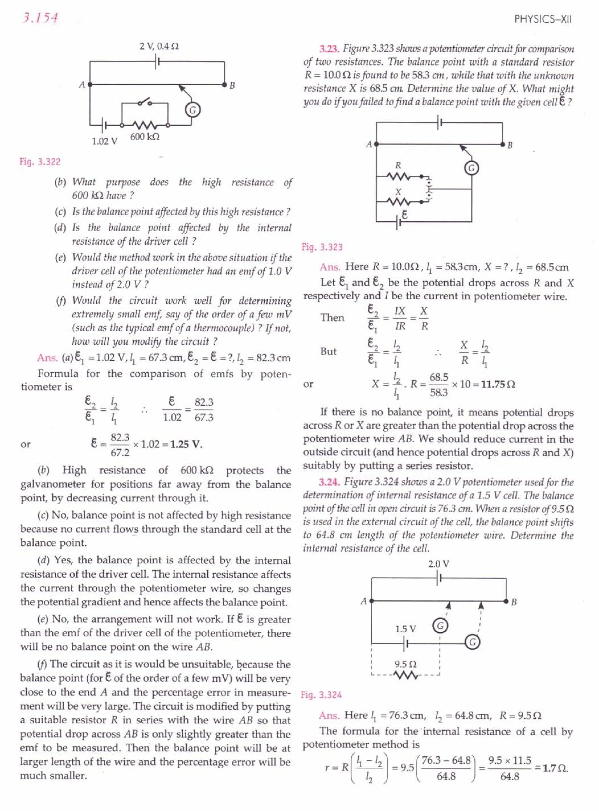
![CURRENT ELECTRICITY 3.155
Text Based Exercises
"YPE A : VERY SHORT ANSWER QUESTIONS (1 mark each)
1. Define electric current. What is the 51unit of electric
current?
2. Write the relation between a coulomb and an
ampere. [ISCE 96]
3. What does the direction of electric current signify in
an electric circuit?
4. What is electromotive force? State its 51Unit.
[Punjab 2000]
5. State the condition in which terminal voltage across
a secondary cell is equal to its emf?
[CBSE D 2000]
6. Define an emf of one volt.
7. State Ohm's law. [ISCE 95]
8. Name the colours corresponding to the digits 4 and
7 in the colour code scheme for carbon resistors.
[CBSE SP 15]
9. Define resistance and state its 51unit. [CBSE D 92C]
10. Define Ohm.
11. Define conductance of a material. Give its 51unit.
[CBSE D 02]
12. Define electrical conductivity of a material. Give its
51unit. [CBSE D 03,14]
13. How much is the resistance of an air-gap?
14. How much is the resistance of a closed plug-key?
15. Which metal has the lowest resistivity ?
16. Define resistivity of a material. State its 51unit.
[ISCE 93]
17. What is the order of resistivity of an insulator?
[Punjab 97C]
18. What is the ratio of the resistivity of a typical
insulator to that of a metal?
19. What is the average velocity of free electrons in a
metal at room temperature?
20. Give the order of magnitude of the number density
of free electrons in a metal.
21. Give the order of magnitude of thermal velocity
and drift velocity of free electrons in a conductor
carrying current at room temperature.
22. What is the order of resistivity of conductor?
23. Define temperature coefficient of resistivity.
24. How does the random motion of free electrons in a
conductor get affected when a potential difference
is applied across its ends? [CBSE D 14C]
25. Define the term' drift velocity' of charge carriers in
a conductor and write its relationship with the
current flowing through it. [CBSE D 14]
26. Write the expression for the drift velocity of charge
carriers in a conductor of length 'I' across which a
potential difference 'V' is applied. [CBSE OD14C]
27. How does one explain increase in resistivity of a
metal with increase of temperature? [CBSE OD14C]
28. Define the term mobility of charge carriers in a
conductor. Write its 51unit. [CBSE D 14; OD15]
29. Plot a graph showing variation of resistivity of a
conductor (copper) with temperature.
[CBSE D 14; F 15]
30. Plot a graph showing variation of current versus
voltage for the material GaAs. [CBSE D 14]
31. Sketch a graph showing variation of resistivity of
carbon with temperature. [CBSE D 06]
Or
Show on a graph, the variation of resistivity with
temperature for a typical semiconductor Si.
[CBSE DOS, 12,14]
32. Name two materials whose resistivity decreases
with the rise of temperature.
33. How does the conductance of a semi-conducting
material change with rise in temperature?
34. Of copper and nichrome, which one has possibly
larger value of temperature coefficient of
resistance? [CBSE D 95C]
35. How does resistivity of alloy manganin change
with temperature?
. 36. Bow does the resistance"of an insulator change
with temperature? I
37. Name two parameters which determine the
resistivity of a material.
38. How is the conductivity of an electrolyte affec-
ted by the increase of temperature? [CBSE D 95]
39. If potential difference V applied across a conductor
is increased to 2 V, how will the drift velocity of the
electrons change? [CBSE OD2000C]
40. What is a non-ohmic device? State one example.
[Punjab 02]
41. What is a linear resistor?
42. Give an example of non-ohmic device which shows
up negative resistance.](https://image.slidesharecdn.com/slaroraclass12thphysicsbyrockytrickster-250318042948-c8b51a5a/75/SL-ARORA-CLASS-12TH-PHYSICS-BY-ROCKY-TRICKSTER-pdf-308-2048.jpg)
![3.156
43. A cell of emf 'e' and internal resistance 't' draws a
current '1'. Write the relation between terminal
voltage 'V' in terms of e, I and r. [CBSE aD 13]
44. Two identical cells, each of emf e,having negligible
internal resistance r, are connected in parallel with
each other across an external resistance R. What is
the current through this resistance? [CBSE aD 13]
45. A 4 n non-insulated resistance wire is bent 1800
in
the middle and the two halves are twisted together.
What will be its new resistance? [CBSE D 10C]
46. Can Kirchhoff's laws be applied to both d.c. and a.c.
circuits?
47. On what conservation principle is the Kirchoff's
first law based ?
48. On what conservation principle is the Kirchhoff's
second law based ?
49. Name the device used for measuring the emf of a
cell. [CBSE D 96]
50. Name the device used for measuring the internal
resistance of a secondary cell. [CBSE D 96]
51. Define potential gradient. Give its 51 unit.
52. Name the principle on which a metre bridge works.
53. What is a Wheatstone bridge? [CBSE D 03]
54. The given graph shows the variation of resistance
of mercury in the temperature' range 0 < T < 4 K
Name the phenomenon shown by the graph.
[CBSEOD 03]
c
~ 0.16
u
§
'0 0.08
~
OL-~--~L-~--~~
246
Temperature (K)
Fig. 3.325
55. If the resistances in the three successive arms of a
balanced Wheatstone bridge are 1, 2 and 36n
respectively, what will be the resistance of the
galvanometer placed in the fourth arm ?
56. Current I flows through a potential drop V across a
conductor. What is the rate of production of heat?
•[CBSE D 93C]
57. The rate of production of heat is given by P = VI.
Is this relation valid for a non-ohmic conductor?
58. How is electric energy related to electric power?
59. Ofwhich physicalquantity is theunit kilowatt hour?
60. What do you mean by 1unit of electric energy in
domestic-use ?
61. How many joulesofenergyareequivalentto 1kWh?
PHYSICS-XII
62. How many kilowatt hours (kWh) are there in one
joule? [CBSE on 99C]
63. The applied p.d. across a given resistance is altered
so that heat produced per second increases by a
factor of 9. By what factor does the applied p.d..
change? [CBSE on 99C]
64. Two electric bulbs are rated at 220V - 100W and
220V - 60W. Which one of these has greater
resistance and why? [CBSE Sample Paper 03]
65. The maximum power dissipated in a 10,000n
resistor is 1W. What is the maximum current?
[ISCE 93]
66. What is the safest voltage you can safely put across
a 98n. 0.5W resistor? [ISCE 97]
67. How much charge flows through a 250 V, 1,000W
heater in one minute? [ISCE 96]
68. A heating element is marked 210V, 630W. What is
the value of the current drawn by the element when
connected to a 210V de source? [CBSE D 13]
69. A heating element is marked 210V, 630W. Find the
resistance of the element when connected to a 210V
dc source. [CBSE D 13]
70. Two resistors of 2 nand 4 n are connected in
parallel to a constant d.c. voltage. In which case
more heat is produced? [CBSE D 98C ]
71. Two bulbs whose resistances are in the ratio 1 :2 are
connected in parallel to a source of constant
voltage. What will be the ratio of power dissipation
in these bulbs? [CBSE D 2000C]
72. Distinguish between kilowatt and kilowatt hour.
73. Which has a greater resistance-kW electric heater
or a 100W filament bulb both marked for 220V ?
[CBSE D OlC]
74. The coil of a heater is cut into two equal halves and
only one of them is used into heater. What is the
ratio of the heat produced by this half coil to that by
original coil ?
75. What do you mean by the maximum power rating
of a resistor?
76. Express power transferred per unit volume into
joule heat in a resistor in terms of current density.
77. Write two special characteristics of the wire of an
electric heater. [CBSE D 94]
78. What are the characteristics of a fuse wire?
79. What is the difference between a heater wire and a
fuse wire?
80. Two identical heaters rated 220V, 1000Ware
placed in series with each other across a 220V line.
What is their combined power?
81. Write an expression for the resistivity of a metallic
conductor showing its variation over a limited
range of temperature. [CBSE D 08C]](https://image.slidesharecdn.com/slaroraclass12thphysicsbyrockytrickster-250318042948-c8b51a5a/75/SL-ARORA-CLASS-12TH-PHYSICS-BY-ROCKY-TRICKSTER-pdf-309-2048.jpg)
![CURRENT ELECTRICITY
82. v
83.
The plot of the
variation of potential
difference across a
combination of three
identical cells iri series,
versus current is as
shown in Fig. 3.326.
What is the emf of each
cell ? [CBSE
0 08]
A (i) series (ii) parallel combination of two given
resistors is connected one-by-one, across a cell. In
which case will the terminal potential difference,
across the cell, have a higher value?
[CBSE
00 08C]
6V
o 1A
Fig. 3.326
84. The I-V charac-
teristics of a resistor
are observed to
deviate from a
straight line for higher
values of current as
shown in Fig. 3.327.
Why?
V~
Fig. 3.327
85.
[CBSE
SP08]
Two identical slabs of given metal are joined
together, in two different ways, as shown in
Figs. 3.328(i) and (ii). What is the ratio of the
resistances of these two combinations?
[CBSE
0 10C]
(i) (ii)
Fig. 3.328
Answers
3.157
86. A resistance R is connected across a cell, of emf e
and internal resistance r. A potentiometer now
measures the p.d., between the terminals of the cell,
as V. State the expression for 'r' in terms ofe, V and
R [CBSE
011]
87.: A parallel combination of two cells of emf's el
and
e2
, and internal resistances, 1. and r2
, is used to
supply current to a load of resistance R Write the
expression for the current through the load in terms
of el, e2, 1. and r2· [CBSE
SamplePaper2011]
88. Under what condition can we draw maximum
current from a secondary cell? [CBSE
F 10]
89. Write any two factors on which the' internal
resistance of a cell depends. [CBSE
00 10]
90. Write two factors on which the sensitivity of a
potentiometer depends. [CBSE
0 13C]
91. Graph showing the variation of current versus
voltage for a material GaAs is shown in the figure.
Identify the region of
(i) negative resistance
(ii) where Ohm's law is obeyed. [CBSE
0 15]
t
c
~
::l
U
A~--~~--~------
VoltageV ~
Fig. 3.329
•
1. The electric current is defined as the rate of flow of
electric charge through any section of a conductor.
Total charge flowing
Electric current = -----'~---=
Time taken
I=i
t
The SI unit of electric current is ampere (A).
1coulomb
2. 1 ampere = ------
I second
or
3. The direction of conventional current in an electric
circuit tells the direction of flow of positive charges
in that circuit.
4. The work done per unit charge by a source in
taking the charge once round the complete circuit is
called electromotive force or emf of the source. SI
unit of emf is volt.
5. When no current is drawn from the cell, its terminal
voltage is equal to its emf.
6. If an electric cellsupplies an energy of 1 joule for the
flow of 1 coulomb of charge through the whole
circuit (including the cell), then its emf is said to be
1volt.
7. Ohm's law states that the electric current I passing
through a conductor is proportional to the potential](https://image.slidesharecdn.com/slaroraclass12thphysicsbyrockytrickster-250318042948-c8b51a5a/75/SL-ARORA-CLASS-12TH-PHYSICS-BY-ROCKY-TRICKSTER-pdf-310-2048.jpg)
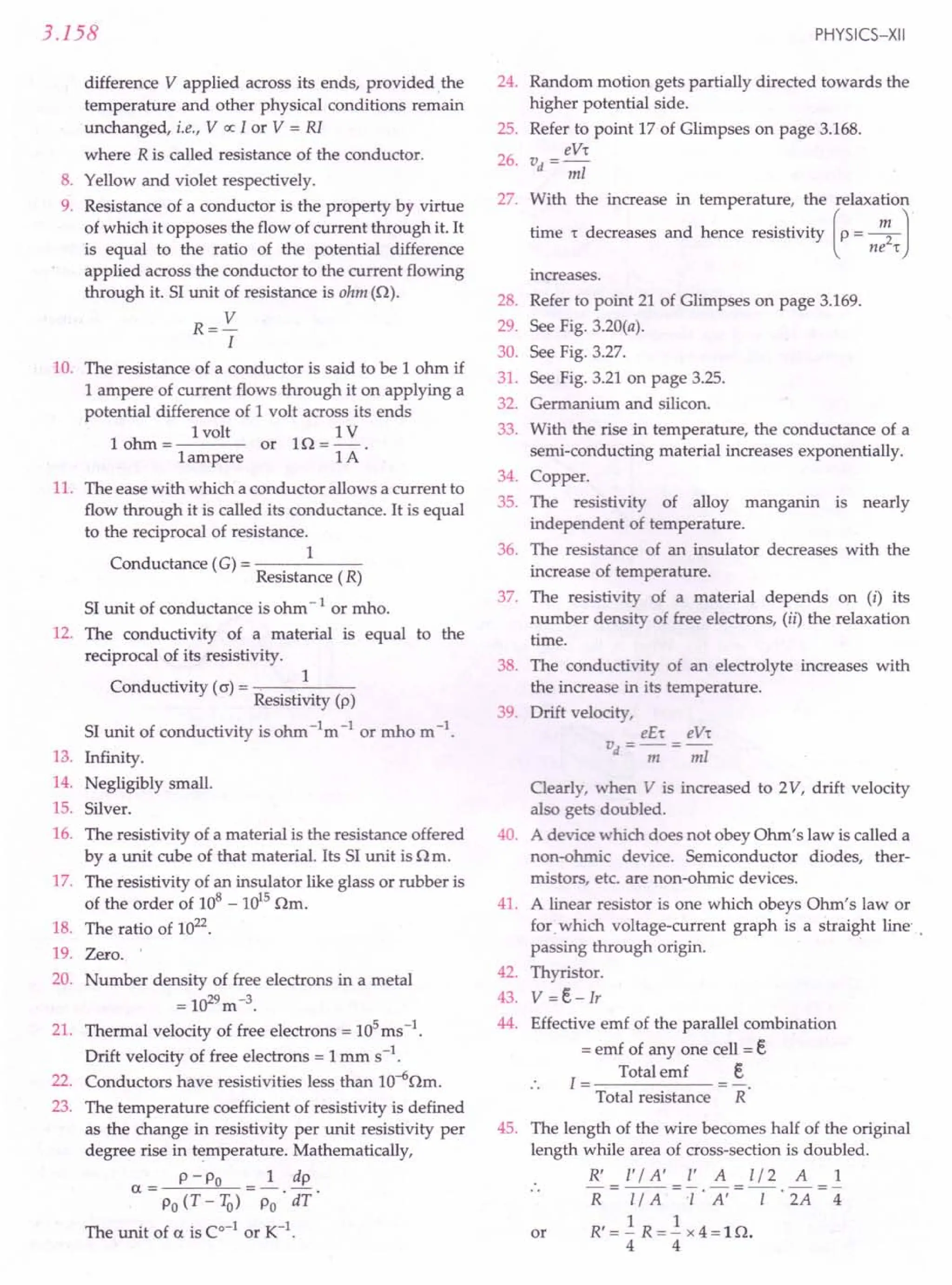
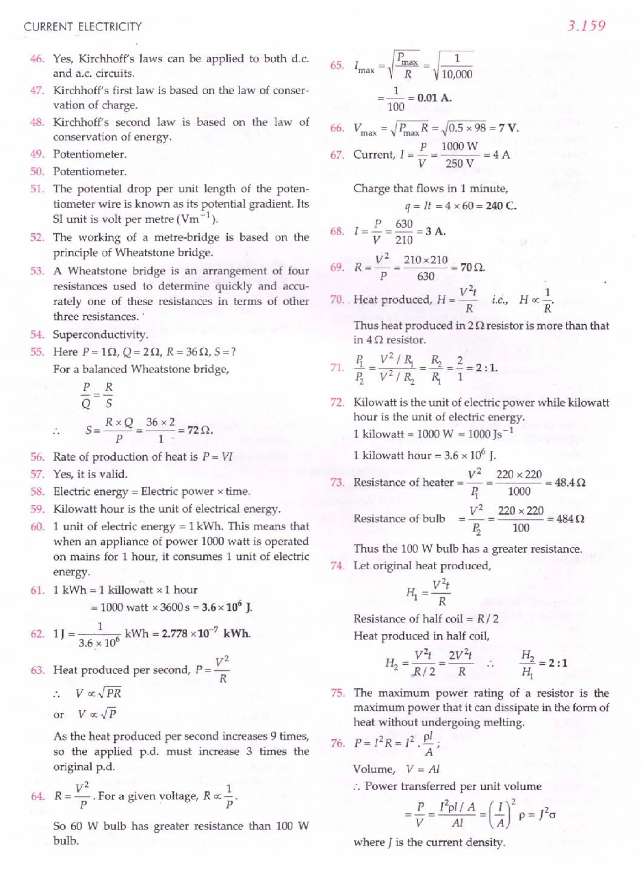
![3.160
77. A heater wire should have
(i) high melting point, and
(ii) high resistivity.
78. A fuse wire must have high resistivity and low
melting point.
79. The melting point of a heater wire is very high
while that of a fuse wire is very low.
80. Total power P dissipated by the series combination
is given by
1 1 1 1 1 1
-=-+-=--+--=-
P ~ ~ 1000 1000 500
or P= SOOW.
81. The resistivity p at any temperature T is given by
p =Po [1+ a(T -1Q))
where Po is the resistivity at a lower reference
temperature 1Qand a is the temperature coefficient
of resistivity.
82. Total emf of three cells in series
= P.D. corresponding to zero current = 6 V
•.The emf of each cell = ~ = 2 V.
3
83. In the case of series combination of the two given
resistors, the the terminal p.d. will have a higher
value.
84. At higher values of current, the resistor gets heated
up and its resistance increases. The resistor
becomes non-ohmic and hence I-V graph deviates
from the straight line.
PHYSICS-XII
I
85. For each slab, R =p-
A
21 1 R
Rl =PA=2R ~ =p 2A =2
Rl = 2R =4: 1.
». R/2
r -_(t-VV] R.
86. Internal resistance,
t1'2 + t21
R('t + '2)+ 1'2
88. When the external resistance in the circuit is zero,
the current drawn from the secondary cell is max.
t
lmax =-
r
89. The internal resistance of a cell depends on
(i) the nature of the electrolyte and
(il) concentration of the electrolyte.
90. The sensitivity of a potentiometer depends on the
potential gradient along its wires. This, in turn,
depends on (I) length of the potentiometer wire and
(ii) the value of resistance put in series with the
driver cell.
91. (i) In the region DE. I decreases with increasing V.
+ve~V
---= -veR
=ve Sl
(i!) AB/ BCis the region where Ohm's law is obeyed.
~YPE B : SHORT ANSWER QUESTIONS (2 or 3 marks each)
1. Distinguish between electromotive force and
terminal potential difference of a cell. What are their
units? [CBSE 00 14C]
2. Explain how the average velocity of free electrons
in a metal at constant temperature, in an electric
field, remains constant even though the electrons
are being constantly accelerated by this electric
field?
3. Define the terms resistivity and conductivity and
state their 51 units. Draw a graph showing the
variation of resistivity with temperature for a
typical semiconductor. [CBSE 0 05]
4. Define the electrical resistivity of a material. How it
is related to the electrical conductivity ? Of the
factors, length, area of cross-section, nature of
material and temperature - which ones control the
resistivity value of conductor? [CBSE F 98]
5. Explain the term 'drift velocity' of electrons in a
conductor. Hence obtain the expression for the
current through a conductor in terms of 'drift
velocity'. [CBSE 00 13, 13C, lSC]
6. Prove that the current density of a metallic
conductor is directly proportional to the drift speed
of electrons. [CBSE 0 08]
7. What is meant by drift velocity of free electrons?
Derive Ohm's law on the basis of the theory of
electron drift. [CBSE 0 03; Haryana 94]
8. Are the paths of electrons straight lines between
successive collisions (with positive ions of the
metal) in the (i) absence of electric field (ii) presence
of electric field ? Establish a relation between drift
velocity 'v/ of an electron in a conductor of cross-
section' A', carrying current' l' and concentration](https://image.slidesharecdn.com/slaroraclass12thphysicsbyrockytrickster-250318042948-c8b51a5a/75/SL-ARORA-CLASS-12TH-PHYSICS-BY-ROCKY-TRICKSTER-pdf-313-2048.jpg)
![CURRENT ELECTRICITY
'n' of free electrons per unit volume of conductor.
Hence obtain the relation between current density
and drift velocity. [CBSE aD 03]
9. Define relaxation time of electrons in a conductor.
Explain how it varies with increase in temperature
of a conductor. State the relation between resistivity
and relaxation time. [CBSE D 2000]
10. A conductor of length 'I' is connected to a d.c.
source of potential 'V'. If the length of the
conductor is tripled, by stretching it, keeping 'V'
constant, explain how do the following factors vary
in the conductor:
(i) Drift speed of electrons, (ii) Resistance and
(iii) Resistivity. [CBSE D 2000]
11. Write the mathematical relation between mobility
and drift velocity of charge carri~rs in a conductor.
Name the mobile charge carriers responsible for
conduction of electric current in
(i) an electrolyte (ii) an ionised gas. [CBSE D 06]
12. Define the term current density of a metallic
conductor. Deduce the relation connecting current
density 0) and the conductivity (o) of the
conductor, when an electric field E, is applied to it.
[CBSE D 06]
13. Define ionic mobility. Write its relationship with
relaxation time. Give its S1 unit. How does one
understand the temperature dependence of resis-
tivity of a semiconductor. [CBSE F 10; oo 13C]
14. Definethe terms (I) drift velocity, (ii) relaxationtime.
A conductor of length L is connected to a de source
of emf e. If this conductor is replaced by another
conductor of same material and same area of
cross-section but of length 3L, how will the drift
velocity change? [CBSE D 11]
15. Define relaxation time of the free electrons drifting
in a conductor. How is it related to the drift velocity
of free electrons? Use this relation to deduce the
expression for the electrical resistivity of the
material. [CBSE on 12]
16. Define the term resistivity of a conductor. Give its
S1unit. Show that the resistance of a conductor is
given by
where the symbols have their usual meanings.
[CBSE co 02]
17. Define resistivity of a conductor. Plot a graph
showing the variation of resistivity with tempe-
rature for a metallicconductor.How does one explain
such a behaviour, using the mathematical expression
of the resistivity of a material. [CBSE D 01, 08]
3.161
18. Draw a plot showing the variation of resistivity of a
(i) conductor and (ii) semiconductor, with the
increase in temperature.
How does one explain this behaviour in terms of
number density of charge carriers and the
relaxation time ? [CBSE D 14C]
19. Define conductivity of a conductor and state its S1
unit. Stateand explain the variation of conductivityof
(a) good conductor (b) ionic conductor with
temperature. [CBSE D 01, 08]
20. Establish the relation between drift velocity of
electrons and the electric field applied to the
conductor. [Punjab02]
Or
Derive an expression for drift velocity of free
electrons in a conductor in terms of relaxation time.
[CBSE D 09, on 15]
21. Establish a relation between current and drift
velocity. [Himachal
03; CBSE on 15C]
22. Define the term resistance. Give physical expla-
nation of the opposition offered by a conductor to
the flow of current through it. [Haryana94]
23. Explain the colour code for carbon resistors with
illustrations. [Haryana95, 98]
24. Three resistances ~, Rz and ~ are connected in
series. Find their equivalent resistance. [CBSE D 92]
25. Three resistances ~, Rz and ~ are connected in
parallel. Find the equivalent resistance of the
parallel combination.
[CBSE D 92 ; Himachal98C ; Punjab03]
26. What is superconductivity ? Explain. State two
applications of superconductors. [Punjab03]
27. What are superconductors? Give two applications
of the phenomenon of superconductivity.
[Haryana94 ; Punjab95 ; CBSE F03]
28. What is Meissner effect ? What does it indicate
about the magnetic nature of superconductors?
29. What are ohmic and non-ohmic resistors? Give one
example of each. [Haryana02]
30. State the conditions under which Ohm's law is not
obeyed in a conductor. [CBSE D 92]
31. What is internal resistance of a cell ? On what
factors does it depend ?
32. Define emf of a cell. Show that the voltage drop
across a resistor connected in parallel with a cell is
different from the emf of the cell. [CBSE OD'94C]
33. When a battery of emf eand internal resistance r is
connected to a resistance R, a current I flows
through it. Derive the relation between e, I, r and R
[CBSE D 92]](https://image.slidesharecdn.com/slaroraclass12thphysicsbyrockytrickster-250318042948-c8b51a5a/75/SL-ARORA-CLASS-12TH-PHYSICS-BY-ROCKY-TRICKSTER-pdf-314-2048.jpg)
![3.162
34. Figure 3.330shows a cell of emf eand internal resis-
tance r, connected to a voltmeter V and a variable
resistance R Deduce the relationship among V, e, R
and r. How will V vary when R is reduced.
[ISCE98]
R
,
,
,
,
,
,
Y',,
,
v
Fig. 3.330
35. Define internal resistance of a cell. Prove that
where R is the external resistanceused. [Himachal99]
36. A cell of emf 'e' and internal resistance 'r is
connected across a variable load resistor R Draw
the plots of the terminal voltage V versus (i) Rand
(ii) the current I. [CBSE
0 15]
37. Distinguish between emf (e) and terminal voltage
(V) of a cell having internal resistance 'r . Draw a
plot showing the variation of terminal voltage (V)
vs. the current (I) drawn from the cell. Using this
plot, how does one determine the emf and the
internal resistance of the cell? [CBSE
00 14,14C]
38. A cell of emf eand internal resistance r is connected
across a variable resistance R Plot graphs showing
the variation of (i) eand R,(ii) terminal p.d. V with
R Predict from the second graph under which V
becomes equal to e. [CBSE
0 09]
39. Two identical cells, each of emf e and internal
resistance r are connected in parallel to an external
resistance R Find the expression for the total
current flowing in the circuit. [CBSE
F 96]
40. Derive the formula for the equivalent EMF and
internal resistance for the parallel combination of
two cells with EMFs e1
and e2
and internal resis-
tances 1. and r2
respectively. What is the corres-
ponding formula for the series combination ?
[CBSE
SamplePaper08]
41. Name anyone material having a small value of
temperature coefficient of resistance. Write one use
of this material. [CBSE
0 97]
42. Define the terms electric energy and electric power.
Give their units. [Haryana92; Punjab93]
43. Obtain the formula for the 'power loss' in a
conductor of resistance R, carrying a current I.
[CBSE
D 09C]
44. Two heating elements of resistances ~ and Rz
when operated at a .constant supply of voltage, V,
PHYSICS-XII
consume powers ~ and Pz respectively. Deduce the
expressions for the power of their combination
when they are, in turn, connected in (i) series and
(ii) parallel across the same voltage supply.
[CBSE
0011]
45. Give four reasons why nichrome element is
commonly used in household heating appliances.
46. What is a safety fuse? Explain its function.
[Punjab99]
47. State the two Kirchhoff's rules used in electric
networks. How are these rules justified ?
[CBSE
0 14,00 15]
48. State the working principle of a potentiometer.
Explain, with the help of a circuit diagram, how the
emfs of two primary cells are compared by using a
potentiometer. How can the sensitivity of a
potentiometer be increased ?
[CBSE
0 05,06C; 00 15C]
49. Statethe principle of a potentiometer.With the help of
a circuit diagram, describe a method to find the inter-
nal resistance of a primary cell.
[CBSE
0 03; 00 13]
50. You are required to find the internal resistance of a
primary cellin the laboratory. Draw a circuit diagram
of the apparatus you will use to determine it. Explain
the principle of the experiment. Give the formula
used. [CBSE
0 08C]
51. Why is the use of a potentiometer preferred over
that of a voltmeter for the measurement of emf of a
cell ? [Himachal01]
52. Use Kirchhoff's rules to obtain conditions for the
balance condition in Wheatstone bridge.
[CBSE
015]
53. For the circuit diagram of a Wheatstone bridge
shown in the figure, use Kirchhoff's laws to obtain
its balance condition. [CBSE
0 09C]
+
Fig. 3.331
54. State, with the help of a suitable diagram, the
principle on which the working of a metre bridge is
based. Under what condition is the error in
determining the unknown resistance minimized ?
[CBSE
F 10,13,00 15C]](https://image.slidesharecdn.com/slaroraclass12thphysicsbyrockytrickster-250318042948-c8b51a5a/75/SL-ARORA-CLASS-12TH-PHYSICS-BY-ROCKY-TRICKSTER-pdf-315-2048.jpg)
![CURRENT ELECTRICITY
55. Draw a circuit diagram which can be used to deter-
mine the resistance of a given wire. Explain the
principle of the experiment and give the formula
used. [eBSE 0 03C]
56. Draw a circuit diagram using a metre bridge and
write the necessary mathematical relation used to
determine the value of an unknown resistance.
Why cannot such an arrangement be used for
measuring very low resistances? [eBSE 0 06]
Answers
3.163
57. Draw a circuit diagram of a metre bridge to
compare two resistances. Write the formula used.
Why is this method suitable only for two resistances
of the same order of magnitude? [eBSE F 99]
58. Derive an expression for the heat produced in a
resistor R when voltage drop across it is V.
[eBSE F 93]
••
1.
EMF Terminal Voltage
(i) It is the potential dif- It is the potential dif-
ference between two ference between two
terminals of the cells terminals when a
when no current is current passes through
drawn from it. it.
(ii) It is a cause. It is an effect.
(iii) The SI unit is volt. The SI unit is volt.
2. Refer to the solution of Problem l(b) on page 3.122.
3. Refer to points 10 and 13 of glimpses on page 168.
4. Resistivity of a material is the resistance of a
conductor of that material having unit length and
unit area of cross-section.
C d
.. 1
on uctivity = ----
Resistivity
Resistivity of conductor depends on the nature of
its material and its temperature.
5. Refer answer to Q. 19 on page 3.16
6. Refer answer to Q. 19 on page 3.16.
7. Refer answer to Q. 19 on page 3.16.
8. Refer answer to Problem l(e) on page 3.122 and
Q. 19 on page 3.16.
9. The average time that elapsesbetween two successive
collisions of an electron in a conductor is called
relaxation time (r), It is rE!latedto resistivity p as
m
P=-2-'
ne 't
With the increase in temperature, the electrons
collide more frequently with positive metal ions. So
their relaxation time decreases.
Drift speed, vd = eV r : Resistance, R = p..£..
ml A
When I is tripled
(i) drift-speed becomes 1/3 times the original vd
(ii) resistancebecomes3 times the originalresistance
(iii) resistivity is not affected.
10.
11. Mobility = Drift velocity
Electric field
or
v
Jl =--.!L
E
(i) The charge carriers in an electrolyte are
positive and negative ions. ,
(ii) The charge carriers in an ionised gas are
electrons and positively charged.
12. Refer answer to Q. 12 on page 3.7
13. Refer to point 21 of Glimpses.
Resistivity, p = ~
ne 't
As temperature increases,average speed ofelectrons
increases. This increases collision frequency and
decreases relaxation time 'to But n increases more
rapidly with temperature. The increase in n more
than compensates the decrease in 'to So p of
semiconductors decreases with temperature.
14. Refer to point 17 of Glimpses.
ee
vd = mL't
When length is increased to 3L, drift velocity
becomes 1/3 times the original vd
.
15. Refer answer to Q. 19 on page 3.16.
16. Refer answer to Q. 19 on page 3.16.
17. Resistivity of a material is the resistance of a
conductor of that material having unit length and
unit area of cross-section. The SIunit of resistivity is
ohm metre (am).
Resistivity of a conductor = ~
ne 't
With the increase in temperature, the amplitude of
vibration of positive ions increases. The electrons
suffer collisions more frequently. The relaxation
time r decreases. Hence the resistivity of a
conductor increases with the increase in
temperature.
18. Refer answer to Q. 25 on page 3.24.
19. The conductivity of a conductor is the reciprocal of
its resistivity. Its SI uni] is a-1
m -1.](https://image.slidesharecdn.com/slaroraclass12thphysicsbyrockytrickster-250318042948-c8b51a5a/75/SL-ARORA-CLASS-12TH-PHYSICS-BY-ROCKY-TRICKSTER-pdf-316-2048.jpg)
![3.164
The conductivity of an ionic conductor increases
with the increase of temperature. As the tempe-
rature Increases, the electrostatic attraction between
cations and anions decreases, the ions are more free
to move and so the conductivity increases.
20. Refer answer to Q. 18 on page 3.15.
21. Refer answer to Q. 19 on page 3.16.
22. Refer answer to Q. 21 on page 3.17.
23. Refer answer to Q. 15 on page 3.9.
24. Refer answer to Q. 32 on page 3.30.
25. Refer answer to Q. 33 on page 3.31.
26. Refer answer to Q. 28 on page 3.29.
27. Refer answer to Q. 30 on page 3.30.
28. Refer answer to Q. 29 on page 3.29.
29. Refer answer to Q. 27 on page 3.28.
30. Refer answer to Q. 27 on·page 3.28.
31. Refer answer to Q. 34 on page 3.45.
32. Refer answer to Q. 35 on page 3.46.
33. Refer answer to Q. 35 on page 3.46.
34. Refer answer to Q. 35 on page 3.46.
eR e
We get V = R + r = 1+ (r / R)
Clearly V decreases when R is reduced.
35. Refer answer to Q. 35 on page 3.46.
36. (i) See Fig. 3.91(b) (ii) See Fig. 3.91(c) on page 3.46.
37. Refer answer to Q. 35 on page 3.46.
38. Refer answer to Q. 35 on page 3.46.
e e 2Re
39. 1= =--=--
R+ _r_x_r
r+ r
R+ r
2
2R+ r
40. Referto the answers ofQ. 37,38 on pages 3.51& 3.52.
PHYSICS-XII
41. Alloy like manganin has a small value of tempe-
rature coefficient of resistivity. It is used for making
standard resistances.
42.
43.
44.
45.
46.
47.
48.
49.
• 50.
51.
52.
53.
54.
Referanswer to Q.44 and Q. 45. on pages 3.60 & 3.61.
Refer answer to Q. 44 on page 3.60.
Refer to answers of Q. 47, 48 on page 3.61 & 3.62.
Refer answer to Q. 54 (Application 1) on page 3.64.
Refer answer to Q. !?4(Application 3) on page 3.64.
Refer to point 47 of Glimpses on page 3.172.
Refer answers to Q. 57 and Q. 58 on page 3.96.
Refer answer to Q. 59 on page 3.97.
Refer answer to Q. 59 on page 3.97.
Refer answer to Q. 60 on page 3.97.
Refer answer to Q. 62 on page 3.104.
Refer answer to Q. 62 on page 3.104. ...--- .
See Fig. 3.213. The working of a metre bridge is
based on the principle of Wheatstone bridge. When
the bridge is balanced i.e., no current flows through
P R
the galvanometer arm, - =-
Q 5
55.
56.
Error in determination of resistance can be
minimised by adjusting the balance point near the
middle of the metre bridge wire.
Refer answer to Q. 65 on page 3.105.
Refer answer to Q. 65 on page 3.105.
Metre bridge becomes insensitive for very low
resistance. Moreover, the end resistances become
comparable to the unknown low resistance and
cannot be neglected.
Refer answer to Q. 65 on page 3.105 and Problem 71
on page 3.120.
Refer answer to Q. 43 on page 3.60.
57.
58.
~YPE C: LONG ANSWER QUESTIONS (5 marks, each)
1. Define the term resistivity and write its SI unit. 5. A mixed grouping of cells has m rows of cells
Derive the expression for the resistivity of a connected in parallel across an external
conductor in terms of number density of free resistance R. Each row contains n cells in series.
electrons and relaxation time. [CBSE D 05] Each cell has emf e and iriternal resistance r.
2. What do you understand by the resistivity of a Show that the current in the circuit will be
conductor ? Discuss its temperature dependence maximum when R = nr/ m.
for a (i) conductor (ii) semiconductor, and 6. State Kirchhoff's laws for an electrical network.
(iii) electrolyte. [CBSE D92C]
3. A battery of n cells, each of emf e and internal
resistance r, is connected across an external
resistance R.Find the current in the circuit. Discuss
the special cases when (i) R» nrand (ii) R« nr.
4. n cells, each of emf e and internal resistance rare
connected in parallel across an external resistance
R.Determine the condition for maximum current in
the circuit.
Using Kirchhoff's laws, find the relation between
the resistances of four arms of a Wheatstone bridge
when the bridge is balanced.
Draw a circuit diagram to determine the unknown
resistance of a metallic conductor using a metre
bridge. [CBSE OD03C ; D 13]
7. Define the term potential gradient. Using this
concept, explain the method for comparison of](https://image.slidesharecdn.com/slaroraclass12thphysicsbyrockytrickster-250318042948-c8b51a5a/75/SL-ARORA-CLASS-12TH-PHYSICS-BY-ROCKY-TRICKSTER-pdf-317-2048.jpg)
![CURRENT ELECTRICITY
emfs of two primary cells using a potentiometer.
Establish the relation used. Write two possible
causes of potentiometer giving only one-sided
deflection.· [CBSE
D13]
8. (a) State the working principle of a potentiometer.
Draw a circuit diagram to compare the emfs of two
primary cells. Derive the fonriula used. (b) Which.
material is used for potentiometer wire and why?
(c) How can the sensitivity of a potentiometer be
increased? [CBSE
D 11C]
9. Deduce the condition for balance in a Wheatstone
bridge. Using the principle of Wheatstone.bridge,
describe the method to determine the specific·
Answers
3.165
resistance of a wire in the laboratory. Draw the
circuit diagram and write the formula used. Write
any two precautions you would observe while
performing the experiment. [CBSE
D 04]
10. (a) State, with the help of a circuit diagram, the
working principle of a. metre bridge. Obtain
the expression used for determining the
unknown resistance.
(b) What happens if the galvanometer and cell are
interchanged at the balance point of the bridge?
(c) Why it is considered important to obtain the
balance point near the midpoint of the wire?
[CBSE
D 11C]
•
1. Refer answer to Q. 19 on page 3.16.
2. Refer answer to Q. 25 on page 3.24.
3. Refer answer to Q. 39 on page 3.53.
4. Refer answer to Q. 40 on page 3.53.
5. Refer answer to Q. 41 on page 3.54.
6. Refer answer to Q. 62 on page 3.104 and see
Fig. 3.214 on page 3.106.
7. Refer answer to Q. 58 on page 3.96 and Problem 42
on page 3.142. (c)
~YPE D : VALUE BASED QUESTIONS (4 marks each)
1. Mrs. Sharma parked her car and forgot to switch off
the car headlights. When she returned, she could
not start the car. Rohit, a passerby, came to her for
help. After knowing about her problem, he went to
a nearby garage and called mechanic Ramu. Ramu
noticed that the car battery has been discharged as
the headlights were left on for a long time. He
brought another battery from his garage and
connected its terminals to the terminals of the car
battery. He succeeded in starting the engine and
then disconnected his battery. This is called 'jump
starting', Mrs. Sharma felt happy and thanked both
Rohit and Ramu. Answer the following questions
based on the above information:
(a) What values were displayed by Rohit ?
(b) A storage battery of emf 12 V and internal
resistance 0.5 n is to be charged by a battery
charger which supplies 110 V de. How much
resistance must be connected in series with the
battery to limit the charging current to 5 A.
What will be the p.d. across the terminals of
the battery during charging ? What is the
purpose of having a series resistor in the
charging circuit?
8. (a) Refer answer to Q. 57 and Q. 58 on page 3.96.
(b) Referto the solution ofProblem49 on page 3.119.
(c) Referto the solution ofProblem56 on page 3.119.
9. Refer answers to Q. 62 on page 3.104 and Q. 65 on
page 3.105.
10. (a) Refer answer to Q. 65 on page 3.105.
(b) There is no change in the position of the
balance of the bridge.
Referto the solutionofProblem 65 on page 3.119. ,
2. Manish and Rajnish lived in an unauthorised
colony. They found that most people of that colony
stole power from transmission lines using hooks.
They had read in the newspapers about different
fire accidents caused due to electric short circuits.
Alongwith some of their friends and some respon-
sible representatives of that area, they visited house
to house of that colony and made people aware of
the risks involved in short circuiting. They also
explained the people the importance of paying
electricity bills. They succeeded in changing the
mindset of the people. Answer the following
questions based on the above information:
(a) What according to you, are the values of
displayed by Manish and Rajnish ?
(b) A household circuit has a fuse of 5 A rating.
Find the maximum number of bulbs of rating
60 W - 220 Veach which can be connected in
this circuit.
3. Abhishek went to meet his grandfather who lived
in a village. Both were resting and gossiping under
a fan to get relief from the scorching heat of
summer. The lights suddenly went off. On seeing
that, that all their neighbourers had electricity,](https://image.slidesharecdn.com/slaroraclass12thphysicsbyrockytrickster-250318042948-c8b51a5a/75/SL-ARORA-CLASS-12TH-PHYSICS-BY-ROCKY-TRICKSTER-pdf-318-2048.jpg)
![3.166
grandfather told Abhishek the fuse might have
blown up. Abhishek immediately changed the fuse.
Grandfather blessed Abhishek and told him that if
had he not come to the village, he would have to
sleep the whole night without fan. Abhishek realised
his grandfather's problem and decided to replace
the fuse with a circuit breaker which uses a solenoid
with a core. When the current exceeds a safety limit,
the breaker is activated and thus breaks the circuit.
The circuit can be closed by a manual switch.
Answer the following questions based on the above
information:
(a) What were thevalues displayed by Abhishek?
(b) A low voltage supply from which one needs
high current must have very high internal
resistance. Why ?
4. Ameen had been getting huge electricity' bill for the
. : past few months. He was upset about this. One day
Answers
PHYSICS-XII
his friend Rohit, an electrical engineer by
profession, visited his house. When he pointed out
his anxiety about this to Rohit, his friend found that
Ameen was using traditional incandescent lamps
and using old fashioned air conditioner. In addition
there was no proper earthing in the house. Rohit
advised him to use CFL bulbs of 28 W instead of
1000 W - 220 V and also advised him to get proper
earthing in the house. He made some useful
suggestion and asked him to spread this message to
his friends also. reBSE DISC]
(a) What qualities/values, in your opinion did
Rohit possess ?
(b) Why CFLs and LEDs are better than traditional
incandescent lamps?
(c) In what way earthing reduces electricity bill ?
1. (a) Helpful, aware of his limits, ability to take quick
decisions.
(b) Net emf, e = 110-12 = 98V
If R is the series resistor, then the charging current
will be
I = _E_ = ~ A = 5 A (given) :. R = 19.1 n
R+ r R+ 0.5
Terminal p.d. of the battery during charging,
V = E+ Ir = 12+ 5 x 0.5 = 14.5 V
If the series resistor R were not included in
charging circuit," the charging current would be
~ = 196A, which is dangerously high.
0.5
2. (a) Critical thinking, decision making, team spirit
and assertive communication.
P 60 3
(b) Current drawn by one bulb = - = - = - A
V 220 11
Number of bulbs that can be safely used with
5 A fuse = _5_ = 55 = 18.33
3/11 3
Hence 18bulbs can be safely used with 5 A fuse.
3. (a) Empathy, dutifulness, determination, responsi-
bility and compassion.
(b) The maximum current that can be drawn from
a voltage supply is given by
E
Imax
r
Clearly, Imax
will be large if r is small.
4. (a) Helpfulness, co-operative attitude and scientific
temperament.
(b) CFLs and LEDs have following advantages:
(i) Low operational voltage and less power
consumption.
(ii) Fast action and require no warm up time.
(c) In the absence of proper earthing, the
consumer can get extra charges in his bill for
the electrical energy not actually consumed by
his/her devices.](https://image.slidesharecdn.com/slaroraclass12thphysicsbyrockytrickster-250318042948-c8b51a5a/75/SL-ARORA-CLASS-12TH-PHYSICS-BY-ROCKY-TRICKSTER-pdf-319-2048.jpg)
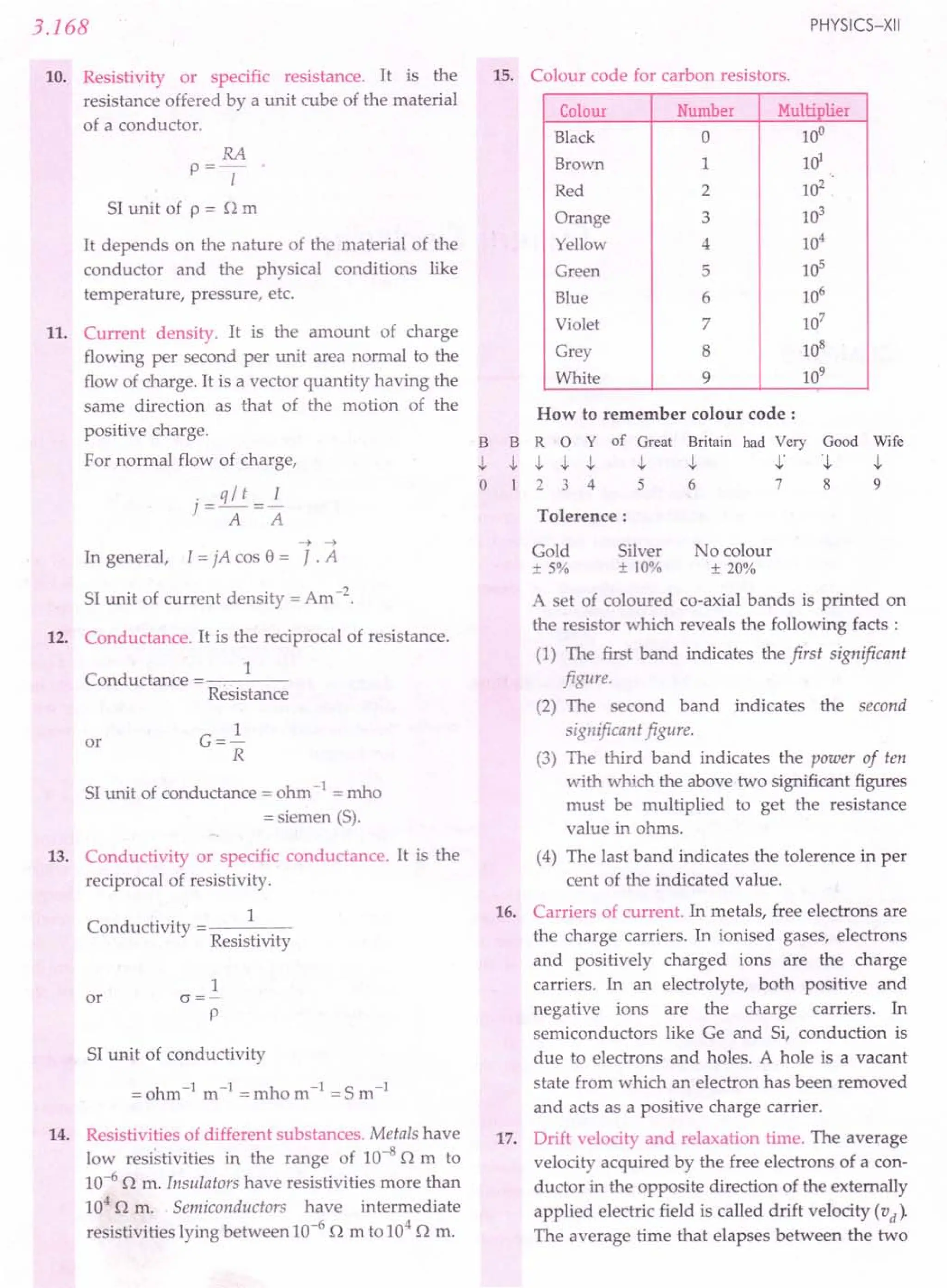
![3.170
27 ... Resistances in series. When a number of
resistances are connected in series, their
equivalent resistance (Rs) is equal to the sum of
the individual resistances.
Rs =Rl +~ +~ +...
28. Resistances in parallel. When a number of
resistances are connected in parallel, the
reciprocal of their equivalent resistance (Rp) is
equal to the sum of the reciprocals of the
individual resistances.
111 1
-=-+-+-+ ...
Rp Rl ~ ~
For two resistances in parallel,
R = Rl~
P Rl + ~
29. Division of current in resistors joined in
parallel. The current is divided in resistors,
connected in parallel, in the inverse ratio of
their resistances.
I = ~ . I
1 Rl + ~
1= Rl .1
2 Rl + ~
30. Internal resistance (r). The resistance offered by
the electrolyte of a cell to the flow of current
between its electrodes is called internal
resistance of the cell. It depends on (i) nature of
the electrolyte, (ii) concentration of the
electrolyte, (iii) distance between the electrodes,
(iv) common area of the electrodes dipped in the
electrolyte and (v) temperature of the
electrolyte.
Relations between emf (e) , terminal potential
difference (V) and internal resistance (r). The
potential drop across the terminals of a cell
when a current is being drawn from it is called
its terminal potential difference. It is less than
the emf of the cell in a closed circuit.
31.
V=IR=~
R+r
r=e-V=R[e-V]'I=_e_'I =~
I V' R+r'max r
e = V + Ir ; V = e- Ir ;
Terminal p.d. of a cell when it is being charged
is
PHYSICS-XII
32. Cells in series. If, n cells of emf e ~d internal
resistance r each are connected in series, then
current drawn through external resistance R is
I=~
R + nr
33. Cells in parallel. If m cells are connected in
parallel, then current drawn through external
resistance R is
I=~
mR+r
34. Cells in mixed grouping. If n cells are connected
in series in each row and m such rows are
connected in parallel, then current drawn
through an external resistance R is
mne
1=---
mR+ nr
For maximum current, the external resistance
must be equal to the total internal resistance, i.e.,
R = I1r
m
or mR = nr.
35. Heating effect of current. The phenomenon of
the production of heat in a resistor by the flow
of an electric current through it is called heating·
effect of current or Joule heating. It is an
irreversible process.
Joule's law of heating. It states that the amount
of heat H produced in a resistor is
(i) directly proportional to the square of
current for a given R,
(ii) directly proportional to the resistance R for
a given I,
(iii) inversely proportional to the resistance R
for a given V, and'
(iv) directly proportional to the time t for which
the current flows through the resistor.
Mathematically, this law can be expressed as
H = VIt joule
,. . V2t
= 12Rt joule = Rjoule.
H = VIt cal
4.18
36.
or
12Rt V2
t
= -- cal = --- cal.
4.18 4.18R](https://image.slidesharecdn.com/slaroraclass12thphysicsbyrockytrickster-250318042948-c8b51a5a/75/SL-ARORA-CLASS-12TH-PHYSICS-BY-ROCKY-TRICKSTER-pdf-323-2048.jpg)
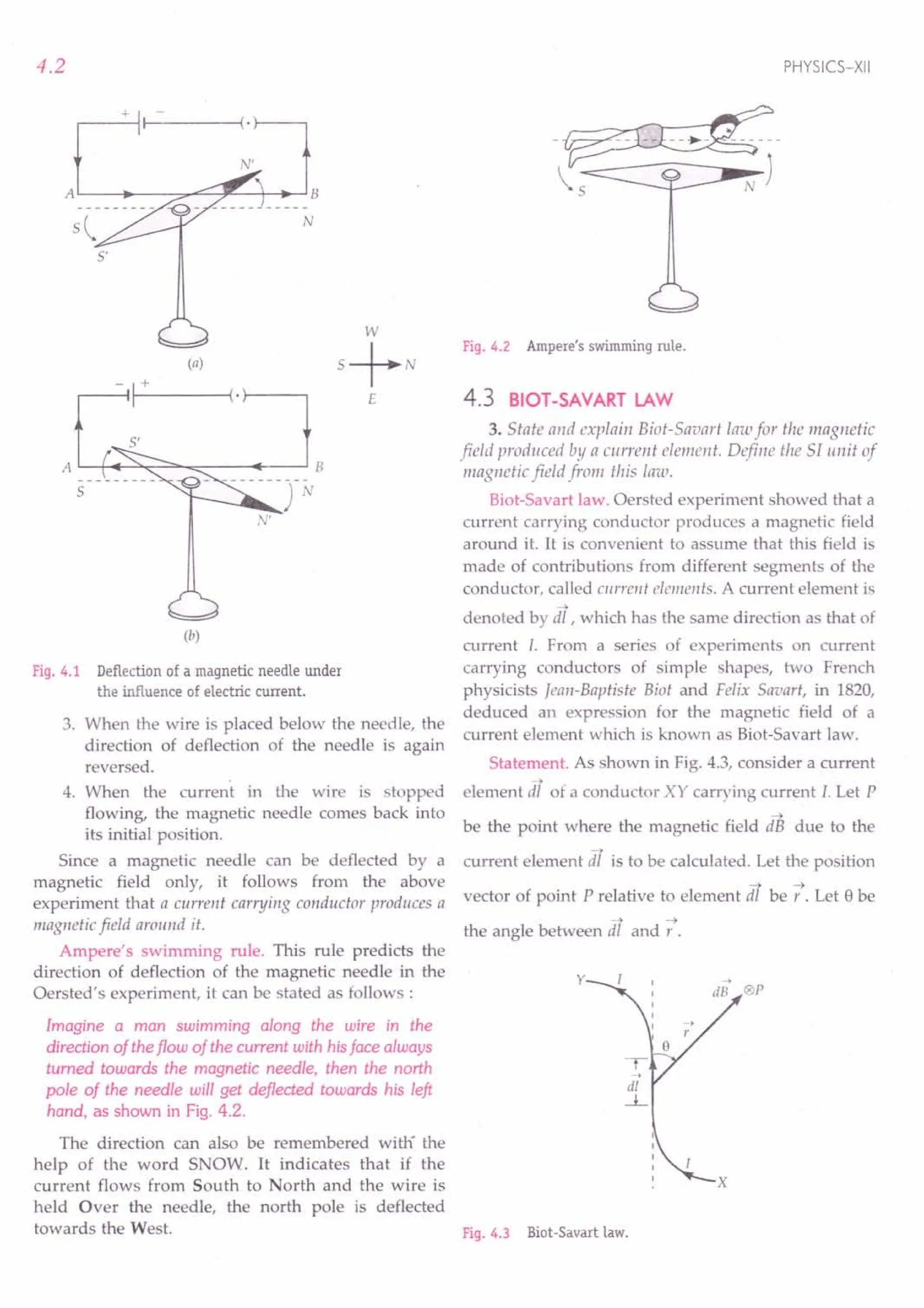
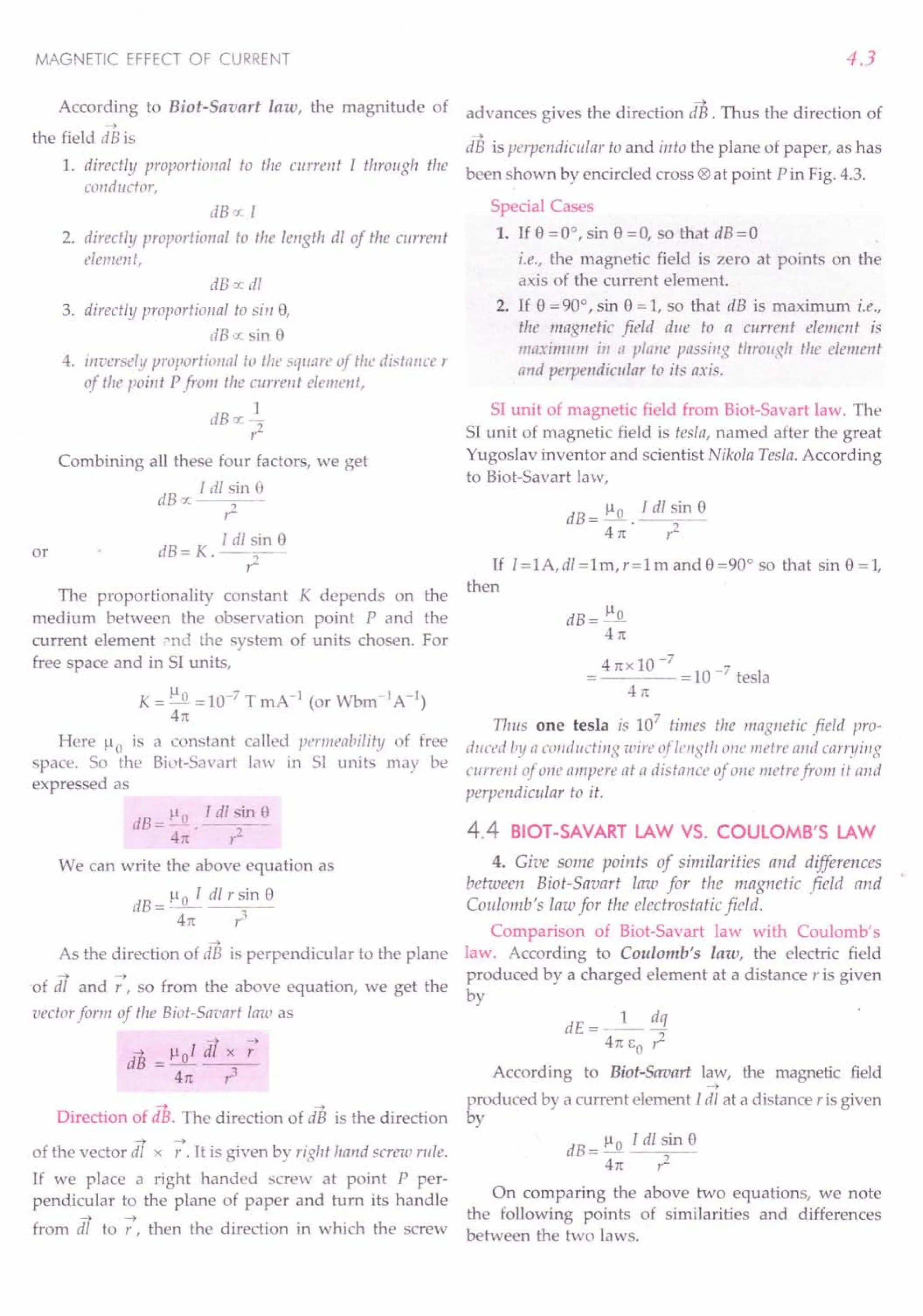
![4.4
Points of similarity :
1. Both fields depend inversely on the square of
the distance from the source to the point of
observation.
2. Both are long range fields.
3. The principle of superposition is applicable to
both fields. This is because the magnetic field is
linearly related to its source, namely, the current
element [ dl and the electrostatic field is related
linearly to its source, namely, the electric charge.
Points of difference :
1. The magnetic field is produced by a vector
....•
source : the current element l dl . The electro-
static field is produced by a scalar source: the
electric charge dq.
2. The direction of the electrostatic field is along
the displacement vector joining the source and
the field point. The direction of the magnetic
field is perpendicular to the plane containing
....•
the displacement vector r and the current
element [ dl.
3. In Bio-Savart law, the magnitude of the
magnetic field is proportional to the sine of the
angle between the current element [dl and
....•
displacement vector r while there is no such
angle dependence in the Coulomb's law for the
electrostatic field. Along the axial line of the
current element 8 =0°, sin 8 =0 and hence
dB=O.
5. Write a relation between ).L 0' E a and c.
Relation between ).Lo' EO and c. We know that
_1_ = 9 x 10⁹ Nm2 C-2
4n EO
and ).Lo= 10-7 Tm A-I
4rc
).L E =().L0)(4~J
o 0 4rc 1
= 10- 7 x _1_ = 1
9 x 10⁹
(3 x 10⁸
/
But 3 x 10⁸ ms -1 = speed of light in vacuum (c)
1
).Lo EO = 2
c
or
1
c=--~.
~).LoEO
PHYSICS-XII
Examples Based on
Formula Used
).L ldl sin e
Biot-Savart law, dB = ~ 2
4rc r
Units Used
Magnetic field B is in tesla, current I in ampere
and distance r in metre.
Constant Used
Permeability constant, ).Lo = 4rcx 10-7
Tm A-1
Example 1. A wire placed along the north-south direction
carries a current of 8 A from south to north. Find the
magnetic field due to a 1 cm piece of wire at a point 200 cm
north-east from the piece.
Solution. The problem is illustrated in Fig. 4.4.
5
Fig. 4.4
As the distance OP is much larger than the length
of the wire, we can treat the wire as a small current
element.
Here I = 8 A, dl = 1 cm = 1 x 10⁻² m,
r=200 cm =2 m, 8 =45°
dB = ).Lo . I dl sin 8
4n r2
4rcx 10-7
8 x 1x 10-2 x sin 45°
4rc 22
= 1.4 x 10⁻⁹ T.
The direction of the magnetic field at point P is
normally into the plane of paper.
••••• A
Example 2. An element ~ I = ~x i is placed at the origin
and carries a large current 1=10 A What is the magnetic
field on the y-axis at a distance of 0.5 m. ~x = 1 em
[NCERT]
Solution. Here dl = ~ = 1 em = 10-2m, 1=10 A,
r=y=O.5m, 8=90°, ).Lo/4rc=10-7TmA-1](https://image.slidesharecdn.com/slaroraclass12thphysicsbyrockytrickster-250318042948-c8b51a5a/75/SL-ARORA-CLASS-12TH-PHYSICS-BY-ROCKY-TRICKSTER-pdf-329-2048.jpg)
![-> A
3. An elementL'11 = L'1xi is placed at the origin (asshown
in Fig.4.6)and carries a current I = 2 A. Find out the
magnetic field at a point Pon the y-axis at a distance
of 1.0 m due to the element L'1x = 1cm. Give also the
direction of the field produced. [CBSE D 09C] F· 4 7
19. .
(Ans. 2 x1O-9
T, in + z-direction)
MAGNETIC EFFECT OF CURRENT
y
O.5m
~------------~~x
Fig. 4.5
According to Biot-Savart law,
dB = 1-10 Idl sin 8
41t r2
10- 7 x 10 x 10- 2 x sin 90°
(0.5)2
= 4 x 10⁻⁸
T
The direction of the field dB will be the direction of
vector dl x -:. But
-;t ~ 1 1 1 1 1
dl x r = Lll i x Y j = L'1x Y (i x j ) = Sx Y k
)
Hence field dB is in the + z-direction.
rproblems for Practice
1. A wire placed along east-west direction carries a
current of 10 A from west to east direction.
Determine the magnetic field due to a 1.8 cm piece
of wire at a point 300ernnorth-east from the piece.
(Ans. 1.4 x 10⁻⁹
T, normally out
of the plane of paper)
-> -> A
2. A small current element I dl , with dl = 2 k mm
and I = 2 A is centred at the origin. Find magnetic
->
field dB at the following points:
(i) On the x-axis at x = 3 m.
(Ans. 4.44 x 1O-11
J 1)
(ii) On the x-axis at x = - 6 m.
(Ans. - 1.11 x 1O-11
J 1)
(iii) On the z-axis at z = 3 m. (Ans.O)
4.5
y
p
I~
o
x'..••- - - - - --~-_------_ x
~
: !11
,
~
z
Fig. 4.6
HINTS
1. Proceed as in Example 1.
2. Proceed as in Example 2.
3. Proceed as in Example 2.
We shall now apply Biot-Savart law to calculate the
magnetic field due to (i) a straight current carrying
conductor and (ii) a circular current loop.
4.5 MAGNETIC FIELD DUE TO A LONG
STRAIGHT CURRENT CARRYING
CONDUCTOR
6. Apply Biot-Savart law to derive an expression for
the magnetic field produced at a point due to the current
flowing through a straight wire of infinite length. Also
draw the sketch of the magnetic field. State the rules used
for finding the direction of this magnetic field.
Magnetic field due to a long straight current
carrying conductor. As shown in Fig. 4.7, consider a
straight conductor XY carrying current I. We wish to
find its magnetic field at the point P whose
perpendicular distance from the wire is a i.e., PQ = a.
y ,
TQ a 'h", p
4>1 ,
'"
,
...• ,
I r ,
,
i,o ,
,
,
,
0 ,
,,
,
,
,
,
,
,
,
x'
Magnetic field due to a straight current
carrying conductor.](https://image.slidesharecdn.com/slaroraclass12thphysicsbyrockytrickster-250318042948-c8b51a5a/75/SL-ARORA-CLASS-12TH-PHYSICS-BY-ROCKY-TRICKSTER-pdf-330-2048.jpg)
![B= flOI [sin <l1+ sin <12]
4na .
This equation gives magnetic field due to a finite
wire in terms of the angles subtended at the Fig. 4.8
observation point by the ends of the wire.
4.6
Consider a small current element dT of the
~
conductor at O. Its distance from Q is I i.e., OQ = I. Let r
be the position vector of point P relative to the current
--> -->
element and e be the angle between dl and r.
According to Biot-Savart law, the magnitude of the or
~ -->
field dB due to the current element dl will be
dB = ~. I dl sin e
4n: ,z
or
From right 11 OQP,
e+~ =90°
o =900-~
sin e = sin (90° - ~) = cos ~
Also
a
cos <1>=-
r
or
a
r=--=asec<l>
cos <I>
I
tan <1>=-
a
As
I= a tan <I>
On differentiating, we get
dl = a sec2
<l>d<l>
Hence dB = ~ I(a sec
2
<I>
d<l» cos <I>
4 rt a2
sec2
<I>
p 1
dB= _0_ cos <l>d<l>
4na
According to right hand rule, the direction of the
magnetic field at the P due to all such current elements
will be in the same direction, namely, normally into the
~
plane of paper. Hence the total field B at the point P
due to the entire conductor is obtained by integrating
the above equation within the limits - <l1and <12.
cjI:z fl I ~
B= f dB=_o- f cos <l>d<l>
-Ij; 4na - <h
or
Il I '"
= _0_ [ sin <I>
]:2
4n:a <h
~l 1
= _0_ [ sin <12- sin (- <l1) ]
4n:a
or
PHYSICS-XII
Special Cases
1. if the conductor XY is infinitely long and the point P
lies near the middle of the conductor, then <1= <12= rt / 2.
B = ~~ [sin 90° + sin 90°]
4n:a
Ilo 1
B=-
2n:a
2. If the conductor XY is infinitely long but the point P
lies near the end Y (or X), then <1=90° and <12=0°.
Il I Il 1
B= _0_ [sin 90° + sin 001 =_0_.
4na 4na
Clearly, the magnetic field due to an infinitely long
straight current carrying conductor at its one end is
just half of that at any point near its middle, provided
the two points are at the same perpendicular distance
from the conductor.
3. If the conductor is of finite length L and the point
Plies 011 its perpendicular bisector, then <l1= <12= <I>
and
sin <I>
= _ Ll2 = L
~a2 + (L/2)2 ~4a2 + L2
B= Ilo I [sin <1>+sin o]
4na
_ Ilo I 2L
- 4na . ~4a2 + i3
B= floIL .
2naJ4a2 + z3
or
Direction of magnetic field. For an infinitely long
conductor,
i.e.,
B= Ilol
2n:a
1
Boc-
a
Clearly, the magnitude of the magnetic field will be
same at all points located at the same distance from the
conductor. Hence the magnetic lines of force of a straight
(a) (b)
Magnetic lines of foce of a straight current
carrying conductor.](https://image.slidesharecdn.com/slaroraclass12thphysicsbyrockytrickster-250318042948-c8b51a5a/75/SL-ARORA-CLASS-12TH-PHYSICS-BY-ROCKY-TRICKSTER-pdf-331-2048.jpg)
![MAGNETIC EFFECT OF CURRENT
current carrying conductor are concentric circles with the
wire at the centre and in a plane perpendicular to the wire.
[A line of force is a curve, the tangent to which at any
point gives the direction of magnetic field at that
point]. If the current flows upwards, the lines of force
have anticlockwise sense [Fig. 4.8(a)] and if the current
flows downwards, then the lines of force have
clockwise sense [Fig. 4.8(b)].
Rules for finding the direction of magnetic field
due to straight current carrying conductor. Either of
the following two rules can be .used for this purpose:
1. Right hand thumb rule. If we hold the straight
conductor in the grip of our right hand in such a way that
the extended thumb points in the direction of current, then
the direction of the curl of thefingers will give the direction
of the magnetic field (Fig. 4.9).
Fig.4.9 Right hand rule for field due to a straight conductor
2. Maxwell's cork screw
rule. If a right handed screw be
rotated' along the wire so that it
advances in the direction of
current, then the direction in
which the thumb rotates gives the
direction of the magnetic field
(Fig. 4.10).
Variation of magnetic field
with distance from straight
current carrying conductor.
For a straight current carrying
conductor,
] t
~-
I
I I
" I
<, ----~
Fig.4.10 Corkscrewrule
for field due to a
straight conductor.
1
Boc-
a
Thus the graph plotted between the magnetic field
B and the distance a from the straight conductor is a
hyperbola, as shown in Fig. 4.11.
4.7
B
Distance---+
Fig.4.11 Variationof B with distance from a straight conductor.
Formulae Used
1. Magnetic field due to a straight conductor of finite
length,
B= ~oI (sin <Il + sin <12)
41ta
2. Magnetic field due to an infinitely long straight
conductor,
B = ~oI
21ta
Units Used
Magnetic field B is in tesla, current I in ampere
and distance a in metre.
Example 3. A current of 10 A is flowing east to west in a
long wire kept horizontally in the east-west direction. Find
magnetic field in a horizontal plane at a distance of
(i) 10 cm north
(ii) 20 cm south from the wire;
and in the vertical plane at a distance of
(iii) 40 em downward and
(iv) 50 em upward.
Solution. (i) Magnetic field in a horizontal plane at
10 cm north of the wire is
~ = 1-101 = 41tx 10-
7
x 10 = 2 x 10⁻⁵ T
21tr 21tx 0.10
According to right hand thumb rule, the direction
of the magnetic field will be downward in the vertical
plane.
(ii) Magnetic field at 20 cm south of the wire is
B = 41tx 10-
7
x 10 = 1 x 10⁻⁵ T
S 21txO.20
The magnetic field will point upward in the vertical
plane.](https://image.slidesharecdn.com/slaroraclass12thphysicsbyrockytrickster-250318042948-c8b51a5a/75/SL-ARORA-CLASS-12TH-PHYSICS-BY-ROCKY-TRICKSTER-pdf-332-2048.jpg)
![4.8
(iii) Magnetic field 40 em just down the wire is
Bv = 4nx 10-
7
x 10 =5 x 10⁻⁶ T
2nx0.40
The magnetic field will point south in a horizontal
plane.
(iv) Magnetic field 50 cm just above the wire is
Bu = 4n x 10-
7
x 10 = 4 x 10⁻⁶ T
2nx0.50
The magnetic field will point north in a horizontal
plane.
Example 4. A long straight wire carrying a current of30 A
is placed in an external uniform magnetic field of 4.0 x 10--4 T
parallel to the current. Find the magnitude of the resultant
magnetic field at a point 2.0 em away from the wire.
Solution. Here I = 30 A, r = 2.0 em = 2.0 x 10⁻² m
Field due to straight current carrying wire is
~ = 110 I = 4n x 10-
7
x 30 =3.0x 10--4 T
2n r 2n x 2.0 x 10-2
This field will act perpendicular to the external
field B2= 4.0 x 1O-4
T. Hence the magnitude of the
resultant field is
B = ~ lit + Bi = ~(3 x 10--4)2 + (4.0 x 10--4)2
= 5 x 10--4 T.
Example 5. Figure 4.12 shows two current-carrying wires
1 and 2. Find the magnitudes and directions of the magnetic
field at points P, Q and R.
+---- 20 em ---
20A
lOem-
R
30A
10em --- 10em
Q
-lOem
p
1 2
Fig. 4.12
Solution. (i) According to right hand grip rule, the
field Bl of wire 1 at point P will point normally outward
while the field ~ of wire 2 will point normally inward, or
hence
Bp = ~ _ ~ = 110
11 _110
12
2nYl 2TC r2
= 4TC x 10- 7 [~_ 30 ]
2n 0.10 0.30
= 2 x 10⁻⁵ T, pointing normally outward.
PHYSICS-XII
(ii) At point Q, both Br and ~ will point normally
inward,
:. R_ = ~ +~= 4n x 10-
7
[~+ 30 ]
"1.l 2n 0.10 0.10
= 10--4 T, pointing normally inward.
(iii) At point R, ~ points normally inward and ~
points normally outward,
.. ~ = ~ _ ~ = 4n x 10-
7
[30 _ ~ ]
2 TC 0.10 0.30
= 4.5 x 10⁻⁵ T, pointing normally outward.
Example 6. Two parallel wires P and Q placed at a sepa-
ration of r =6 em carry electric currents II = 5 A and
12 = 2 A in opposite directions as shown in Fig. 4.13. Find
the point on the line PQ where the resultant magnetic field is
zero.
11 12
--®~--------~0r------
P Q R
I- -----+·11+-- -- x ----+l
Fig. 4.13
Solution. At the required. point, the resultant
magnetic field will be zero when the fields due to the
two wires have equal magnitude and opposite direc-
tions. Such point should lie either to the left of P or to
the right of Q. But the wire Q has a smaller current, the
point should lie closer to and to the right of Q. Let this
point be R at distance x from Q, as shown in Fig. 4.13.
Field due to current II at point R,
_ Il 0 II
~ -2n(r+x)'
normally into the plane of paper.
Field due to current 12 at point R,
~ = Ilo 12,
2nx
normally out of the plane of plane
But ~ = ~
r+ x x
x=~
II - 12
2 Ax 6 em
= =4 em.
5A-2A
Example 7. Use Biot-Savart law to obtain an expression
for the magnetic field at the centre of a coil bent in theform of
a square of side 2a carrying current 1.](https://image.slidesharecdn.com/slaroraclass12thphysicsbyrockytrickster-250318042948-c8b51a5a/75/SL-ARORA-CLASS-12TH-PHYSICS-BY-ROCKY-TRICKSTER-pdf-333-2048.jpg)
![MAGNETIC EFFECT OF CURRENT
Solution. Refer to Fig. 4.14. Magnetic field at 0 due
to finite length of wire AB is
~ = 110
1
(sin a + sin B)
41ta
III -Ii « I
= _0_ (sin 45° + sin 450) = __ 0_
41ta 41ta
A .----~f__---,D
a 45°',
--45~VO
,
B C
r---- 2a ---+I
Fig. 4.14
The magnetic field at 0 due to conductors BC, CD
and DA will also be of same magnitude and direction.
Therefore, resultant field at 0 is
B = 4 ~ = 4 x .Ji 11°I = .J2 110 I ,
41t a 1ta
directed normally outwards.
Example 8. A current of 1.0 A isflowing in the sides of an
equilateral triangle of side 4.5 x 10⁻²
m. Find the magnetic
field at the centroid of the triangle. [Roorkee 91]
Solution. The situation is shown in Fig. 4.15. The
magnetic field at the centre 0 due to the current
through side PQ is given by
~ = 110 I [sin 9
1
+ sin 9
2
]
41t a
where a is the distance of PQ from 0 and 91, 92 are the
angles as shown. The magnetic field due to each of the
three sides is the same in magnitude and direction,
therefore, total magnetic field at 0 is
311 I
B=3 ~ =_0_ [sin 9
1
+ sin 9
2
]
41ta
R
Fig. 4.15
H~re 1=1.0 A, 9
1
= 9
2
=60°, 110 = 41tx 1O-7Tm A-1
PS = tan 9 or 1/2 = tan 600
OS 1 a
4.9
4.5 x 10⁻²
a= m
2 tan 60° 2.J3
B= 3 X 41t x 10-
7
x 1.0 x 2.J3 [sin 600 + sin 600]
41t x 4.5 x 10-2
= 6.J3 x 10-
5
[.J3 + .J3] = 4 x 10⁻⁵ T
4.5 2 2 '
directed normally outwards.
Example 9. Figure 4.16 shows a right-angled isosceles
L'l.PQR
having its base equal to a. A current of I ampere is
passing downwards along a thin straight wire cutting the
plane of paper normally as shown at Q. Likewise a similar
wire carries an equal current passing normally upwards at
R. Find the magnitude and direction of the magnetic
induction B at P. Assume the wires to be infinitely long.
[ISCE 97]
p
r
Q~--------~a--------~·R
Fig. 4.16
Solution. Let PQ = QR = r. In right L'l.PQR,
a2 = ,z + r2 = 2 ,z or
Magnetic induction at point P due to the conductor
passing through Q,
III -Ii « I III
~ = _0_ = __ 0_= _0_ , acting along PR
2 ttr 2 1ta .Ji na
Magnetic induction at point P due to the conductor
passing through R,
11 I
~ = In° , acting along PQ
,,2 tta
As the two fields at point P are acting along
perpendicular directions, the resultant magnetic
induction at point Pis
or B= lloI
1ta
This field acts towards the midpoint of QR.](https://image.slidesharecdn.com/slaroraclass12thphysicsbyrockytrickster-250318042948-c8b51a5a/75/SL-ARORA-CLASS-12TH-PHYSICS-BY-ROCKY-TRICKSTER-pdf-334-2048.jpg)
![4.10
~rOblems for Practice
1. A straight wire carries a current of 3 A. Calculate
the magnitude of the magnetic field at a point 10em
away from the wire. [CBSE D 96]
(Ans. 6 x 10⁻⁶
T)
2. At what distance from a long straight wire carrying
a current of 12 A will the magnetic field be equal to
3 x 10⁻⁵
Wb m-2
. (Ans.8 x 10-2
m)
3. The magnetic induction at a point P which is at a
distance of 4 cm from a long current carrying wire
is 10-3
T. What is the magnetic induction at another
point Q which is at a distance of 12 em from this
current carrying wire? (Ans. 3.33x10⁻⁴T)
4. What current must flow in an infinitely long
straight wire to give a flux density of 3 x10⁻⁵ T at
6 em from the wire? (Ans.9 A)
5. A vertical wire in which a current is flowing
produces a neutral point with the earth's magnetic
field at a distance of 10 em from the wire. What is
the current if BH= 1.8x10⁻⁴ T? (Ans. 90 A)
6. Fig. 4.17 shows two long,
straight wires carrying
electric currents of 10 A
each in opposite direc-
tions. The separation be-
tween the wires is 5.0 cm.
Find the magnetic field at
a point P midway bet-
ween the wires.
1+5.0 em-1
lOA
p
•
lOA
Fig.4.17
(Ans. 1.6x10⁻⁶
T)
7. Two long parallel wires are placed at a distance of
16 em from each other in air. Each wire has a
current of 4 A. Calculate the magnetic field at
midpoint between them when the currents in them
are (i) in the same direction and (ii) in opposite
directions. [Ans. (i) Zero (ii) 2 x10⁻⁵
T]
8. Two infinitely long insulated wires are kept per-
pendicular to each other. They carry currents II = 2 A
and 12 = 1.5A. (i) Find the magnitude and direction
of the magnetic field at P. (ii) If the direction of
current is reversed in one of the wires, what would
be the magnitude of the field B ?
[Ans. (i) 2 x10⁻⁵
T, normally into
the plane of paper (ii) zero]
,
, 3cm'
,
Fig.4.18
PHYSICS-XII
9. A long straight wire carrying a current of 200 A,
runs through a cubical box, entering and leaving
through holes in the centres of opposite faces, as
shown in Fig. 4.19. Each side of the box is of 20 cm.
P Q C
Fig.4.19
Consider an element PQ of the wire 1 cm long at the
centre of the box. Calculate the magnetic field
produced by this element at the points A, B, C and
D. The points A, Band C are the centres of the faces
of the cube and D is the midpoint of one edge.
(Ans. 20x10-6
T, 20xl 0-6 T, 0, 7.07x10⁻⁶
T)
10. A long straight telephone cable contains six wires,
each carrying a current of 0.5 A. The distance
between the wires is negligible. What is the
magnitude of magnetic field at a distance of 10 cm
from the cable (i) if the currents in all the six wires
are in same direction (ii) if four wires carry current
in one direction and the other two in opposite
direction. [Ans. (i) 6.0x10⁻⁶
T, (ii) 2.0x10⁻⁶
T]
11. Calculate the magnetic induction at the centre of a
coil bent in the form of a square of side 10 em
carrying a current of 10 A. [Punjab 01]
(Ans. 1.13x 10⁻⁴ T)
12. A closed circuit is in the form of a regular hexagon
of side a. If the circuit carries current I, what is
magnetic induction at the centre of the hexagon?
[IPUEE 13]
(Ans. B= .J3:ao IJ
13. Two straight long conductors AOB and COD are
perpendicular to each other and carry currents II
and 12 respectively. Find the magnitude of the mag-
netic field at a point P at a distance a from the point
oin a direction perpendicular to the plane ABCD.
(Ans. ~ (12 + 12)1/2)
27ta 1 2
14. Two insulating infinitely long conductors carrying
currents II and 12 lie mutually perpendicular to
each other in the same plane, as shown in Fig. 4.20.
Find the magnetic field at the point pea, b).
( Ans. ~~ (; - ;) , directed inward J](https://image.slidesharecdn.com/slaroraclass12thphysicsbyrockytrickster-250318042948-c8b51a5a/75/SL-ARORA-CLASS-12TH-PHYSICS-BY-ROCKY-TRICKSTER-pdf-335-2048.jpg)
![MAGNETIC EFFECT.OF CURRENT
00
,
,
,
, a P(a, b)
00 - - - - --~O+---l1"2--'---- 00
,
,
,
00
Fig. 4.20
HINTS
1. B = Jl oI = 41tx 10-
7
x3 = 6.0 x10⁻⁶ T.
21tr 21tx 0.10
Jl 0 I 41tx 10-7
x 12 2
2. r = - = = 8 x10- m.
21tB 21tx3 x 10 5
3. Magnetic field due to a straight current carrying
conductor,
B = Jlo I
21tr
i.e.,
1
Boc-
r
}!Q = rp
s, TQ
rp 4 -3 -4
or BQ= TQ • Bp = 12 x10 = 3.33 x10 T.
4. I = 21trB = 21tx6 x 10-
2
x3 x 10-
5
= 9 A.
Jlo 41txlO 7
5. If neutral point is obtained at distance r from the
wire, then
Jlo I = B
21tT H
I
21tT BH 21tx 0.10 x 1.8 x 10-4
or = = 7 = 90 A.
Jlo 41tx 10
6. According to right hand thumb rule, the direction
of magnetic field due to current in each wire is
perpendicular to and pointing into the plane of
paper. Hence total field at point P is
B=2xJloI
21tT
2 X 41tx 10-7
x 10 -6
-----'2 -= 1.6 x10 T.
21tx 2.5 x 10
[r = ~ em = 2.5 x10⁻²
m ]
When the currents are in same direction,
7. (I)
B=~ -~
(ii) When the currents are in opposite directions,
B= ~ +~.
4.11
Jlo II 41tx 10-7
x2 -5
1 = 21tIi = 21tX 4 x 10 2 = 10 T,
normally into the plane of paper.
. 7
Hz = Jlo I2 = 41tx 10- x 1.5 = 10-5 T
21tr2
21tx 3 x 10-2
'
normally into the plane of paper
B = 1 + Hz = 2 x 10⁻⁵
T,
normally into the plane of paper.
(ii) When current in anyone wire is reversed, the
two fields will be in opposite directions, so that
B=zero.
8. (I)
9. Here I = 200 A, PQ = dl = 1cm = 0.01 m
For point A or B, r = 10em = 0.1 m, e = 90°,
therefore
B = B = Jl 0 I dl sin e
A B 41t r2
10-7
x200 x0.01xsin 90° -6
---(-0-.1.....,)2.--- = 20 x10 T
For point C, e= 0°, therefore
_ Jl 0 I dl sin 0° _
Be - -. 2 -0.
41t T
For point D,
r = ~102 + 102
= lOJ2 em =0.1J2 m, e =45°
B = Jl 0 I dl sin 45° = 10-7
x 200 x 0.01 x 1
D 41t·? (0.1.J2ix.[i
= 7.07 x10⁻⁶ T.
10. (i) Net current, I =0.5 x 6 = 3.0 A, r = 10em = 0.1 m
B
Jlol 41tx10-7
x3.0 -6T
= -- = = 6.0 x 10 .
21tr 21tx 0.1
(ii) Net current, 1= 0.5 x 4 - 0.5 x 2 = 1.0 A
B
Ilo I 41tx 10-7
x 1.0 '-6
=-= =2.0x10 T.
21tr 21tx 0.1
11. Refer to Fig. 4.21. Magnetic field at 0 due to finite
wire AB,
10 em c
,
,
,
10 ern
A 10 em
Fig. 4.21](https://image.slidesharecdn.com/slaroraclass12thphysicsbyrockytrickster-250318042948-c8b51a5a/75/SL-ARORA-CLASS-12TH-PHYSICS-BY-ROCKY-TRICKSTER-pdf-336-2048.jpg)
![4.12
~ = ~oI (sin a + sin (3)
4na
41t x 10-7 x 10
----- (sin 45° + sin 45°)
41t x 0.05
= 2.83 x10⁻⁵ T
Total magnetic induction at 0,
B= 41 = 4 x2.83 x 10-5
= 1.13 x10⁻⁴T,
directed normally outward.
12. ON=a/=~a2_a: =~a
E D
, ,
, ,
, ,
, r
, /
, /
, ,
,,a,,
F - - - - - - - - - - ~- - - - - - - - - - C
/',
'~
a II~ :30d, a
" I "
, . ,
'a/2 . a/2 '
A N B
Fig. 4.22
Magnetic field at 0 due to current in AB is
~ = ~o I [sin a + sin 13]
41ta'
~ I ~ I
o [sin 30° + sin 300]= _0_
41tJ3a/ 2 21tJ3a
J3~ 1
Total field at 0 = 6 ~ = __ 0_ •
1ta
13. Magnetic field at P due to current in wire AOB,
.~ = ~o II
2na
Magnetic field at P due to current in wire COD,
Bz=~oI2
21ta
As the two conductors are perpendicular to each
other, so ~ and Bz will also be perpendicular to each
other. Hence the resultant magnetic field at Pis
B~N + Bi =[(~:r
+ (",:: rr
~ J:.2... (12 + 12 )112.
21ta 1 2
14. Magnetic field at point P due to current II'
~ = ~OIl r directed normally inward
2na
Magnetic field at point P due to current 12
,
~ I
Bz = ~ , directed normally outward
21tb
PHYSICS-XII
Asb<a,s°Bz>~
Hence the net magnetic field at the point P,
B = Bz - ~ = ~ 0 (12 _.i),
21t b a
directed normally inward.
4.6 MAGNETIC FIELD AT THE CENTRE OF
CIRCULAR CURRENT LOOP
7. Apply Biot-Savart law to derive an expression for
the magnetic field at the centre of a current carrying
circular loop.
Magnetic field at the centre of a circular current
loop. As shown in Fig. 4.23, consider a circular loop of
wire of radius rcarrying current I. We wish to calculate
its magnetic field at the
centre 0. The entire loop
can be divided into a
large number of small
current elements.
Consider a current
element dt of the loop.
According to Biot-Savart
law, the magnetic field at
the centre 0 due to this
element is Fig. 4.23 Magnetic field at the
centre of a circular current loop.
-+ lloI dt x :
dB =-.--
41t r3
The field at point 0 points normally into the plane
of paper, as shown by encircled cross @. The direction
of dt is along the tangent, so dt 1.. t Consequently, the
magnetic field at the centre 0 due to this current
element is
dB= lloI dl sin 90° _ ~oI dl
41t r2 - 41t . ,1
The magnetic field due to all such current elements
will point into the plane of paper at centre O. Hence
the total magnetic field at the centre 0 is
B = f dB= f Il 0 I . dl = ~ 0 I f dl
41t ,1 41t,z
= lloI .1= lloI .21tr
41t,1 41t,z
B= lloI
2r
or
If instead of a single loop, there is a coil of N turns,
all wound over one another, then
Ilo N I
B=--
2a](https://image.slidesharecdn.com/slaroraclass12thphysicsbyrockytrickster-250318042948-c8b51a5a/75/SL-ARORA-CLASS-12TH-PHYSICS-BY-ROCKY-TRICKSTER-pdf-337-2048.jpg)
![MAGNETIC EFFECT OF CURRENT
4.7 MAGNETIC FIELD ON THE AXIS OF
A CIRCULAR CURRENT LOOP
8. Apply Biot-Savart law to find the magnetic field
due to a circular current carrying loop at a point on the
axis of the loop. State the rules used to find the direction
of this magnetic field.
Magnetic field along the axis of a circular current
loop. Consider a circular loop of wire of radius a and
carrying current I, as shown in Fig. 4.24. Let the plane
of the loop be perpendicular to the plane of paper. We
~
wish to find field B at an axial point P at a distance r
from the centre C.
-->
dl
-->
S
-~
I
I
I
~l I
I
--> I
dB I
dB cos ~ - - - - - - ~Q'
,
,
-->
dl
Fig. 4.24 Magnetic field on the axis of a
circular current loop.
Consider a current element dt at the top of the loop.
It has an outward corning current.
If -; be the position vector of point P relative to the
element s. then from Biot-Savart law, the field at
point P due to the current element is
dB = !:Q.. Idl ~in e
41t 5
Since dt 1. -;, i.e., e = 90°, therefore
dB = !:Q..!!!!..
, 41t s2
The field d B lies in the plane of paper and is
~ ~
perpendicular to 5 , as shown by PQ . Let <I> be the angle
between OP and CPo Then dB can be resolved into two
rectangular components.
1. dB sin <I> along the axis,
2. dB cos <p perpendicular to the axis.
For any two diametrically opposite elements of the
loop, the components perpendicular to the axis of the
loop will be equal and opposite and will cancel out.
Their axial components will be in the same direction,
i.e., along CP and get added up.
4.13
.',Total magnetic field at the point P in the direction
CP is
But
B= f dB sin <p
sin <p = ~ and dB =!:Q. .!!!!..
s 41t 52
B = f !:Q..!!!!... ~
41t 52 S
Since Ilo and I are constant, and 5 and a are same for
all points on the circular loop, we have
B = lloIa f dl = lloIa . 2na = lloIa
2
41tS
3
41tS3 253
[.:f dl = circumference =2 1ta]
Il Ia2
B= 0
2(1 + a2)3/2
As the direction of the field is along +ve
X-direction, so we can write
~ lloIa2
~
B= I
2(1+ a2)3/2
If the coil consists of N turns, then
lloN Ia
2
B = --;;'-----;..---;;c,-;;-
2(1 + a2)3/2
or
Special Cases
1. At the centre of the current loop, r = 0, therefore
B = lloN Ia
2
= lloNI
2a3
2a
B=lloNIA
21t a3
or
where A = na2
= area of the circular current loop. The
field is directed perpendicular to the plane of the
current loop.
2. At the axial points lying far away from the coil,
r» a, so that
B= lloN I a
2
= Ilo N IA
2? 21t?
This field is directed along the axis of the loop and
falls off as the cube of the distance from the current loop.
3. At an axial point at a distance equal to the
radius of the coil i.e., r = a, we have
2 .
Ilo N Ia Ilo NI
B- ---
- 2 (a2 + a2)3/2 - 25/2 a .
Direction of the magnetic field. Fig. 4.25 shows the
magnetic lines of force of a circular wire carrying
current. The lines of force near the wire are almost
concentric circles. As we move radially towards the](https://image.slidesharecdn.com/slaroraclass12thphysicsbyrockytrickster-250318042948-c8b51a5a/75/SL-ARORA-CLASS-12TH-PHYSICS-BY-ROCKY-TRICKSTER-pdf-338-2048.jpg)
![4.14
centre of the loop, the concentric circles become larger
and larger i.e., the lines of force become less and less
curved. If the plane of the circular loop is held
perpendicular to the magnetic meridian, the lines at
the centre are almost straight, parallel and perpen-
dicular to the plane of the loop. Thus the magnetic field
is uniform at the centre of the loop.
~ffk
~!!!!~
5
Fig.4.25 Magneticlines of force of a circularcurrent loop.
Rules for finding the direction of a magnetic field
due to a circular current loop. Either of the following
~
two rules can be used for finding the direction of B .
1. Right hand thumb rule. If we curl the palm of our
right hand around the circular wire with the fingers
pointing in the direction of the current, then the extended
thumb gives the direction of the magnetic field.
2. Clock rule. This rule gives the polarity of any face of
the circular current loop. If the current round any face of the
coil is in anticlockwise direction, it behaves like a north pole.
If the current flows in the clockwise direction, it behaves like
a south pole (Fig. 4.26).
Fig.4.26 Clockrule.
Variation of the magnetic field along the axis of a
circular current loop. Fig. 4.27 shows the variation of
B
o Distance -t
Fig.4.27 Variationof B along the axis of a
circular current loop.
PHYSICS-XII
the magnetic field along the axis of a circular loop with
distance from its centre. The value of Bis maximum at
the centre, and it decreases as we go away from the
centre, on either side of the loop.
Examples based on
r---m~
Formulae Used
1. Magnetic field at the centre of a circular loop,
B = 1-101
2r
2. Magnetic field at an axial point of a circular loop,
1-1 Ia2
B= 0
2(r2 + a2)3/2 .
Units Used
Magnetic field B is in tesla, current in ampere,
distances r and a in metre.
Constant Used
1-10 =41tx 10-7 Tm A-1.
Example 10. The plane of a circular coil is horizontal. It
has 10 turns each of radius 8 em. A current of 2 A ftows
through it. The current appears to flow clockwise from a
point above the coil. Find the magnitude and direction of the
magnetic field at the centre of the coil due to the current.
Solution. Here N = 10, r = 8 em = 0.08 m, I = 2 A
B = ~ 0 NI = 4n x 10-
7
x 10 x 2 = 1.57 x 10⁻⁴ T
2r 2 x 0.08
As the current flows clockwise when seen from
above the coil, the magnetic field at the centre of the
coil points vertically downwards.
Example 11. In the Bohr model of hydrogen atom, an
electron revolves around the nucleus in a circular orbit of
radius 5.11 x 10⁻¹¹
mat afrequency of 6.8 x 10¹⁵
Hz. What
is the magnetic field set up at the centre of the orbit?
[Haryana 97C]
Solution. If n is the frequency of revolution of the
electron, then
I = ne =6.8 x 1015 x 1.6 x 10-19
= 6.8 x 1.6 x 10-4 A
B= ~o I
2r
4n x 10-
7
x 6.8 x 1.6 x 10-
4
= 13.4 T.
2 x 5.11 x 10-11
Example 12. The radius of thefirst orbit of hydrogen atom
is 0.5 A. The electron moves in an orbit with a uniform
speed of 2.2 x 10⁶ms-1. What is the magnetic field](https://image.slidesharecdn.com/slaroraclass12thphysicsbyrockytrickster-250318042948-c8b51a5a/75/SL-ARORA-CLASS-12TH-PHYSICS-BY-ROCKY-TRICKSTER-pdf-339-2048.jpg)
![MAGNETIC EFFECT OF CURRENT
produced at the centre of the nucleus due to the motion of
this electron? Use ~o / 41t = 10-7
NA-2
and electronic charge
= 1.6 x 10⁻¹⁹ C. [ISCE 98]
Solution. Here r =0.5 A =0.5 x 10⁻¹⁰m,
v =2.2 x 10⁶ ms-1
Period of revolution of electron,
T = 21tr = 2 x22 xO.5x 10-
10
=~ x 10-15 S
v 7 x 2.2 x 106
7
Equivalent current,
1= Charge =!.- = 1.6 x 10-
19
x 7 = 1.12 x 10⁻³ A
Time T 10-15
Magnetic field produced at the centre of the nucleus,
B= ~oI = 41tx 10-
7
x 1.12 x 10-
3
= 14.07 T.
2r 2 x 0.5 x 10-10
Example 13. A helium nucleus is completing one round of
a circle of radius 0.8 m in 2 seconds. Show that the magnetic
field at the centre of the circle is 10-19
~o tesla. Take
e = 1.6 x 10⁻¹⁹ C.
Solution. The charge on helium nucleus is + 2e. The
revolving nucleus is equivalent to a current-loop.
Current, 1= Charge = 2e
Time T
Magnetic field at the centre of the circle is
B _ ~o I _ ~o 2e _ ~o e
-2;-~·T- rT
~o x 1.6 x 10⁻¹⁹
-19
= = 10 ~o tesla.
0.8 x 2
Example 14. The magnetic field due to a current-carrying
circular loop of radius 12 em at its centre is 0.50 x 10⁻⁴ T.
Find the magnetic field due to this loop at a point on the axis
at a distance of 5.0 em from the centre.
• ~ I ~ Ia
2
Solution. B = _0_ and B . = _--=-,o'---c=--==
centre 2a 'axial 2 (a2 + ,2)3/2
or
Baxial _ a
3
Bcentre (a2
+ ,2)3/2
a3
B . I = x B
axia (a2 + ,1)3/2' centre
Here a =12 em =12 x 10-2m, r =5 em = 5 x 10⁻² m,
Bcentre =0.50 x 1O-4T
B. = (12 x 10-
2
)3 x 0.50 x 10-4 T
axial [144 x 10-4 + 25 x 10-4]3/2
= (12)3 x 0.50 x 10-4 = 3.9 x 10⁻⁵ T.
169 x 13
4.15
Example 15. Two identical circular coils of radius 0.1 m,
each having 20 turns are mounted co-axially 0.1 m apart. A
current of 0.5 A is passed through both of them (i) in the
same direction, (ii) in the opposite directions. Find the
magnetic field at the centre of each coil.
Solution. Here a =0.1 m, N =20, r =0.1 m, I =0.5 A
Magnetic field at the centre of each coil due to its
own current is
1 = ~o NI = 41tx 10-
7
x 20 x 0.5 =6.28 x 10⁻⁵ T
2a 2xO.1
Magnetic field at the centre of one coil due to the
current in the other coil is
_ ~o NI a
2
Hz - 2 (a2 + ,1)3/2
41tx 10-7
x 20 x 0.5 x (0.1)2
2 [(0.1)2 + (0.1)2]3/2
0.628 x 10⁻⁷
[2 x (0.1)2]3/2
0.628 x 10-
7
=2.22 x 10⁻⁵ T.
2..fi x 10-3
(i) When the currents are in the same direction, the
resultant field at the centre of each coil is
B = 1 + Hz = 6.28 x 10⁻⁵ + 2.22 x 10-5
= 8.50 x 10⁻⁵ T.
(ii) When the currents are in opposite directions,
the resultant field is
B = 1 - Hz = 6.28 x 10:"'5- 2.22 x 10-5
= 4.06 x 10⁻⁵
T.
Example 16. Two coaxial circular loops ~ and ~ of radii
3 cm and 4 cm are placed as shown. What should be the magni-
tude and direction of the current in the loop ~ so that the net
magnetic field at the point 0 be zero ? [CBSE SP 08]
;
Solution. For the net magnetic field at the point 0
to be zero, the direction of current in loop ~ should be
opposite to that in loop ~.
Magnitude of magnetic = Magnitude of magnetic
field due to current field due to current
II in ~ 12 in ~](https://image.slidesharecdn.com/slaroraclass12thphysicsbyrockytrickster-250318042948-c8b51a5a/75/SL-ARORA-CLASS-12TH-PHYSICS-BY-ROCKY-TRICKSTER-pdf-340-2048.jpg)
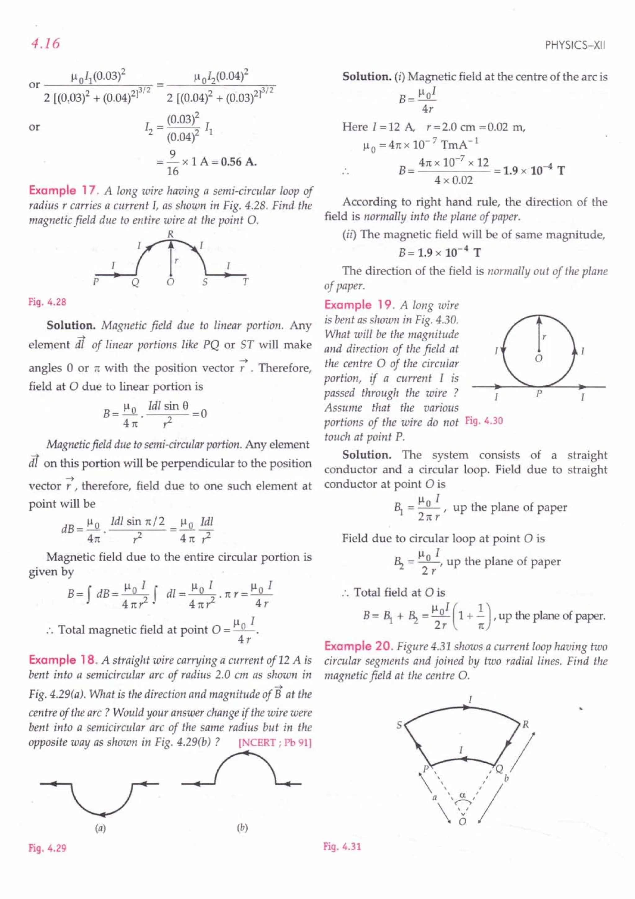
![MAGNETIC EFFECT OF CURRENT
Solution. Since the point 0 lies on lines SP and QR,
so the magnetic field at 0 due to these straight portions
is zero.
The magnetic field at 0 due to the circular segment
PQ is
Here, I = length of arc PQ = ex a
.. 1 = ~o ~,directed normally upward
4n a
Similarly, the magnetic field at 0 due to the circular
segment SR is
~ = ~0 .!...:!.., directed normally downward.
4n b
The resultant field at 0 is
B = 1 _ ~ = ~o I ex [!_!]
4n a b
B = ~ 0 I ex (b - a) .
4nab
or
Example 21 . The wire shown in Fig. 4.32 carries a current
of 10 A. Determine the magnitude of the magnetic field at the
centre O. Given radius of the bent coil is 3 em.
[Punjab 01 ; AIIMS 13)
Fig. 4.32
Solution. As e (rad) = ~
Radius
3n =!.. or I = 3nr
2 r 2
According to Biot-Savart law, magnetic field at the
centre 0 is
B_~oIl_~o 13nr_~o3nI
- 4n ,z - 4n . ,z . 2 -4n 2" -;
4n x 10- 7 3 22 10
----- -x----;:;-
4n 2 . 7 3 x 10-2
= 1.57 x 10⁻³ T.
Example 22. In Fig. 4.33, abed is a circular coil of
non-insulated thin uniform conductor. Conductors pa and
qc are very long straight parallel conductors tangential to
the coil at the points a and c. If a current of 5A enters the coil
from p to a,find the magnetic induction at 0, the centre of
the coil. The diameter of the coil is 10 em.
4.17
SA
--~~----~~-----p
b
SA
d
--~~-----~------q
Fig. 4.33
Solution. Here Iabc = lade =2.5 A,
r = Oa = Ob = Oc = Od = 5 em = 5 x 10- 2 m.
The magnetic induction at 0 due to the current in
part abc of the coil is equal and opposite to the
magnetic induction due to the current in part adc. So
magnetic induction at 0 due to the coil is zero.
Magnetic induction at 0 due to the straight conduc-
tor pa (a half infinite segment) is
1 =..!. ~o I = 4nx.1O-
7
x 5 =1O-5T,
22nr 4nx5x10-2
normally out of the plane of paper.
Similarly, magnetic induction at 0 due to straight
conductor qc is ~
~ = ~o I =1O-5T,
4nr
normally out of the plane of paper.
Total magnetic induction at 0 is
B= 1 + ~ =10-5 + 10-5 =2 x 10⁻⁵
T,
normally out of the plane of paper.
Example 23. The current-loop PQRSTP formed by two
circular segments of radii R} and Rz carries a current of I
ampere. Find the magnetic field at the common centre O.
What will be thefield if angle ex = 90° ?
Solution. The magnetic field at 0 due to each of the
straight parts PQ and RS is zero because e = 0°, for each
of them.
T
Fig. 4.34
Magnetic field at the centre 0 due to circular segment
QR of radius Rz is
R = ~o ~ I
'1 4n' ~ 2](https://image.slidesharecdn.com/slaroraclass12thphysicsbyrockytrickster-250318042948-c8b51a5a/75/SL-ARORA-CLASS-12TH-PHYSICS-BY-ROCKY-TRICKSTER-pdf-342-2048.jpg)
![4.18
Here,
12 = length of circular segment QR = a Rz
~ = Il 0 .!.5:.. , directed normally downward
41t Rz
Similarly, the magnetic field at 0 due to the circular
segment STP is
Il I (21t- a) .
.~ =~ ,dIrected normally downward
41t Rl
Hence the resultant field at 0 is
B= ~ + ~ =lloI(~+ 21t-a],
41t Rz Rl
directed normally downward
If a = 90° = 1t/2, then
B-!:JL!. (_1t +~] = lloI [~ +~]
- 41t 2 Rz 2 Rl 8 R2 Rl .
Example 24. A current 1=5.0 A flows along a thin wire
shaped as shown in Fig. 4.35. The radius of the curved part
of the wire is equal to R = 120 mm, the angle 2 ~ = 90°. Find
the magnetic induction of the field at the point O.
A
o
A
,~,R
, ' '2«jl = 900- , ,
, ,
B
Fig. 4.35
Solution. Magnetic induction at 0 due to the line
segment AB is
~=Ilox I [sin c i-sin e]
41t R cos ~
= Il 0 . '!:..!.. tan ~ , acting normally downwards
41t R
Magnetic field at 0 due to the current through arc
segment is
~ = Ilo x i (2n -2~), acting normally downwards
4n R
Total magnetic induction at 0,
Ilo I
B= ~ + ~ = 2n . R [n - ~+ tan ~]
4n x 10-
7
x 5 [n nJ
= 2nxO.120
n
-4+tan
4
2 x 10-
7
x 5 x 3.356 = 2.8 x 10⁻⁵ T.
0.120
PHYSICS-XII
Example 25. Two wires A and B have the same length
equal to 44 em and carry a current of 10 A each. Wire A is
bent into a circle and wire B into a square. (a) Which wire
produces a greater magnetic field at the centre? (b) Obtain
the magnitudes of the fields at the centres of the two wires.
Solution. Given I =10 A,
Length of each wire = 44 cm = 4L (say)
(a) Suppose the wire is bent into a circle of radius R.
Then its perimeter 21t R = 4 L
:. Magnetic field at the centre of the circular wire is
B
_llo I _Ilo I1t_Ilo I1t
--------- ...(1)
2R 2nR 4L
Now suppose the wire B is bent into a square of
side L. We know that the magnetic field due to a wire
of finite length whose ends make angles a and 13
with
the perpendicular dropped on wire from the given
point at distance r from it is given by
dB= Ilo I (sin a + sin 13)
4nr
r , 0
, ,
, ,
, ,
,
" L
, ,
, ,
2
"
L -------
L
(/" ,
, ,
,
, ,
, ,
, ,,
C
Fig. 4.36
:. Magnetic field at 0 due to conductor AB is
dB= Ilo I (sin 450 + sin 450) = 2.J2 Ilo I
4n. L/2 4nL
[.: a=I3=45°,r=L/2]
By symmetry, magnetic field at 0 due to all the
four sides of the square will be in the same direction.
Hence total field at 0 due to the current-carrying
square is
B= 4 x 2.J2 lloI = S.J2lloI
41tL 4nL
...(2)
Comparing equations (1) and (2), we find that the
square wire produces a greater field at its centre.
(b) Magnetic field at the centre of the circular wire is
B= lloIn = 4nx10-
7
x10x n T
4L 44 x 10-2
= 0.9 x 10--4 T [": 4L=44cm]](https://image.slidesharecdn.com/slaroraclass12thphysicsbyrockytrickster-250318042948-c8b51a5a/75/SL-ARORA-CLASS-12TH-PHYSICS-BY-ROCKY-TRICKSTER-pdf-343-2048.jpg)
![MAGNETIC EFFECT OF CURRENT
Magnetic field at the centre of the square wire is
B= 8$ x 1-101 = 8 x 1.414 x 4n x 10 -7 x 10 T
41t L n x 44 x 10-2
::.1.0 x 10-4 T.
Example 26. A straight wire, of length ~ metre, is bent
2
into a circular shape. If the wire were to carry a current of
5 A calculate the magnetic field, due to it, before bending, at
a point distant 0.01 times the radius of the circleformed from
it. Also calculate the magnetic field, at the centre of the
circular loopformed, for the same value of current.
[CBSE OD 04C]
Solution. Here 2nr = ~ metre
2
1
r=- =0.25 m
4
Magnetic field due to straight wire,
B=l-Io1= ~01 4nxlO-
7
x5
2nr 2n x 0.01 r 2n x 0.01 x 0.25
= 4 x 10⁻⁴
T
Magnetic field at the centre of the circular loop,
B= 1-10
1 = 4n x 10-
7
x 5 = 1.256 x 10⁻⁵ T.
2r 2 x 0.25
<prOblems for Practice
1. Consider a tightlywound 100turn coilofradius 10em,
carrying a current of 1 A. What is the magnitude of
the magnetic field at the centre of the coil ?
[NCERTI (Ans. 6.28 x 10⁻⁴
1)
2. A circular loop of one turn carries a current of 5.0A.
If the magnetic field at the centre is 0.20 mT, find
the radius of the loop. (Ans. 1.57 cm)
3. What current has to be maintained in a circular coil
of wire of 50 turns and 2.54 ern in radius in order to
just cancel the effect of earth's magnetic field at a
place where the horizontal component of earth's
field is 1.86 x 10⁻⁵ T ? (Ans. 0.015A)
4. A semicircular arc of radius 20 em carries a current
of 10 A. Calculate the magnitude of the magnetic
field at the centre of the arc. [CBSE D 021
(Ans. 1.57 x 10-51)
5. An alpha particle moves along a circular path of
radius 1.0x10⁻¹⁰
m with a uniform speed of
2 x10⁶
ms-1. Calculate the magnetic field produced
at the centre of orbit. (Ans. 13.4T)
6. The electron in hydrogen atom moves around the
proton with a speed of 2.2x10⁶
ms-1 in a circular
orbit of 5.3x10⁻¹¹
m. Calculate (i) the equivalent
4.19
current (ii) equivalent dipole moment and (iii) the
magnetic field at the site of the proton.
[Ans. (i) 1.057x 10⁻³
A (ii) 9.32 x 10⁻²⁴
Am-2
(iii) 12.5 T]
7. A circular coil has 35 turns and a mean radius of
4.0 cm. It carries a current of 1.2 A. Find the
magnetic field (i) at a point on the axis of the coil at a
distance of 40 em from its centre and (ii) at the centre
of the coil. [Ans. (i) 6.5 x 10⁻⁷
T (ii) 6.6 x 10⁻⁴
T]
8. A thick straight copper wire, carrying a current of
10 A is bent into a semicircular arc of radius 7.0 em
as shown in Big. 4.37(a). (i) State the direction and
calculate the magnitude of magnetic field at the
centre of arc. (ii) How would your answer change if
the same wire were bent into a semicircular arc of
the same radius but in opposite way as shown in
Fig. 4.37(b) ? [CBSE Sample Paper 981
[Ans. (i) 4.5 x 10⁻⁵
T, outside the plene of paper,
(ii) 4.5 x1O-5
T,into the plane of paper]
(a) (b)
Fig. 4.37
9. A long wire is bent as shown in Fig. 4.38. Find the
magnitude and direction of the magnetic field at
the centre a of the circular part, if a current I is
passed through the wire.
[Ans. ~ (1--.!) normally into
2 R n
the plane of paper]
Fig. 4.38 Fig. 4.39
10. Figure 4.39 shows two semicircular loops of radii
~ and Rz carrying current I. Find the magnitude
and direction of the magnetic field at the common
centre O.
[Ans. ~o I (2.+ 2.J,normally downward]
4 ~ Rz](https://image.slidesharecdn.com/slaroraclass12thphysicsbyrockytrickster-250318042948-c8b51a5a/75/SL-ARORA-CLASS-12TH-PHYSICS-BY-ROCKY-TRICKSTER-pdf-344-2048.jpg)
![4.20
11. A circular segment of radius 10 ern subtends an
angle of 60° at its centre. A current of 9 A is flowing
through it. Find the magnitude and direction of the
magnetic field produced at the centre (Fig. 4.40).
(Ans. 9.42 x 10⁻⁶ T)
Fig. 4.40 Fig. 4.41
12. A current of I ampere is flowing through the bent
wire shown in Fig. 4.41. Find the magnitude and
direction of the magnetic field at point O.
(
Ans. B= !:Jl. !..5:. , directed normally downward)
411: r
13. In Fig. 4.42, the curved portion is a semi-circle and
the straight wires are long. Find the magnetic field
at the point O. [Ans. Il;/ (1+;)]
r
d
_+---1
'0
Fig. 4.42
14. Two identical coils each of radius R and having
number of turns N are lying in perpendicular
planes, such that they have common centre. Find
the magnetic field at the centre of the coils, if they
carry currents equal to I and -!3I respectively.
(Ans. Il0 NI/ R)
15. A metallic wire is bent
into the shape shown
in Fig. 4.43 and carries
a current I. If ais the
common centre of all
the three circular arcs
of radii r, 2r and 3r,
find the magnetic
field at the point 0.
[
Ans. 51loI 8, 1
24nr
normally inward
0,
8 r_
I
,
, r
-
Fig. 4.43
PHYSICS-XII
HINTS
1. As the coil is tightly wound, so radius of each turn,
r=10cm =O.lm
B= lloNI = 411:
x 10-7
x100xl
2r 2xO.l
= 211:
x 10-4 = 6.28 x10⁻⁴
T.
2. Radius r = IloNI = 411:
x 10-
7
x 1x5.0
, 2B 2xO.20xl0 3
= 1.57 x10⁻²m ;= 1.57 em.
OT Ilo NI = B
3. B=BH 2r H
41tx 10-
7
x50xI = 1.86 x 10⁻⁵
2 x 2.54 x 10 2
1.86 x 2 x 2.54
I = = 0.015 A.
411:
x 50
or
4. Use B= lloI .
4r
5. Take charge on a-particle = + 2e and proceed as in
Example 12 on page 4.14.
21tr
6. (i) Period of revolution, T = -
v
Equivalent current, I = !.. = ~
T 211:r
1.6 x 10-19 x 2.2 x 106 -3
= 2x3.14x5.3xlO 11 =1.057x10 A
(ii) Equivalent dipole moment,
m=IA=Ix11:r2
= 1.057 x 10-3 x3.14x(5.3xl0-11)2
= 9.32 x 10⁻²⁴
Am2.
.. Il0 I 411:
x 10-7
x 1.057 x 10-3
(Ill) B = -- = 11 = 12.5 T.
2r 2 x 5.3 x 10
7. (i) N = 35, I = 1.2 A, a = 4.0em = 0.04 m,
r = 40 em = 0.40 m
B _ Il0 NJa
2
411:
x 10-7 x 35 x 1.2 x(0.04)2
axial - 2 (a2 + r2)3/2 2 [(0.04)2 + (0.40)2]3/2
4 x 3.14 x 10-7
x 35 x 1.2 x 0.0016
2 x 0.1616 x 0.402
= 6.5 x 10⁻⁷
T.
(ii) Bcentre
= Il~NI= 6.6 x 10⁻⁴ T.
8. (i) Magnetic field at the centre of the arc is
B= Ilo I
4r
Here J = 10 A, r = 7 em = 0.07 m,
Il0 = 411:
x 10-7
TmA -1](https://image.slidesharecdn.com/slaroraclass12thphysicsbyrockytrickster-250318042948-c8b51a5a/75/SL-ARORA-CLASS-12TH-PHYSICS-BY-ROCKY-TRICKSTER-pdf-345-2048.jpg)
![MAGNETIC EFFECT OF CURRENT
41txlO-7xlO 5
B= = 4.5 x 10- T.
4 x 0.07
The direction of the field is normally outside the
plane of paper.
(ii) B = 4.5 x 10-
4
T. The field Bwill point normally
into the plane of paper.
9. Magnitude of the magnetic field at 0 due to the
straight part of the wire is
Il I
~ =.......Q..
-, normally out of the plane of paper
2n R
Magnetic field at the centre 0 due to the current
loop of radius R is
Ilo 1 .
~ = --, normally mto the plane of paper
2R
Resultant field at 0 is
normally into the plane of paper.
10. B= ~ + ~ =~oI + 1101 =1l01 (~+~J.
4~ 4~ 4 Rl R2
11. Here 8= 60° = ~ rad
3
1 1t 1=!:!.
As 8(rad) =- .. or
r 3 r 3
4.21
Magnetic field at adue to the upper straight wire is
1 1101 lloI
~ = 2: x 21t (d /2) = 21td
Similarly, field at a due to lower straight wire is
Ilo I
~ = 2nd
Field at 0 due to the semicircle of radius d /2 is
_ 1 Ilo I _ Ilo I
~-2:x2(d/2)- 2d
Resultant field at 0,
B=~+~+~=lloI[l+~].
2d 1t
14. Magnetic fields produced by the two coils at their
common centre are
~ = lloN1 and ~ = lloN ..J31
2R 2R
The planes of the two coils are perpendicular to
each other. So the fields ~ and ~ will also be
perpendicular to each other, as shown in Fig. 4.44.
B2 - - - - - - - - - - - B
According to Biot-Savart law, magnetic field at the F'
19.4.44
centre a is
10-
7
x 3.14 x 9 = 9.42 x10⁻⁶ T.
3 x 0.10
-+
12. Any element dl on the arc will be perpendicular to
the position vector J7,so the field due to one such
element at the centre 0 will be
dB = ~ 0 Idl sin 1t/2 = Il 0 Idl
4n r2 41t . r2
Magnetic field due to the entire arc at the centre 0,
B=f dB= 1101 f dl= 1101 .1
41tr2 4nr2
But 1= length of arc = or
B= lloI .ar=~oIa
.. 41t,2 4n r
13. Magnetic field at point a due to any current element
is perpendicular to and points out of the plane of
paper.
The resultant field at the common centre is
B=~~2+ B}
= [ ("~~Ir+ (~ ~~ NIrr
= lloNI (1+ 3)1/2 = lloNI.
2R R
15. Magnetic field at 0 due to the straight parts of the
wire will be zero. Magnetic fields at 0 due to the
three circular arcs of radii r, 2r and 3r are '
R __ 1-101 ~
'"1 acting normally inward
41t . r '
1101 8
~ = - - acting normally outward
41t . 2r '
lloI 8
~ = - - acting normally inward
41t . 3r '
Thus the total magnetic field at the centre 0 is
B = ~ _ ~ + ~ = ~ oI (~ _ ~ + ~)
41t r 2r 3r
51l I
= _0_ 8f acting normally inward.
241tr](https://image.slidesharecdn.com/slaroraclass12thphysicsbyrockytrickster-250318042948-c8b51a5a/75/SL-ARORA-CLASS-12TH-PHYSICS-BY-ROCKY-TRICKSTER-pdf-346-2048.jpg)
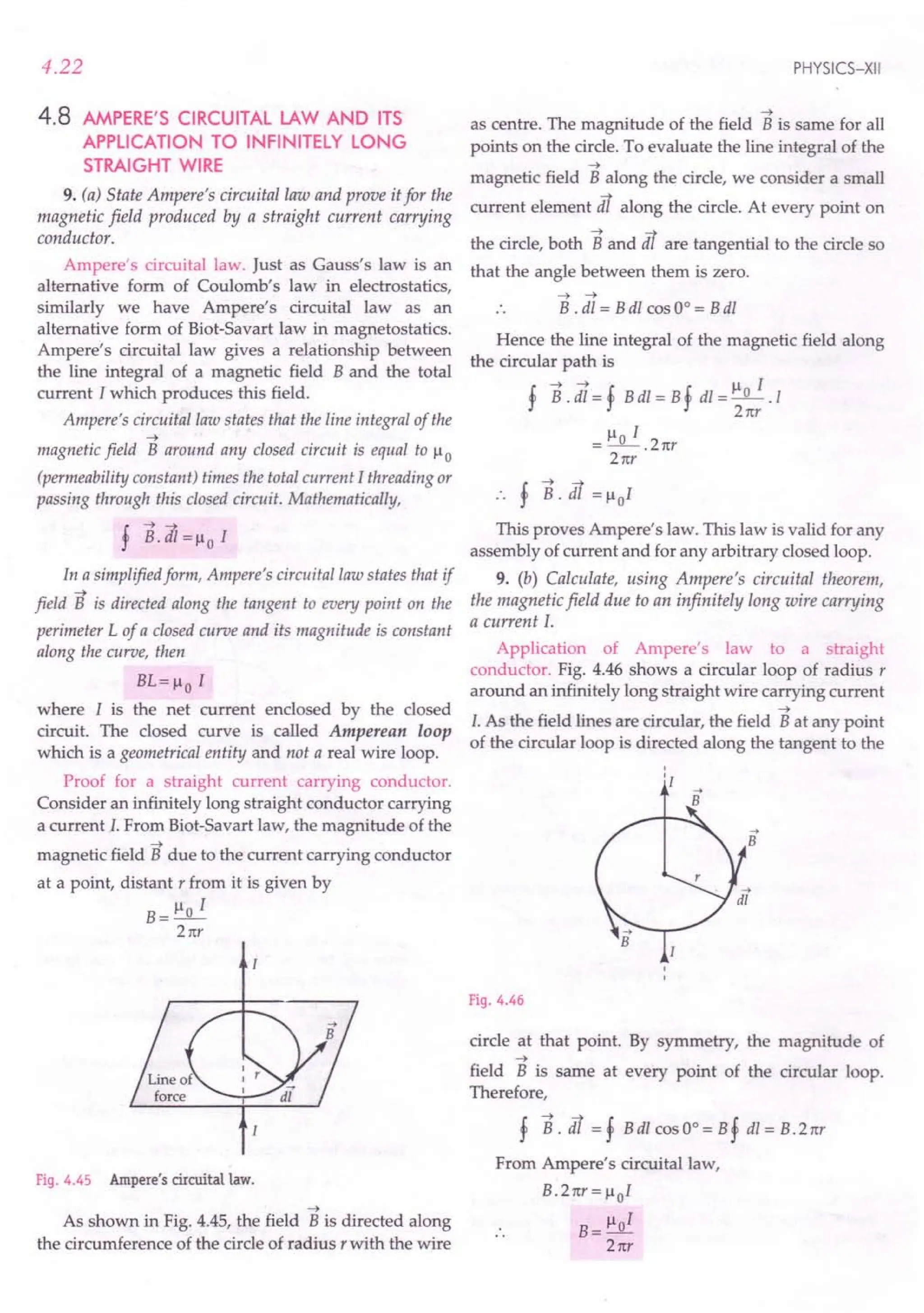
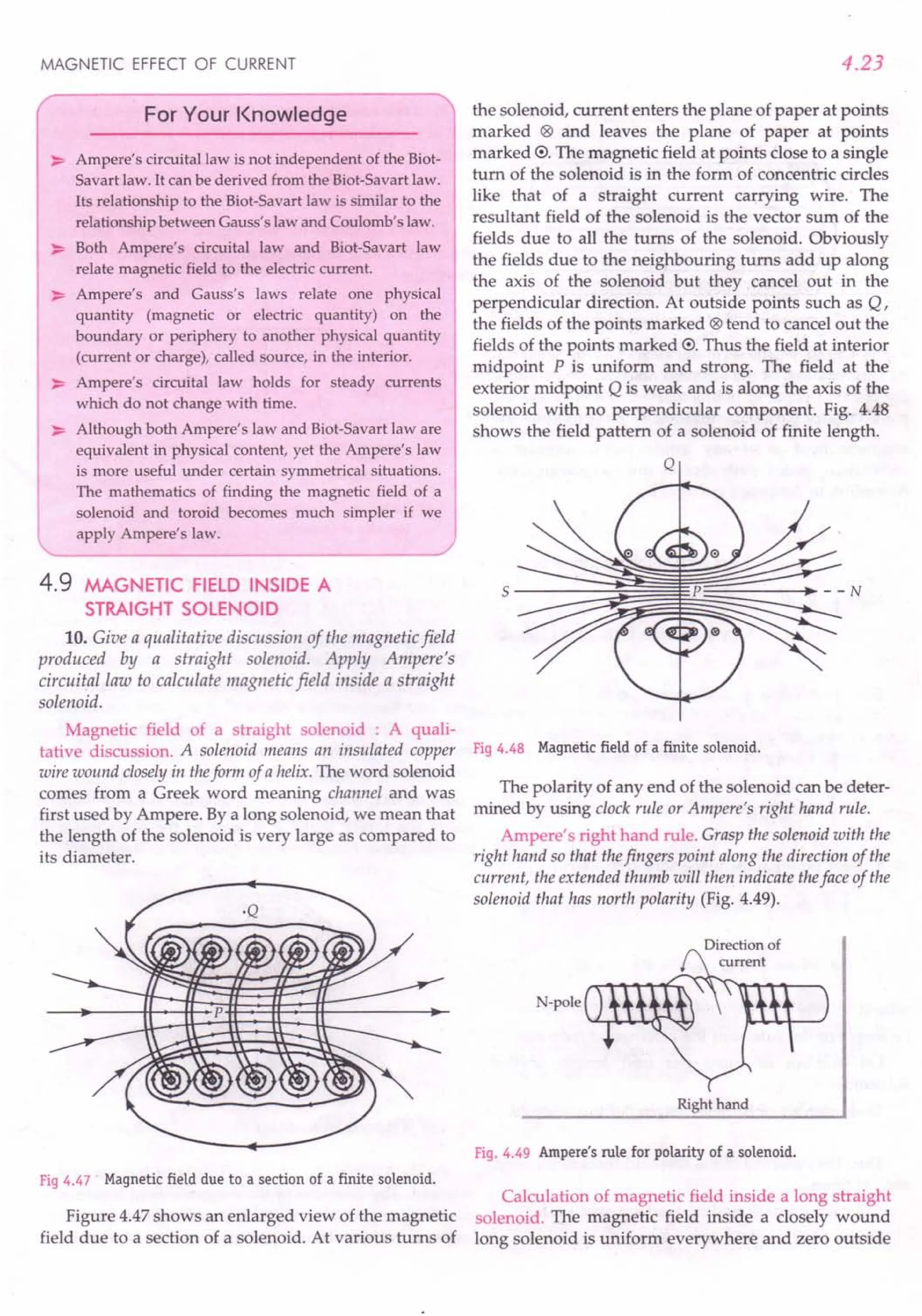
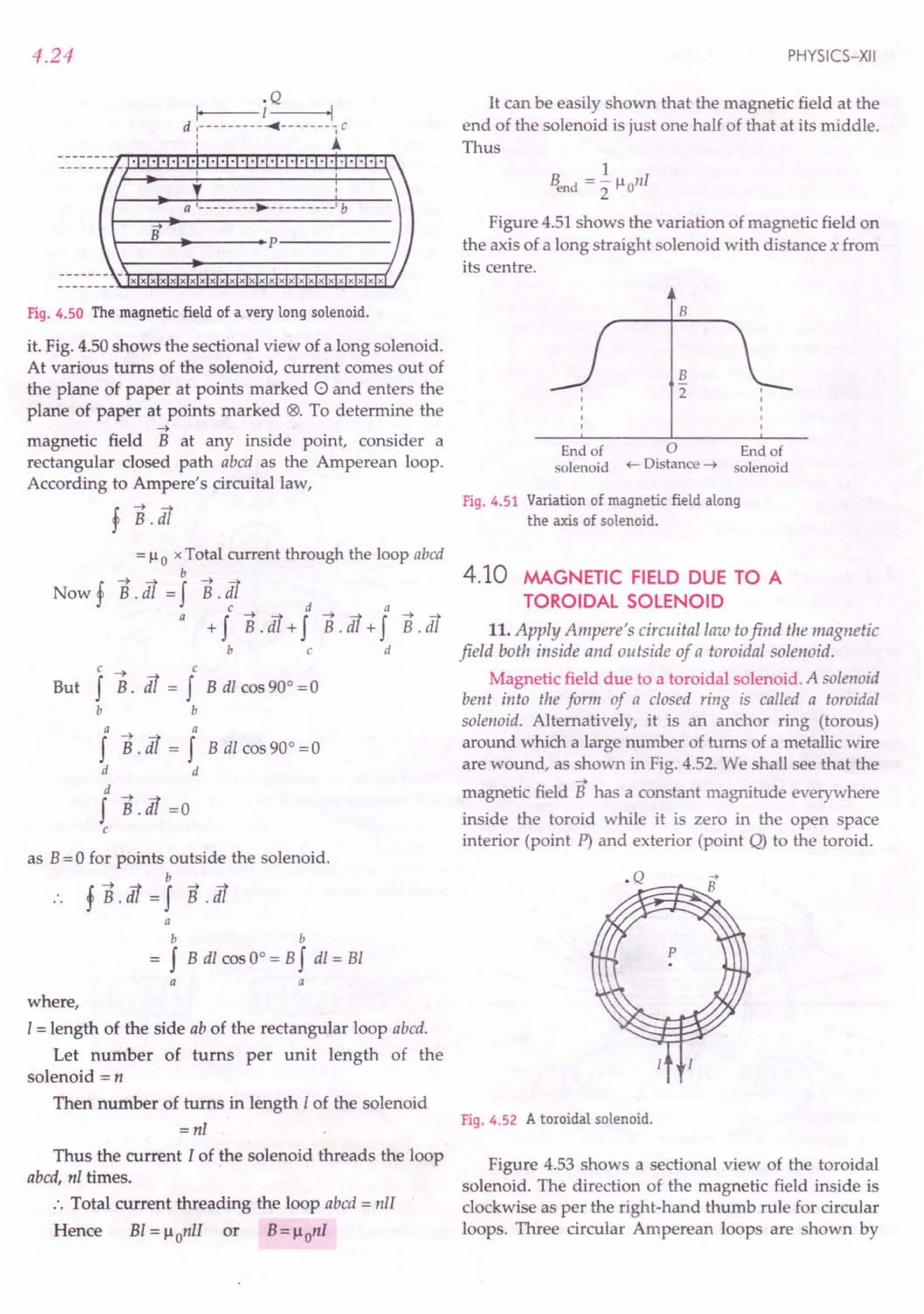
![MAGNETIC EFFECT OF CURRENT
Fig. 4.53 A sectional view of the toroidal solenoid.
dashed lines. By symmetry, the magnetic field should
be tangential to them and constant in magnitude for
each of the loops.
1. For points in the open space interior to the
toroid. Let ~ be the magnitude of the magnetic field
along the Amperean loop 1of radius r1
.
Length of the loop 1, ~ = 2 n 1J
As the loop encloses no current, so I = 0
Applying Ampere's circuital law,
~ ~ = ~o I
or ~ x 2 n r1 = ~0 x 0
or ~ =0
Thus the magnetic field at any point P in the open space
interior to the toroid is zero.
2. For points inside the toroid. Let B be the
magnitude of the magnetic field along the Amperean
loop 2 of radius r.
Length of loop 2, ~ = 2 nr
If N is the total number of turns in the toroid and I
the current in the toroid, then total current enclosed by
the loop 2 = NI
Applying Ampere's circuital law,
B x 2 nr = ~ 0 x NI
or B= ~o NI
2 nr
If r be the average radius of the toroid and n the
number of turns per unit length, then
N=2nrn
B= ~o nl
3. For points in the open space exterior to the
toroid. Each turn of the toroid passes twice through the
area enclosed by the Amperean loop 3. But for each
turn, the current coming out of the plane of paper is
cancelled by the current going into the plane of paper.
Thus, I = 0 and hence ~ = o.
4.25
For Your Knowledge
~ The magnetic field inside a toroidal solenoid is
independent of its radius and depends only on the
current and the number of turns per unit length. The
field inside the toroid has constant magnitude and
tangential direction at every point.
~ In ideal toroid, the coils are circular and magnetic
field is zero external to the toroid. In a real toroid, the
turns form a helix and there is a small magnetic field
external to the toroid.
~ Toroids are expected to playa key role in the Tokamak
which acts as a magnetic container for the fusion of
plasma in fusion (thermonuclear) power reactors.
Formulae Used
! --->--->
1. Ampere's circuital law, r B dl = ~oI
When B is directed along tangent to every point
on closed curve L, BL = ~ 0 I
2. Magnetic field due to straight solenoid,
(i) At a point well inside the solenoid, B = ~0 nI
(ii) At either end of the solenoid, Bend = ~ ~o nI
Here n is the number of turns per unit length.
3. Magnetic field inside a toroidal solenoid, B = ~ 0 nI
Magnetic field is zero outside the toroid.
Units Used
B is in tesla, current I in ampere and n in m -1.
Example 27. A solenoid coil of 300 turnslm is carrying a
current of 5 A. The length of the solenoid is 0.5 m and has a
radius of 1 em. Find the magnitude of the magnetic field
inside the solenoid. [CBSE F 04]
Solution. Here n = 300 tums/m, 1=5 A
B= ~ onI = 4n x 10-7
x 300 x 5 = 1.9 x 10⁻³
T.
Example 28. A solenoid of length 0.5 m has a radius ofl em
and is made up of 500 turns. It carries a current of 5 A. What
is the magnitude of the magnetic field inside the solenoid?
[NCERT]
Solution. Number of turns per unit length,
N 500
n =- =-- =1000 turns/m
I 0.5 m
Here 1=0.5 m and r =0.01 m i.e., I» a. So we can
use formula for magnetic field inside a long solenoid.
B= ~onI = 4n x 10-7
x 1000 x 5 = 6.28 x 10⁻³
T.](https://image.slidesharecdn.com/slaroraclass12thphysicsbyrockytrickster-250318042948-c8b51a5a/75/SL-ARORA-CLASS-12TH-PHYSICS-BY-ROCKY-TRICKSTER-pdf-350-2048.jpg)
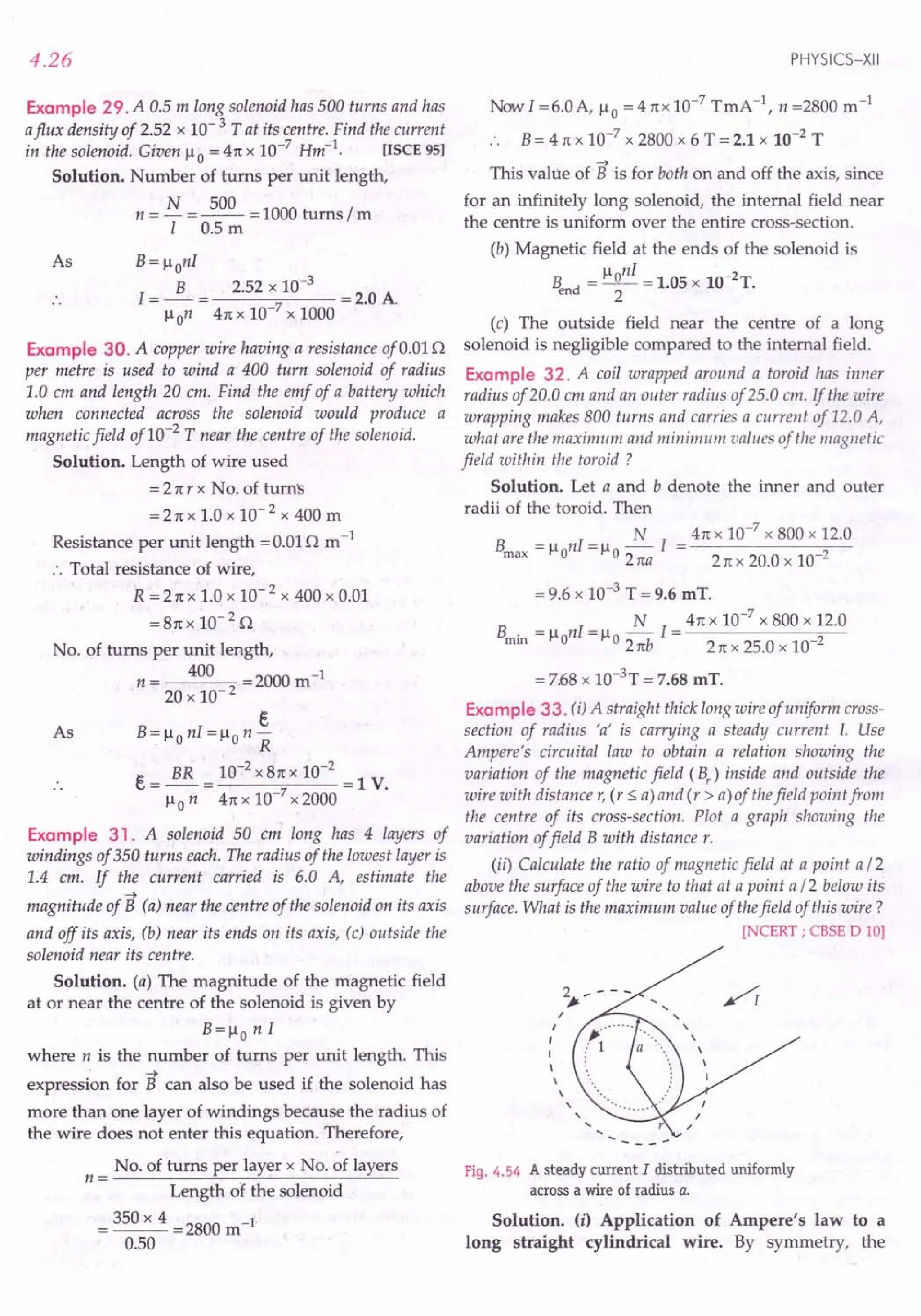
![MAGNETIC EFFECT OF CURRENT
magnetic lines of force will be circles, with their centres
on the axis of the cylinder and in planes perpendicular
to the axis of the cylinder. So we consider Amperean
loop as a circle of radius r.
Field at outside points. The Amperean loop is a
circle labelled 2 having radius r > a.
Length of the loop, L=21tr
Net current enclosed by the loop = I
By Ampere's circuital law,
BL=1l01
Bx2rrr=1l01
B = 1101
21tr
or
or [For r > a]
i.e.,
1
Boc-
r
[For outside points]
Field at inside points. The Amperean loop is a circle
labelled 1with r < a.
Length of the loop, L = 21tr
Clearly, the current enclosed by loop 1is less than I.
As the current distribution is uniform, the fraction of I
enclosed is
l' = _1_x 1t? = I?
1ta2 a2
Applying Ampere's law,
BL=llo I'
I?
or B x 2 ttr = 110 2
a
or [For r < a]
i.e., [For inside points]
Bocr
Thus the field B is proportional to r as we move
from the axis of the cylinder towards its surface and
then it decreases as! . The variation of B with distance r
r
from the centre of the wire is shown in Fig. 4.55(a).
B
L-----------------~r
(a) (b)
Fig. 4.55 (a) Sketch of the magnitude of the magnetic field for
the long conductor of radius a.
4.27
(ii) Suppose the point P lies at distance a / 2 above
the surface of the wire and point Q lies at distance a / 2
below the surface. [Fig. 4.55(b)]
Magnetic field at point P at distance r = 3a /2 from
the axis of the wire is
_ 1101_ 1101 _ 1101
Bp - 21tr - 2 rt{3/2) a - 3rta
Magnetic field at point Q at distance r = a /2 from
the axis of the wire is
R..= 1l0Ir = 1101 (~) = 1101
.! 2 rta2 2 rta2 2 4rta
Bp 1101 41ta
-=-x-=4:3.
It? 3rta 1101
Clearly, B is maximum on the surface of the wire
i.e., at r = a. Hence,
B = 1101
max 2rta
Example 34. A wire of radius 0.5 em carries a current of
100 A, which is uniformly distributed over its cross-section.
Find the magnetic field (j) at 0.1 em from the axis of the wire,
(ii) at the surface of the wire and (iii) at a point outside the
wire 0.2 em from the surface of the wire.
Solution. Here R = 0.5 em = 0.5 x 10⁻²
m, I = 100 A
We use the results of the above example.
(i) B -~ r
inside - 21tR2 .
41tx 10-7
x 100 x 0.1 x 10-2
21t x (0.5 x 1O-2l
= 8.0 x 10⁻⁴ T.
(ii) B = 1101 = 41tx 10-
7
x 100
surface 21tR 21t x 0.5 x 10-2
= 4.0 x 10⁻³ T.
(iii) Here r =0.5 + 0.2 =0.7 em =0.7 x 10⁻²
m
B = 1101 = 41tx 10-
7
x 100
outside 2 nr 21t x 0.7 x 10-2
a
= 2.86 x 10-sT.
rproblems For Practice
1. A long solenoid consists of 20 turns per em. What
current is necessary to produce a magnetic field of
20 mT inside the solenoid? . (Ans. 8.0 A)
2. A long solenoid is made by closely winding a wire
of radius 0.5 mm over a cylindrical non-magnetic
frame so that successive turns nearly touch each
other. What will be the magnetic field at the centre
of the solenoid if a current of 5 A flows through it ?
(Ans. 21tx 10-3 T)](https://image.slidesharecdn.com/slaroraclass12thphysicsbyrockytrickster-250318042948-c8b51a5a/75/SL-ARORA-CLASS-12TH-PHYSICS-BY-ROCKY-TRICKSTER-pdf-352-2048.jpg)
![4.28
3. The magnetic field at the centre of a 50 em long
solenoid is 4.0 x 10⁻²
T when a current of 8.0 A
flows through it. What is the number of turns in the
solenoid? Take rt = 3.14. (Ans. 1990)
4. A solenoid is 1.0 m long and 3.0 em in diameter. It
has five layers of windings of 850 turns each and
carries a current of 5.0 A. (i) What is B at its centre?
(ii) What is the magnetic flux CPB for a cross-section
of the solenoid at the centre?
[Ans. (i) 2.67 x 10⁻²
T, (ii) 1.9 x 10⁻⁵
Wb]
5. A solenoid is 2.0m long and 3.0em in diameter. It has
5 layers of winding of 1000turns each and carries a
current of 5.0 A. What is the magnetic field at the
centre? Use the standard value of Ii o [Punjab 97C]
(Ans. 1.57x1O-2
T)
6. A toroid has a core of inner radius 20 em and outer
radius 22 em around which 4200 turns of a wire are
wound. If the current in the wire is 10 A, what is the
magnetic field (i) inside the core of toroid (ii) outside
the toroid and (iii) in the empty space surrounded
by the toroid. [Ans. (i) 0.04 T (ii) Zero (iii) Zero]
7. A long straight solid conductor of radius 4 em
carries a current of 2 A, which is uniformly distri-
buted over its circular cross-section. Find the
magnetic field at adistance of 3 em from the axis of
the conductor. (Ans.7.5 x 10- 6 T)
HINTS
1. Here n= 20cm-1
= 20 x 102
m",
B = 20 mT = 20 x 10- 3 T
B 20 x 10-3
Current, I = - = 7 2 = B.OA.
Ii on 41tx 10- x 20 x 10
2. Diameter of the wire = 2 x 0.5 = 1.0mm = 10-3
m
.. Number of turns per unit length,
1 103-1
n= 10-3 m = m
Also, I = 5 A, lio = 41tx 10-7 Tm A-1
B = lio nI = 4n:x 10-7
x103
x5 = 21tx 10-3
T.
N
3. B = Ii onI = Ii 0 1I
BI 4.0 x 10-2
x 0.50
N=-= =1990.
lioI 4 x 3.14 x 10-7
x 8
4. umber of turns per unit length,
5 x 850 -1
11= --- = 4250 m
1.0
(I) B = Ii 0 nI = 4n:x 10-7
x 4250 x 5.0= 2.67 x10⁻²
T.
(ii) CPB = BA = B xm2
= 2.67 x 10-2 x3.14x(1.5 x 10-2)2
= 1.9 x10⁻⁵
Wb.
PHYSICS-XII
5. Number of turns per unit length,
/! = 5 x 1000 = 2500m-1
2.0
B= Ii onI = 41tx 10-7
x 2500x5.0 = 1.57 x 10⁻²
T.
6. Mean radius of toroid,
20+ 22
r = --- = 21em = 0.21m
2
umber of turns per unit length
4200 _42_0_0_= _10_0_0
m-1
Zrr r 21tx 0.21 rt
(i) Field inside the core of the toroid,
-7 1000
B = lionl = 41tx10 x -- x 10 = 0.04T.
n:
(ii) Magnetic field outside the toroid is zero.
(iii) Magnetic field in the empty space surrounded
by toroid is zero.
7. Current enclosed by the loop of radius r,
, T 2 Ir
2
1=-2 x nr =-2
n:R R
Using Ampere's circuital law,
BL= lio!'
Ir
2
B __liolr
B x Znr = Ii 0 -2 or 2
R 21tR
41tx 10-7
x2 x3 x 10-2
-6
------;2...,,-2 - = 7.5 x 10 T.
21tX (4 x 10- )
4.11 FORCE ON A MOVING CHARGE
IN A MAGNETIC FIELD
12. State the factors on which the force acting on a
charge moving in a magnetic field depends. Write the
expression for this force. When is this force minimum and
maximum? Define magnetic field. Also define the Sf unit
of magnetic field.
Magnetic force on a moving charge. The electric
charges moving in a magnetic field experience aforce, while
there is no such force on static charges. This fact was
first recognized by Hendrik Antoon Lorentz, a great
Dutch physicist, nearly a century ago.
~
Suppose a positive charge q moves with velocity v
~ ~ ~
in a magnetic field B and v makes an angle e with B,
as shown in Fig. 4.56. It is found from experiments that
~
the charge q moving in the magnetic field B expe-
~
riences a force F such that
1. the force is proportional to the magnitude of the
magnetic field, i.e., F ex: B
2. theforce is proportional to the charge q, i.e., F ex: q
3. theJorceis proportionalto the component of the velocity
v in the perpendicular direction of thefield B, i.e.,
F ex: v sin e](https://image.slidesharecdn.com/slaroraclass12thphysicsbyrockytrickster-250318042948-c8b51a5a/75/SL-ARORA-CLASS-12TH-PHYSICS-BY-ROCKY-TRICKSTER-pdf-353-2048.jpg)
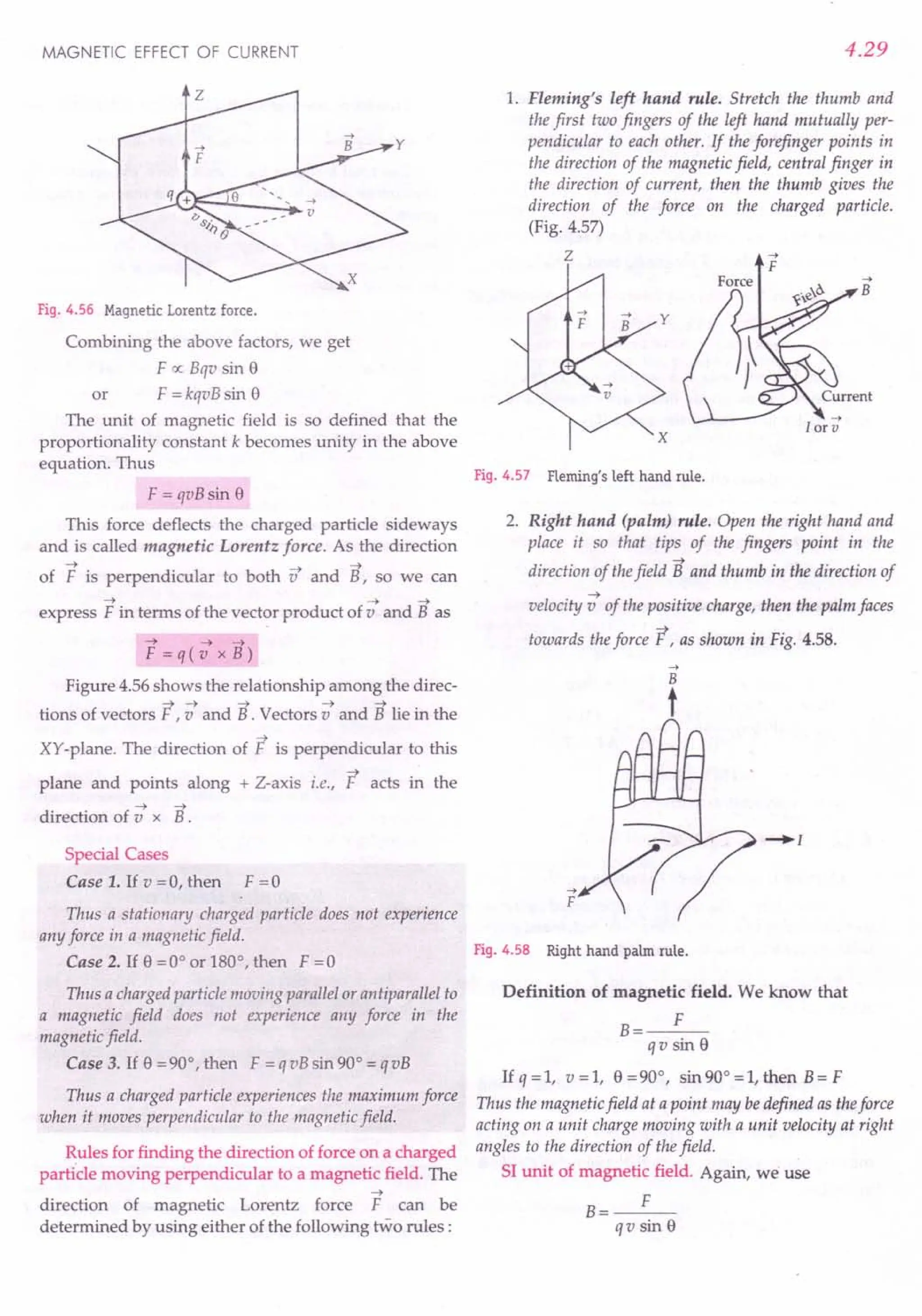
![4.30
IfF=lN, q=lC, v=lms-
1
, 9=90°,then
Sl unit of B.e IN
1 C.1 ms-1
. sin 90°
IN
1A.1m
= 1 N A -1 m -1 = 1 tesla.
Thus the 51 unit of magnetic field is tesla (T).
One tesla is that magnetic field in which a charge of
1 C moving with a velocity of 1ms -1 at right angles to
the field experiences a force of one newton.
A field of one tesla is a very strong magnetic field.
Very often the magnetic fields are expressed in terms
of a smaller unit, called the gauss (G).
1 gauss = 10 -4tesla
Table 4.1 Some Typical Magnetic Fields
108
T
IT
10-2
T
10-4 T
1O-12
T
Surface of a neutron star
Large field in the laboratory
Field near a bar magnet
Field on the earth's surface
Field in interstellar space
Dimensions of magnetic field. Clearly,
MLr2
[B] = [F]
[q][v][sin 9]
= [Mr2A-1].
AT.Lr1
.1
Here A represents current.
4.12 LORENTZ FORCE
13. What is Lorentz force? Write an expression for it.
Lorentz force. The total force experienced by a charged
particle moving in a region where both electric and magnetic
fields are present, is called Lorentz force.
A charge q in an electric field E experiences the
electric force,
-t
This force acts in the direction of field E and is
independent of the velocity of the charge.
The magnetic force experienced by the charge q
-t -t
moving with velocity v in the magnetic field B is
given by
PHYSICS-XII
-t
This force acts perpendicular to the plane of v and
-t -t
B and depends on the velocity v of the charge.
The total force, or the Lorentz force, experienced by
the charge q due to both electric and magnetic field is
given by
-t -t -;::t
F =Fe+F nt
or
-t -;::t-t-t
F=q(c+vxB)
For Your Knowledge
~ A static charge is a source of electric field only while a
moving charge is source of both electric and magnetic
fields.
~ A moving charge produces a magnetic field which, in
turn, exerts a force on another moving charge.
~ A stationary source does not produce any magnetic
field to interact with an external magnetic field. Hence
no force is exerted on stationary charge in a magnetic
field.
~ An electric charge always experiences a force in an
electric field, whether the charge is stationary or in
motion.
~ A charge moving parallel or antiparallel to the
direction of the magnetic field does not experience
any magnetic Lorentz force.
~ If in a field, the force experienced by a moving charge
depends on the strength of the field and not on the
velocity of the charge, then the field must be an
electric field.
~ If in a field, the force experienced by a moving charge
depends not only on the strength of the field but also
on the velocity of the charge, then the field must be a
magnetic field.
. -. .
Formulae Used
Force on a charge q moving with velocity v in a
magnetic field at an angle ewith it is
F = qvBsin e
The direction of the force is given by Fleming's
left hand rule.
Units Used
Force F is in newton, charge q in coulomb, velocity
v in ms-1
and B in tesla.
Example 35. A proton enters a magnetic field of flux
density 2.5 Twith a velocity of1.5 x 107 ms-1
at an angle of
30° with the field. Find the force on the proton.](https://image.slidesharecdn.com/slaroraclass12thphysicsbyrockytrickster-250318042948-c8b51a5a/75/SL-ARORA-CLASS-12TH-PHYSICS-BY-ROCKY-TRICKSTER-pdf-355-2048.jpg)
![MAGNETIC EFFECT OF CURRENT
Solution. Here q = e = 1.6 x 1O-19C
v=1.5xl07ms-1, B=2.5T,e=30°
Force, F = qvB sin e
= 1.6 x 10-19 x 1.5 x 107 x 2.5 x sin 30°
= 3 x 10-12N.
Example 36. An alpha particle is projected vertically
upward with a speed of3 x 104 kms-1
in a region where a
magnetic field of magnitude 1.0 T exists in the direction
south to north. Find that magnetic force that acts on the
particle.
Solution. Charge on a-particle,
q= +2e=2 x 1.6 x 1O-19C
Here v=3xl04
kms-1
=3xl07
ms-t, B=1.0T,
e =90°.
v
B
90°
Fig. 4.59
Magnetic force on the a-particle is
F = qvB sin e
= 2 x 1.6 x 10-19 x 3 x 107 x 1.0 x sin 90°
= 9.6 x 10⁻¹² N
According to Fleming's left hand rule, the magnetic
force on the a-particle acts towards west.
Example 37. An electron is moving northwards with a
velocity of3.0 x 107
ms-1
in a uniform magnetic field of 10 T
directed eastwards. Find the magnitude and the direction of
the force on the electron.
Solution. q = e=I.6 x 1O-19C, v =3.0 x 10⁷
ms ",
B=10 T, o =90°.
F
Fig. 4.60
The magnitude of magnetic force on the electron is
F = qvB sin e = 1.6 x 10-19 x 3 x 107 x 10 x sin 90°
= 4.8 x 10⁻¹¹
N
4.31
As the electron moves northwards, direction of
current is eastwards. According to Fleming's left hand
rule, the magnetic force on the electron acts vertically
upwards.
Example 38. A positive charge of 1.5 /lC is moving with a
speed of 2 x 10⁶
ms-
1
along the positive X-axis. A magnetic
~ " "
field, B = (0.2 j + 0.4 k ) iesla acts in space. Find the
magnetic force acting on the charge.
Solution. Here q = 1.5 /lC = 1.5 x 1O-6
C,
~ 61 1 ~ 1 1
v =2xlO i ms ", B=(0.2j +O.4k)T
Magnetic force on the positive charge is
~ ~ ~
F=q(v x B)
6 6" " "
= 1.5 x 10- [2 x 10 i x (0.2 j + 0.4 k ) 1
= 3.0 [0.2 [ x i + 0.4 [ x k 1
= (0.6 k -1.2 i )N. [.: ix i = i ,[x k = - i1
Example 39. A 5.0 MeV proton isfalling vertically down-
ward through a region of magnetic field 1.5 T acting horizon-
tally from south to north. Find the magnitude and the direc-
tion of the magnetic force exerted on the proton. Take mass of
the proton as 1.6 x 10 -27 kg.
Solution. Kinetic energy of the proton is
.!. mv2 = 5.0 MeV = 5 x 1.6 x 10-13 J
2
v2 = 2 x 5 x 1.6 x 10-13 J
m
10 x 1.6 x}0-13 = 10 x 1014
1.6 x 10⁻²⁷
or
v = 3.16x 10⁷
m s-1
Force on the proton is
F = q v Bsin 90°
= 1.6 x 10-19 x 3.16 x 107
x 1.5 x 1
= 7.58 x 10⁻¹² N
According to Fleming's left hand rule, the magnetic
force on the proton acts eastwards.
Example 40. A long straight
wire AB carries a current of 4 A.
A proton P travels at
4 x 10⁶ m/ s, parallel to the wire, 4 A
0.2 m from it and in a direction
opposite to the current as shown
in Fig. 4.61. Calculate the force
which the magnetic field of
current exerts on the proton. Also
specify the direction of the force.
[CBSE OD 02]
B
-_0,2., --1'
6
4 x 10 m/s
A
Fig. 4.61](https://image.slidesharecdn.com/slaroraclass12thphysicsbyrockytrickster-250318042948-c8b51a5a/75/SL-ARORA-CLASS-12TH-PHYSICS-BY-ROCKY-TRICKSTER-pdf-356-2048.jpg)
![4.32
Solution. Magnetic field at point P due to the
current in wire AB,
B = 1101 = 4n x 10-
7
x 4 = 4 x 10⁻⁶ T
2 ttr 2 n x 0.2
This field acts on the proton normally into the plane
of paper. According to Fleming's left hand rule, a
magnetic force acts on the proton towards right in the
plane of paper. The magnitude of this force is
F =qvB sin 900
= 1.6 x 10-19 x 4 x 106 x 4 x 10-6 x 1
= 2.56 x 10⁻¹⁸ N.
Example 41. Copper has 8.0 x 10
28
electrons per cubic
metre. A copper wire of length 1m and cross-sectional area
8.0 x 10-
6
rJ carrying a current and lying at right angle to
a magnetic field of strength 5 x 10-
3
T experiences aforce of
8.0 x 10⁻² N. Calculate the drift velocity offree electrons in
the wire.
Solution. n = 8 x 1028m -3, I= 1 m
A =8 x 1O-6
m2, e =1.6 x 10⁻¹⁹ C
Total charge contained in the wire,
q = Volume of wire x ne = Alne
= 8 x 10-6
x 1 x 8 x 1028 x 1.6 x 10-19 C
= 102.4 x 10³ C
If vd is the drift speed of electrons, then
F = q vd B sin 90
0
= q V d B
F 8.0 x 10-
2
-1
V =-= ms
• . d qB 102.4 x 103 x 5 x 10-3
= 1.56x 10⁻⁴ms-1
•
<prOblems For Practice
1. An electron moving with a velocity of 5.0 x 10⁷
ms-1
enters a magnetic field of 1.0 Wb m -2 at an angle of
300
• Calculate the force on the electron.
(Ans. 4.0 x10⁻¹²N)
2. An a-particle of mass 6.65 x 10⁻²⁷ kg and charge
twice that of an electron but of positive sign travels
at right angles to a magnetic field with a speed of
6 x 10⁵
ms-1
. The strength of the magnetic field is
0.2 T. (i) Calculate the force on the a-particle.
(ii) Also calculate its acceleration.
[Ans. (i) 3.84 x 10⁻¹⁴ N (ii) 5.77 x 10¹² ms "]
3. An electron is moving northwards with a velocity
of 107
ms-1
in a magnetic field of 3 T, directed
downwards. Calculate the instantaneous force on the
electron. (Ans. 4.8 x 10⁻¹² N, vertically upwa:ds)
4. A solenoid, of length 1.5 m, has a radius of 1.5 em
and has a total of 1500 turns wound on it. It carries a
current of 3 A. Calculate the magnitude of the axial
magnetic field inside the solenoid. If an electron
were to move with a speed of 2 x 10⁴
ms-1
along
the axis of this current carrying solenoid, what
would be the force experienced by this electron ?
[CBSED 08Cl (Ans. 0.38 T, 0)
5. An electron is moving at 106
ms-1
in a direction
parallel to a current of 5 A, flowing through an
infinitely long straight wire, separated by a perpen-
dicular distance of 10 cm in air. Calculate the
magnitude of the force experienced by the electron.
[CBSED 99] (Ans. 1.6 x 10⁻¹⁸ N)
6. A proton of energy 3.4 MeV moves vertically down-
wards through a horizontalmagnetic fieldof 3 T which
acts from south to north. What is the force on the
proton? Mass of proton is 1.7 x 10⁻²⁷ kg ; charge on
proton is 1.6 x 10⁻¹⁹ C. (Ans. 12.15 x 10⁻¹² N)
HINTS
1. q = e = 1.6 x 10⁻¹⁹ C, V = 5.0 x 10⁷ ms-1
B = 1.0 Wb m -2 , e= 300
Force, F = qvB sin e
= 1.6 x 10-19 x 5.0 x 107 x 1.0 x sin 300
= 4.0 x 10⁻¹² N.
2. (i) Here m = 6.65 x 10
27
kg,
q = + 2e = 2 x 1.6 x 1O-16C, B= 0.2 T,
v = 6 x 10⁵ ms -I, e= 900
F = qvBsin 900
= 2 x 1.6 x 10-19 x 6 x 105 x 0.2 x 1 N
= 3.84 x 10⁻¹⁴ N
F 3.84 x 10-
14
12 _ 2
a = - = 27 = 5.77 x 10 ms
m 6.65 x 10
3. F= qvBsin 900
= 1.6 x 10-19 x107 x3x1
= 4.8 x 10⁻¹² N
According to Fleming's left hand rule, the force acts
vertically upwards. I
lloNI4nxlO-7x1500x3T T
4. B= -1- = 1.5 x 10 2 = 0.38
FOI;ce,F = evBsin 00
"" 0.
$. Magnetic field of toe straight wire carrying a current
of Z A, at a distance of 10 cm or 0.1 m from it is
B= 110 I = 4n x 10-
7
x5 = 10-5 T
2n r 2n x 0.1
This field, acts perpendicular to the direction of the
electron. So magnetic force on the electron is
F = q v Bsin 900
= 1.6 x 10⁻¹~ x 106 x 10-5
x I = 1.6 x 10⁻¹⁸ N.
fl. Proceed as in Example 39, on,page 4.31.
PHYSICS-XII](https://image.slidesharecdn.com/slaroraclass12thphysicsbyrockytrickster-250318042948-c8b51a5a/75/SL-ARORA-CLASS-12TH-PHYSICS-BY-ROCKY-TRICKSTER-pdf-357-2048.jpg)
![MAGNETIC EFFECT OF CURRENT
4.13 WORK DONE BY A MAGNETIC FORCE
ON A CHARGED PARTICLE IS ZERO
14. Show that the work done by a magnetic field on a
moving charged particle is always zero.
Work done by a magnetic force
~ ~
particle. The magnetic force F = q (v x
on a charged
~
B) always acts
~
perpendicular to the velocity v or the direction of
motion of charge q. Therefore,
~ ~ ~ ~ ~
F.v=q(vx B).v=O
According to Newton's second law,
~
~ ~ dv
F =ma =m--
dt
or
~
dv ~
m--. v =0
dt
!!!. [d -; . -; + s .d -;j= 0
2 dt dt
m d ~ ~
--(v. v)=O
2 dt
~(..!.mv2)=0
dt 2 ~ ~ 2
[v.-v = v ]
or
or
or dK = 0
dt
or K = constant
Thus a magnetic force does not change the kinetic energy
of the charged particle. This indicates that the speed of the
particle does not change. According to the work-energy
theorem, the change in kinetic energy is equal to the work
done on the particle by the net force. Hence the work
done on the charged particle by the magnetic force iszero.
4.14 MOTION OF A CHARGED PARTICLE
IN A UNIFORM MAGNETIC FIELD
15. Discuss the motion of a charged particle in a
uniform magnetic field with initial velocity (i) parallel to
the field, (ii) perpendicular to the magnetic field and (iii)
at an arbitrary angle with the field direction.
Motion of a charged particle in a uniform magnetic
field. When a charged particle having charge q and
~ ~
velocity venters a magnetic field B, it experiences a
force
~ ~ ~
F=q(vxB)
The direction of this force is perpendicular to both
~ ~ -
v and B. The magnitude of this force is
F=qvBsine
4.33
Following three cases are possible:
1. When the initial velocity is parallel to the
magnetic field. Here e = 0°, so F = qvB sin 0° = O.
Thus the parallel magnetic field does not exert any
force on the moving charged particle. The charged
particle will continue to move along the line of force.
2. When the initial velocity is perpendicular to the
magnetic field. Here e = 90°, so F = qvB sin 90° = qvB = a
maximum force. As the magnetic force acts on a particle
perpendicular to its velocity, it does not do any work
on the particle. It does not change the kinetic energy or
speed of the particle.
~
Figure 4.62 shows a magnetic field B directed
normally into the plane of paper, as shown by small
crosses. A charge + q is projected with a speed v in the
plane of the paper. The velocity is perpendicular to the
x x x x x x x
x ~x x x
x x
x x x
x x x
q -7
x xB
x x x x
x x x x
x x x x x
x x x x x x x
Fig. 4.62 A positively charged particle moving in a magnetic
field directed into the plane of paper.
magnetic field. A force F = qvB acts on the particle
~ ~
perpendicular to both v and B. This force conti-
nuously deflects the particle sideways without changing
its speed and the particle will move along a circle
perpendicular to the field. Thus the magnetic force
provides the centripetal force. Let r be the radius of the
circular path. Now
2
Centripetal force, mv = Magnetic force, qvB
r
or
mv
r=-
qB
Thus the radius of the circular orbit is inversely
proportional to the specific charge (charge to mass
ratio q / m) and to the magnetic field.
P . d f revoluti Circumference
eno a revo ution = ----::-----:---
Speed
T _ 2 ttr _ 2 re mv _ 2rem
---;---;'qi3-qs
or](https://image.slidesharecdn.com/slaroraclass12thphysicsbyrockytrickster-250318042948-c8b51a5a/75/SL-ARORA-CLASS-12TH-PHYSICS-BY-ROCKY-TRICKSTER-pdf-358-2048.jpg)
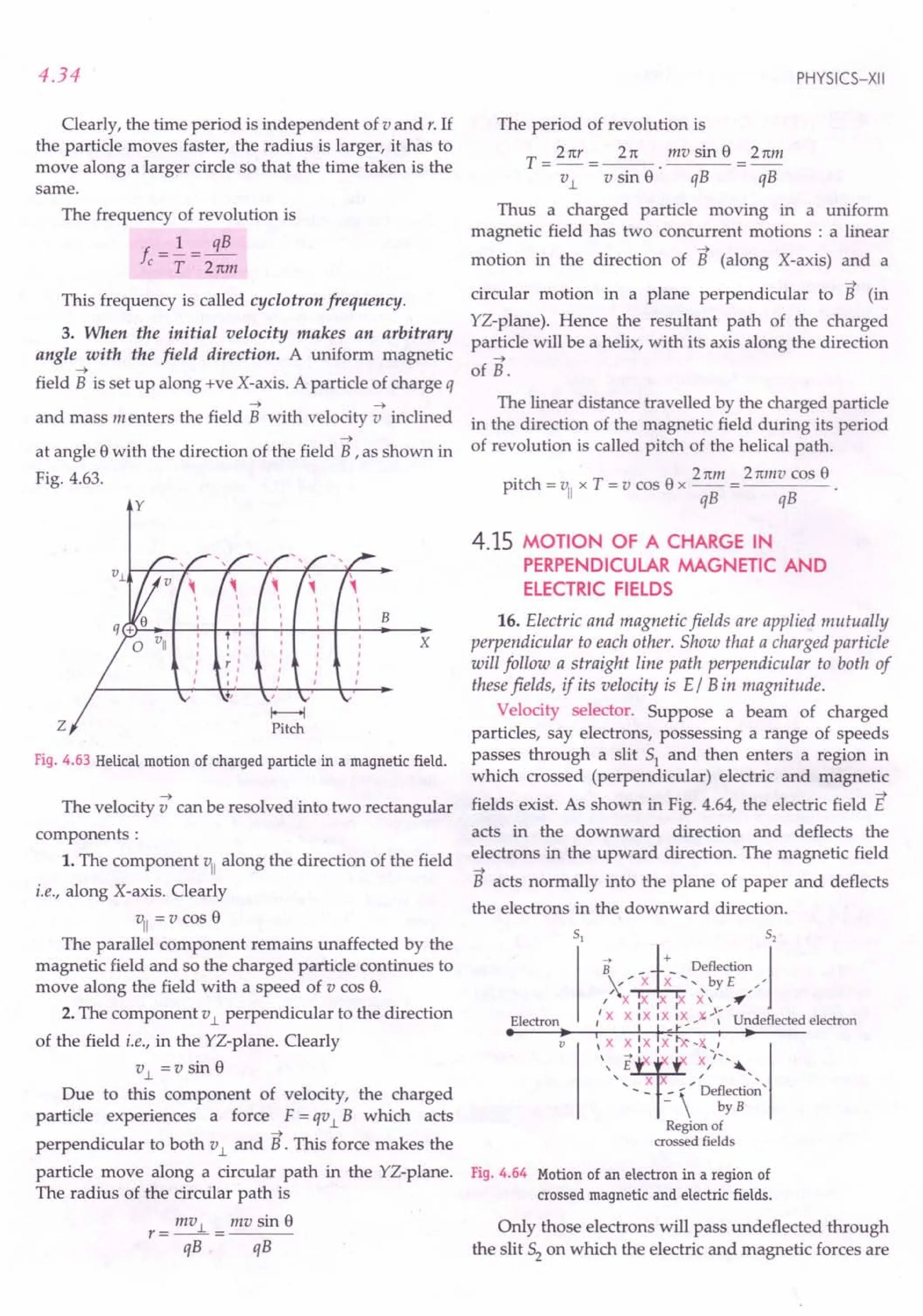
![MAGNETIC EFFECT OF CURRENT
equal and opposite. The velocity v of the undeflected
electrons is given by
E
V=-
B
Such an arrangement can be used to select charged
particles of a particular velocity out of a beam in which
the particles are moving with different speeds. This or
arrangement is called velocity selector or velocity
filter. This method was used by II Thomson to
determine the charge to mass ratio (e / m) of an electron.
eE = evB or
Examples based on
Motion of Charges in Electric
and Magnetic Fields
Formulae Used
1. Electric force on a charge, ~ = qE
2. Magnetic force on a charge, F,n = q v Bsin 8
3. In a perpendicular magnetic field, the charge
follows a circular path.
InV2 mv
q v B = -- or r = -
r qB
T = 2n In and f = 3..!!.-
qB 2nm
--> -->
4. When v makes angle 8with B, the charge follows
helical path.
mv.l mv sin 8 21(r 2nm
r=--= ; T=-=--
qB qB v.l qB
2nmvcos 8
Pitch of helix, h = viiT= v cas 8. T = ----
qB
5. K.E. gained by an electron when accelerated
through a potential difference V,
~mv2=ev :. v=~2:::
Units Used
E is in Vm -1 orNe-I, B in tesla, vinms-I, rin metre.
Example 42. An electron moving horizontally with a
velocity of 4 x 10⁴
m/ s enters a region of uniform magnetic
field of 10-5
T acting vertically downward as shown in
Fig. 4.65(a). Draw its trajectory andfind out the time it takes
to come out of the region of magnetic field. [CBSE F 15]
I
:X X X
I
:X XB X
• I
-e I
'X X X
I
I
:X X X
Fig. 4.65 (a)
4.35
Solution. The electron moves along semicircular
trajectory inside the magnetic field and comes out, as
shown in Fig. 4.65(b). Radius r of the path is given by
mv2
-=qvB
r
mv 9.1 x 10-31 x 4 x 104
r=- = m
qB 1.6 x 10-19 x 10-5
= 9.1x 4 x 10-3m =22.75 x 1O-3m
1.6
I
:X X X
I
e :X XB X
:3X X
e I
:x X X
Fig. 4.65 (b)
Time taken to come out of the region of magnetic
field,
ttr 22 x 22.75 x 10-3
t=-= s
v 7x4x104
= 17.875 x 10⁻⁷ S ::::.1.8x 10-65•
Example 43. An electron travels in a circular path of
radius 20 em in a magnetic field 2 x 10- 3 T. (i) Calculate
the speed of the electron. (ii) What is the potential difference
through which the electron must be accelerated to acquire
this speed?
Solution. Here r =20 em =20 x la-2
m,
B =2 x 10⁻³ T, e = 1.6 x 10⁻¹⁹ C, m =9.1 x 10⁻³¹ kg
(i) Magnetic force on the electron
= Centripetal force on electron
mv2
evB=--
r
eBr
:. Speed, v =-
m
1.6 x 10-19 x 2 x 10-3 x 20 x 10-2
9.1 x 10-31
= 7.0 x 10⁷
ms-t.
(ii) If V is the p.d. required to give speed v to the
electron, then
eV = 1mv2
2
V = mv2
= 9.1 x 10-31 x (7.0 x 107
)2
2e 2x1.6x1O-19
or
= 13.9 x 10³ V ::::.14kV.](https://image.slidesharecdn.com/slaroraclass12thphysicsbyrockytrickster-250318042948-c8b51a5a/75/SL-ARORA-CLASS-12TH-PHYSICS-BY-ROCKY-TRICKSTER-pdf-360-2048.jpg)